User Guide (Future)
Latest Release: Version 24.1
The 3DExperience to NX Bi-directional Translator
The 3DExperience to NX translator may be installed on a number of machines each accessing a central network-floating license.
The 3DExperience to NX Translator is a bi-directional direct database converter between the Dassault Systemes 3DExperience Modelling Application and Siemens NX file format.
It enables the user to convert all forms of 3D Mechanical Design Geometry and Assembly data together with system defined attribute information and colour information, between these two systems. This product is designed for companies using 3DExperience who have selected NX to be their main method of collaboration and communication between OEMs and their customers or suppliers.
The translator can be invoked either interactively or in batch mode.
Primary Product Features
Converts all types of geometry, wireframe, surfaces, trimmed surfaces (faces) and solid models.
Converts assembly structure between both systems.
Converts attribute data including colour and layer information.
Integrated with the 3DExperience installation.
The conversion process can be run interactively or in Batch mode.
Data can be filtered by layer and entity type during processing. Geometry can be filtered and selectively processed.
Uses the 3DExperience API and Siemens NX API to read and write data.
Primary Product Benefits
Being a direct database converter, all pre and post processing is eliminated, saving time.
Reduce costs due to processing time and increase overall conversion success levels by filtering input data and focusing the conversion to only those elements required.
Reduce costs and risks associated to accessing the wrong version of data by integrating the conversion process into a related business process.
With over 20 years industrial use Theorem’s product robustness and quality is well proven, reducing your business risk.
This document will focus specifically on guidance for the use of the translator for the 3DExperience to NX bi-directional product. For information regarding any of Theorem’s product ranges please contact sales@theorem.com
Getting Started
Installation
The installation is run from the .msi file download provided. For full details of the installation process, visit Product Release Notes.
License Configuration
To run any product a valid license file is required. The Flex License Manager is run from the .msi file download provided. This can be accessed from the Product Release Notes. For full details of the installation process, visit Product Release Notes.
Running the Product
Once configured and licensed, the product is ready to be run. There are 3 distinct ways of running the translator:
Interactively from within 3DExperience
The Interactive Interface provides a direct method of importing to and exporting from 3DExperience.
In Batch via CATUtil - DataExchangePLMBatch
The 3DExperience DataExchangePLMBatch Interface provides a direct method of invoking the translator. It can be used on an On Demand basis to translate single or multiple files.
On the Command Line
A command line method of invoking the translator is possible. (3DExperience to NX only)
Translating Interactively from within 3DExperience
Launching 3DExperience with Theorem Plug-ins
The 3DExperience to NX bi-directional translator allows an opened 3DExperience part or assembly to be exported directly to NX, and for an NX part or assembly to be imported directly into the 3DExperience application.
In order to translate from within 3DExperience, the application must be started using a Theorem environment, so that the appropriate Theorem partner plug-ins are available. (See 3DExperience Environment files.)
3DExperience can be started from a desktop shortcut created during installation.
Alternatively, it can be started via the script provided in the Translator installation located in:
<installation_directory>\bin
The script name is:
start_3DEXPERIENCE_Theorem_Multi-CAD_NX<xxxx>_CATIAV6R<version>.cmd
(where <xxxx> should be substituted with the version of NX that you have installed – e.g. 1926, 1953, 1980, 2007, 2206)
(where <version> should be substituted for the version of 3DExperience that you have installed – e.g. 2020x, 2021x, 2022x)
Theorem Interactive Conversion Settings
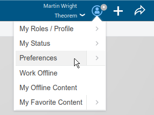
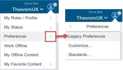
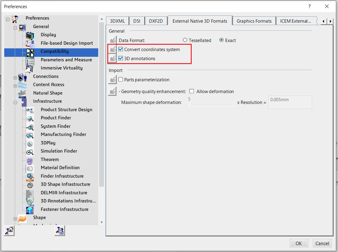
The 3DExperience interface does not currently require the user to apply any specific settings for the translation. There are some general settings that should be checked if required (e.g. for PMI conversion.) These are accessed through Preferences > Legacy Preferences > General > Compatibility > External Native 3D Formats. There are also some options that can be applied within the Theorem setting. These are accessed through Preferences > Legacy Preferences > Infrastructure > Theorem.
|
|
|---|---|
3DExperience 2018x |
3DExperience 2019x onwards |
This page is a standard Dassault Page that sets the preferred mode of conversion (in this case Exact), and also the general options “Convert coordinate systems” and “3D Annotation”. Both of which are toggled on.
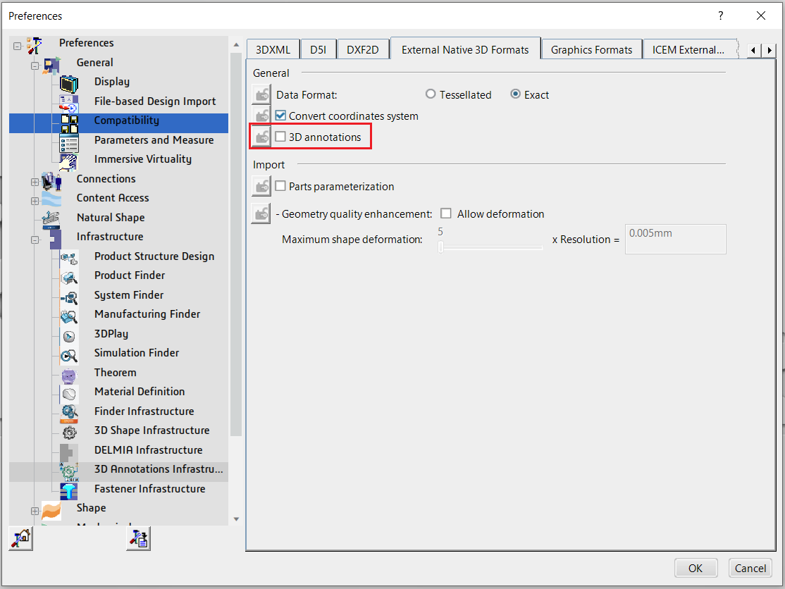
Note – Toggle off 3D Annotations to ensure that the Read PMI option is respected when using the Theorem import, i.e. PMI is displayed on the imported part when it is toggled on and is not displayed when it is toggled off.
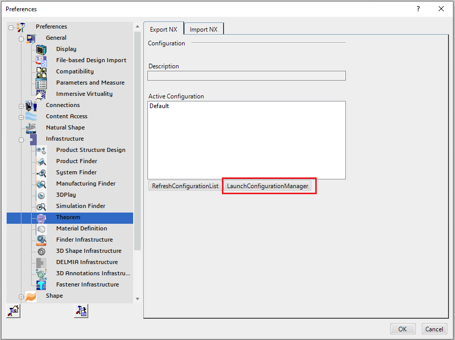
Two dedicated tabs under ‘Infrastructure > Theorem’ allow the user access to Theorem Configurations for import and export. From this Panel, the user can select a predefined configuration or create a new configuration. To create a new configuration, select the ‘LaunchConfigurationManager’ command.
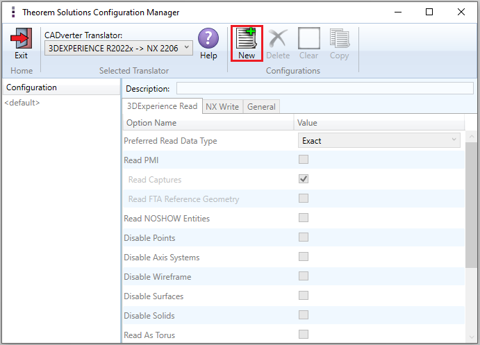
In the configuration manager window, select New. Rename as required.
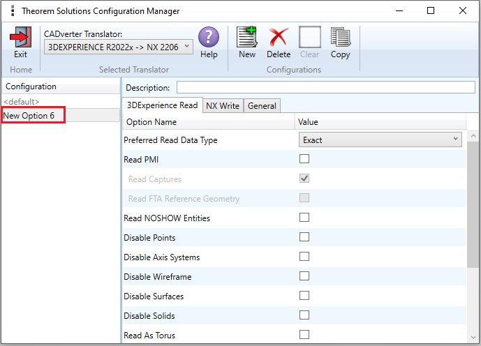
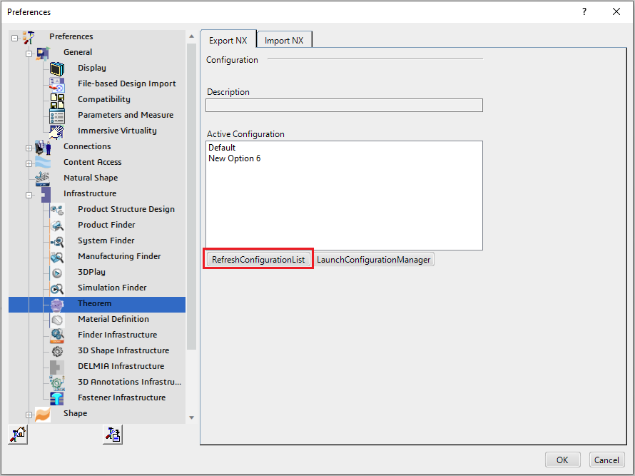
Any new configurations created will be displayed in the Active Configurations list once it has been refreshed. To do this select ‘RefreshConfigurationList’.
Configuration Manager
3DExperience to NX
Within the Configuration Manager, the options that are available to use are grouped into the following 3 areas when translating data from 3DExperience to NX.
3DExperience Read – Those options that affect how data is read from 3DExperience.
NX Write – Those options that affect how data is written to NX.
General – Those options that are common to ALL translation activities regardless of source data. Advanced arguments are added in this tab.
3DExperience Read
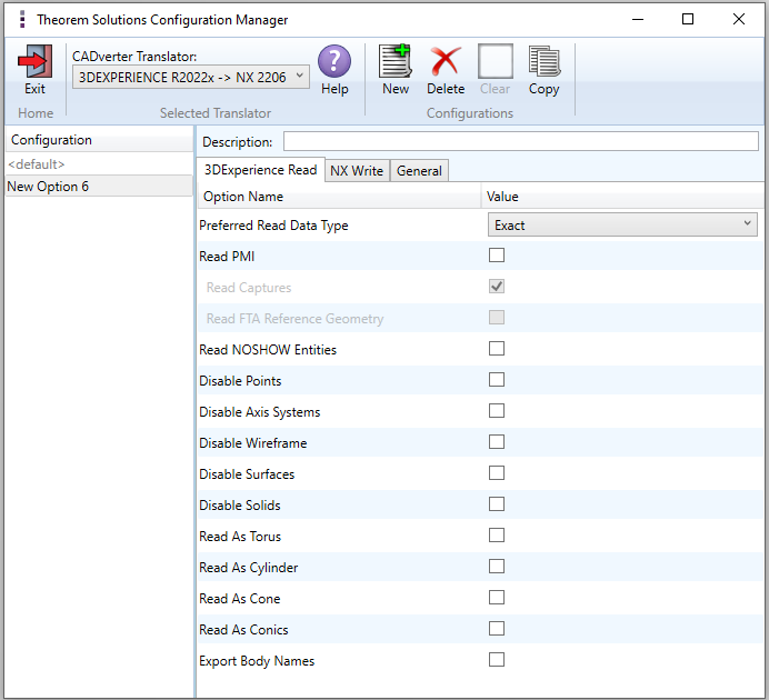
Each of the options displayed in the image above are described below:
Option |
Description |
|---|---|
Preferred Read Data Type |
The setting options are EXACT (default) or TESSELATED. Command Line Syntax:
|
Read PMI |
Enables PMI data read. (Default is OFF.) Command Line Syntax:
Note – When ‘read_pmi’ is enabled it also enables the ‘fill_pmi_arrows’, ‘fill_pmi_text’ and ‘pmi_filled_text’ options. These can be overridden by setting the Advanced arguments ‘dont_fill_pmi_arrows’ and/or ‘dont_fill_pmi_text’. |
Read Captures |
A secondary argument to ‘Read PMI’ and allows control over whether captures are read as part of the process. Default is ON when ‘Read PMI’ is marked as ON. Captures can ONLY be read when ‘Read PMI’ is ON. Command Line Syntax:
|
Read FTA Reference Geometry |
Enables reading of FTA Reference Geometry. (Default is OFF.) FTA Reference Geometry can ONLY be read when ‘Read PMI’ is ON. Command Line Syntax:
|
Read NOSHOW Entities |
Read any entities that are in NOSHOW. Default is to not read NOSHOW entities. Command Line Syntax:
|
Disable Points |
Switches off Point processing. Command Line Syntax:
|
Disable Axis Systems |
Switches off Axis System processing. Command Line Syntax:
|
Disable Wireframe |
Switches off Wireframe processing. Command Line Syntax:
|
Disable Surfaces |
Switches off Surface processing. Command Line Syntax:
|
Disable Solids |
Switches off Solids processing. Command Line Syntax:
|
Read As Torus |
Read Toroidal surfaces in analytical form (default is NURBS.) Command Line Syntax:
|
Read As Cylinder |
Read Cylindrical surfaces in analytical form (default is NURBS.) Command Line Syntax:
|
Read As Cone |
Read Cone surfaces in analytical form (default is NURBS.) Command Line Syntax:
|
Read As Conics |
Read surfaces generated from a Conic in analytical form (default is NURBS.) Command Line Syntax:
|
Export Body Names |
Maintains body names for parts that consist of multiple bodies. Command Line Syntax:
|
NX Write
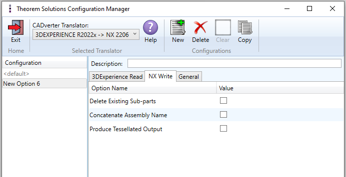
Each of the options displayed in the image above are described below:
Option |
Description |
|---|---|
Delete Existing Sub-parts |
Delete existing assembly subcomponents. (Default is OFF.) Command Line Syntax:
|
Concatenate Assembly Name |
Concatenate top level assy name to all subcomponents. (Default is OFF.) Command Line Syntax:
|
Produce Tessellated Output |
Produce Tessellated NX file. (Default is OFF.) Command Line Syntax:
|
General
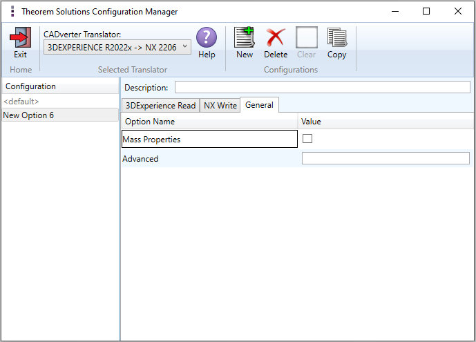
Each of the options displayed in the image above are described below:
Option |
Description |
|---|---|
Mass Properties |
Allows mass property information to be read. Command Line Syntax:
|
Advanced |
Allows any advanced arguments to be added to the configuration manager and applied during the translation. |
NX to 3DExperience
Within the Configuration Manager, the options that are available to use are grouped into the following 3 areas when translating data from NX to 3DExperience. Some options are selectable, some require a file input.
NX Read – Those options that affect how data is read from NX.
3DExperience Write – Those options that affect how data is written to 3DExperience.
General – Those options that are common to ALL translation activities regardless of source data. Advanced arguments are added in this tab.
NX Read
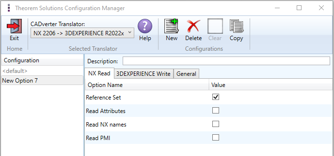
Each of the options displayed in the image above are described below:
Option |
Description |
|---|---|
Reference Set |
Enables reference set processing. (Default is ON.) |
Read Attributes |
Read NX attributes on entity/part/instance. (Default is OFF.) |
Read NX Names |
Read NX entity names (if they exist). (Default is OFF.) |
Read PMI |
Enables PMI data read. (Default is OFF.) |
3DExperience Write
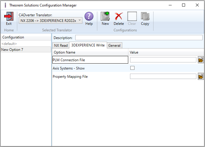
Each of the options displayed in the image above are described below:
Option |
Description |
|---|---|
PLM Connection File |
The PLM Connection file is one of the xml files defining the connection parameters to the PLM database. It is required for creating a connection and logging into a PLM session programmatically. |
Axis System – Show |
Display all axis systems on the imported model. |
Property Mapping File |
A mapping file is used to control which properties are converted from NX to 3DExperience by setting a control value. Setting the control value to 0 will stop a specific property from being exported. Alternatively you can switch the property name that is found in the input data to a different name specified by the user in the output file. This is performed by switching the name between the input name = field 1 and the output name = field 2. The File Line Format is as follows: SourceName, TargetName, Control, Dummy, Dummy, Dummy
Examples:
|
General
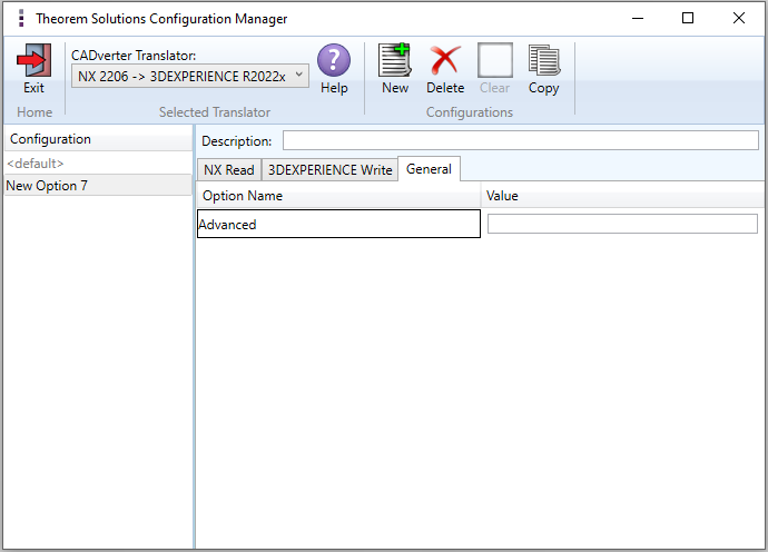
The option displayed in the image above is described below:
Option |
Description |
|---|---|
Advanced |
Allows any advanced arguments to be added to the configuration manager and applied during the translation. |
Interactive Export to NX
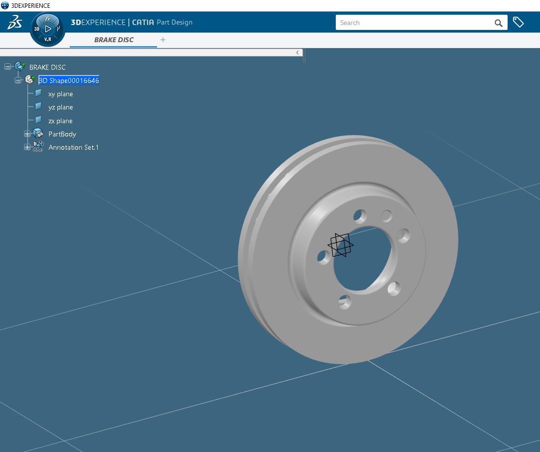
Once the 3DExperience application has been launched, open the product or representation that is going to be exported to NX.
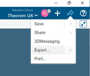
Select the arrow in the top right corner, then from the list displayed select Export.
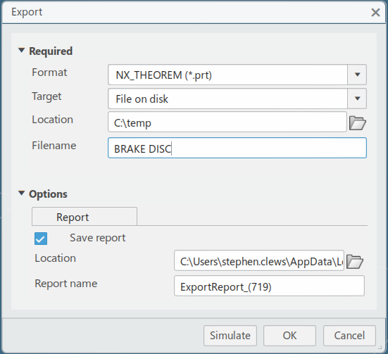
In the Export dialog box displayed, ensure the “Format” is set to NX_THEOREM (*.prt). Select the required location for the file and ensure the Filename displayed is correct. Click OK to initiate the translation.
NX Template Files
If, when a representation is read from 3DExperience, no geometry is found in the representation, all the geometry is hidden or a major write error occurs preventing a NX file being produced, then an empty NX file (named by default as template.prt), will be copied to the expected output file name.
This enables the conversion process to complete successfully and maintains the expected file outputs.
This behaviour is implemented via environment variables set in the Theorem CATEnv file e.g.
%TS_INST%\B422\win_b64\CATEnv\Theorem_Multi-CAD_NX<xxxx>_CATIAV6R<version>.txt
file, typically as follows:
TS_NX_TEMPLATE_FILE=<installation_directory>\data\ug\template.prt
The user can change the content of these NX files, or their location and names as required.
Interactive Import from NX
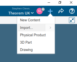
Once the 3DExperience application has been launched it is possible for a model to be imported from NX. To do this select the ‘+’ icon in the top right corner, then from the list displayed select import.
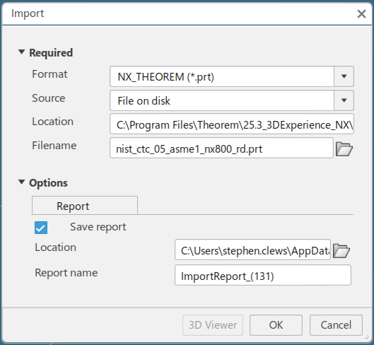
Import dialog box is displayed. Ensure the “Format” is set to NX_THEOREM (*.prt). Click on the folder icon next to the Filename field to choose the required file for import, then click OK to initiate the translation. NX data will be imported into the 3DExperience database and when complete will be opened into a new tab in the user’s session.
3DExperience Multi-CAD
This is an interactive solution that allows users to work with NX parts or assemblies in an active 3DExperience session. This process enables the user to import the NX data and use it for design in context activities. This eliminates the need for a separate translation process.
In order to use the NX data in an active session, firstly the data will need to be imported into 3DExperience. (See Interactive Import from NX.)
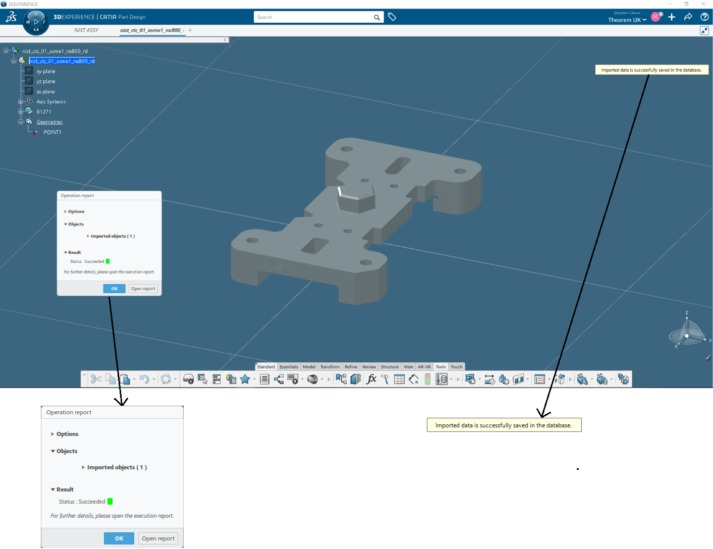
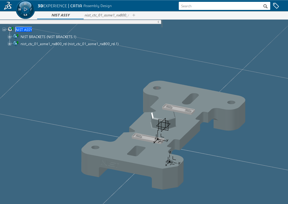
When complete an import successful message will be displayed along with an operation report, with the data opened into a new tab in the user’s session.
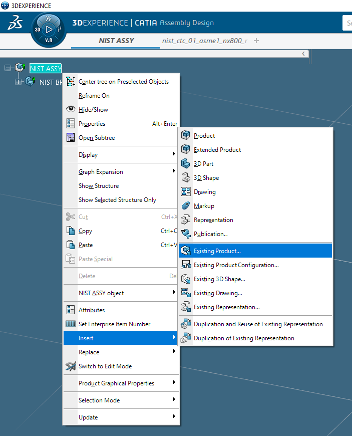
To incorporate the imported data into an existing assembly, select the tab where the assembly is displayed, right click on the required node (typically the top node) and select Insert > Existing Product.
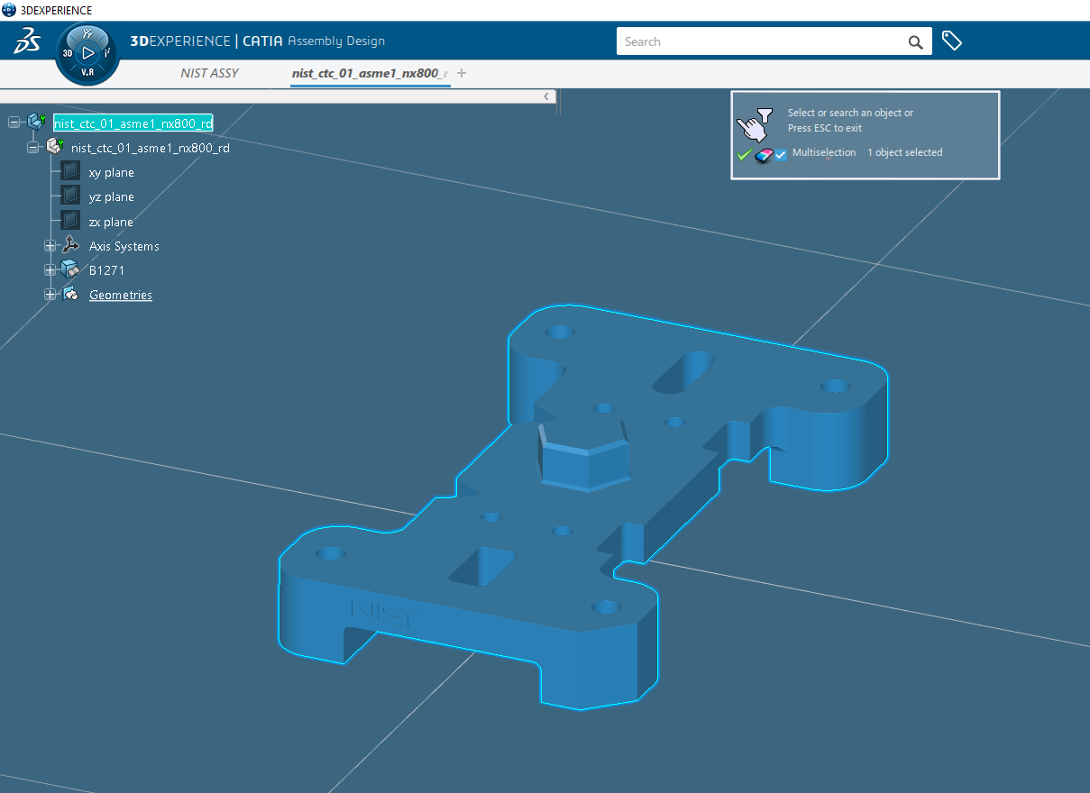
Select the tab where the imported data is displayed, then select the top node to add it to the assembly. If the Multiselection option is toggled on, click on the green tick.
Translating in Batch using CATUtil – DataExchangePLMBatch
Launching DataExchangePLMBatch
The Dassault Systemes CATUTIL Batch Monitor tool can be launched with the correct Theorem enabled environment using the scripts provided in the Translator installation at:
<installation_directory>\bin\start_CATUTIL_Theorem_Multi-CAD_NX<xxxx>_CATIAV6R<revision>.cmd
(where <xxxx> should be substituted with the version of NX that you have installed – e.g. 1926, 1953, 1980, 2007, 2206)
(where <revision> should be substituted for the version of 3DExperience that you have installed – e.g. 2020x, 2021x, 2022x)
It can also be started from the Tools > Utility workbench within an Interactive 3DExperience session.

Batch Export to NX
Here is an example showing what is required in preparation for a 3DExperience database selection and export.
Double click on DataExchangePLMBatch to launch the command.
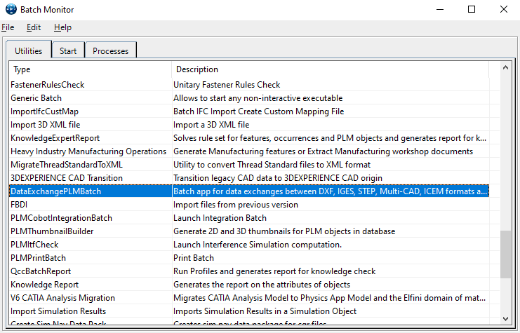
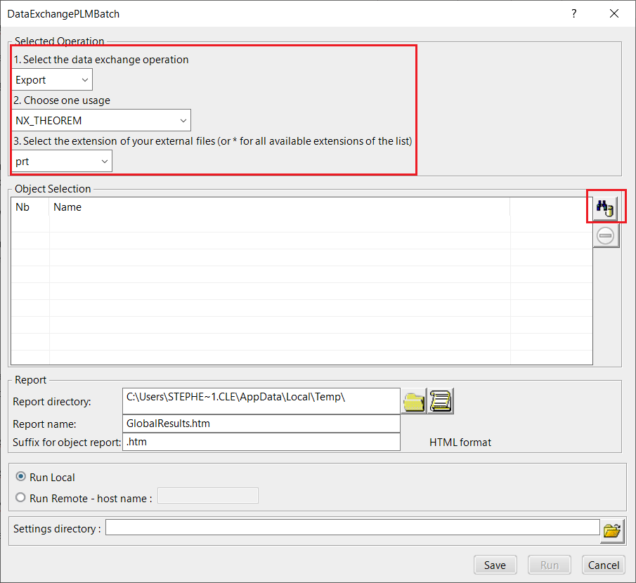
Note selection of “Export” operation, usage “NX_THEOREM” and extension “prt”.
To add the required products to the batch for export, select the 3DEXPERIENCE Platform Object Search icon.
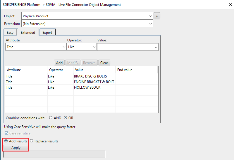
In the subsequent window displayed, add the products using the correct attribute, operator and value ensuring that the correct object type has been selected. (E.g. Physical Product.)
For multiple products ensure that the OR condition has been selected. Select Add results and click Apply to add the list of products to the Object Selection field.

To change the location where both the report and NX files will be saved, select the icon next to the Report directory field, then select the required directory.
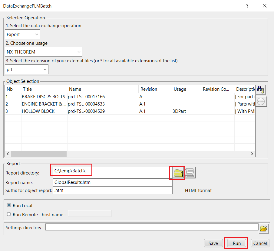
Click Run to initiate the Batch Export to NX.
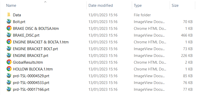
Batch Import from NX
Here is an example showing what is required in preparation for an NX file selection and import.
Double click on DataExchangePLMBatch to launch the command.
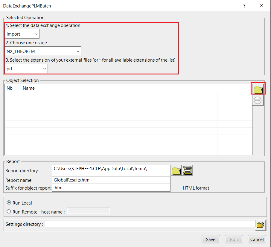
Note selection of “Import” operation, usage “NX_THEOREM” and extension “prt”.
To add the required products to the batch for import, select the 3DVIA – Live File Connector Object Search icon, next to the Object Selection field.
In the subsequent window displayed, add the products by clicking on Member and selecting the required NX files. These will then be added to the Object Selection field.
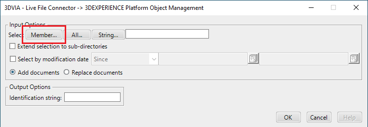
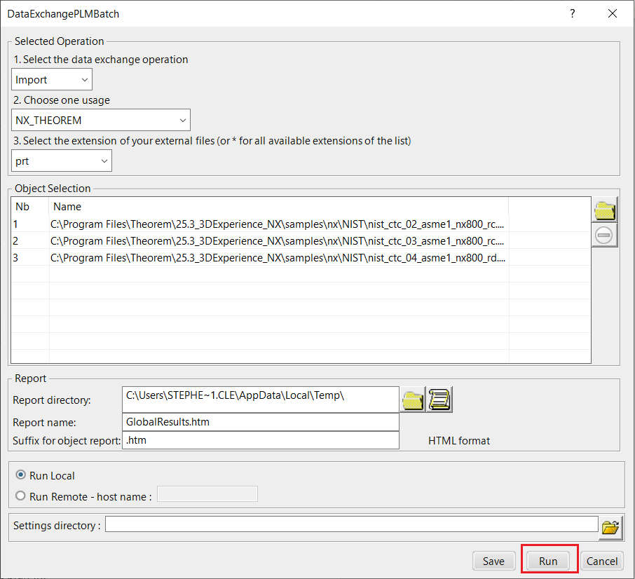
Click Run to initiate the Batch Import from NX.
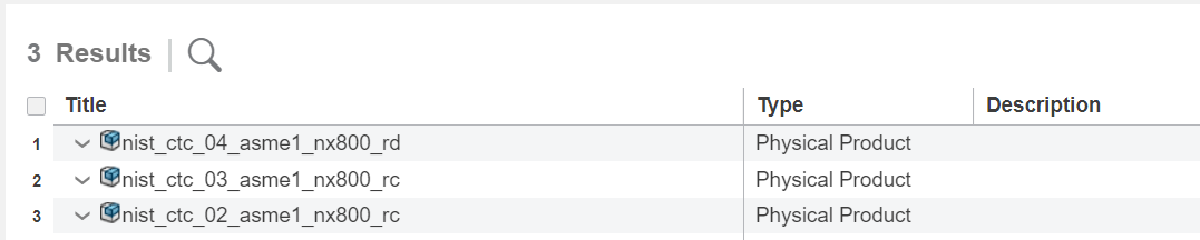
Translating on the Command Line
It is possible to run a 3DExperience to NX translation on the command line, however as all CAD data is saved in the 3DExperience database an XML file will need to be used as the input file instead of a CAD file. This is explained in more detail below. In order to run a translation on the command line the following inputs are required:
<TS_INST>\bin\catia6r<revision>_nx<xxxx>.cmd <input_file> <output_file> <options>
Where:
<TS_INST> is the Theorem Solutions software installation directory.
<revision> is the version of 3DExperience that you have installed – e.g. 2020x, 2021x, 2022x.
<xxxx> is the version of NX that you have installed – e.g. 1926, 1953, 1980, 2007, 2206.
<input_file>
Is an XML file defining access to a specific object in the 3DExperience database.
This file provides user login details (V6R2013x) or a Login Ticket (2015x onwards) (see Creating a Login Ticket), to a specified Enovia repository plus a set of 3 attribute names and values which will uniquely identify the input object required for the conversion.
Examples of the input file XML can be found in the
<TS_INST>\samples\3dexperience folder. These can be modified and saved on your
local drive.
Here is an example of the xml input file for 3DExperience:
<?xml version="1.0" encoding="utf-8"?>
<mc6_read>
  <!-- parameters must be in this ORDER -->
  <!-- parameters only the value passed to V6 -->
  <parameters>
    <attribute name="repository" value="PLM1"/>
    <attribute name="ServerName" value="3dspace.theorem.com"/>
    <attribute name="ServerPort" value="447"/>
    <attribute name="ServerRootURI" value="3dspace"/>
    <attribute name="LoginTicket"
      value="REEyNzM3M0Q1REM2NDgxQzlFNzk1QzIwNjZGRDYzODN8Um9iaW58Um9iaW58fHwwfA=="/>
    <attribute name="PLMType" value="VPMReference"/>
    <attribute name="ReportDirectory" value="C:\TEMP\V6Export"/>
    <attribute name="LicenseData" value="LIC"/>
    <attribute name="BatchXMLFileName" value="Default"/>
  </parameters>
  <!-- arguments both key and value are passed to V6 -->
  <arguments>
    <attribute key="PLM_ExternalID" value="prd-Interfix"/>
    <attribute key="V_version" value="A"/>
    <attribute key="minorrevision" value="1"/>
  </arguments>
</mc6_read>
Note
In some cases, the “minorrevision” value is not required in the XML file, only the V_version value is required. This value could be A.1 for example.
<output_file> is the required output NX file name.
<options> – Options displayed in the configuration manager can be added at the end of the
command using the correct syntax, e.g. read_pmi. (See Configuration Manager –
3DExperience to NX for list of command line syntaxes.)
Progress_file <file name> – The path and file name for the log file e.g. C:\TEMP\progress.log

Log File Generation
Export Process Log Files
In the process of exporting the selected 3DExperience part or assembly, the following log files are generated by the NX Export plug-in.
The process log and error messages are recorded in a .err file located in the
DassaultSystemes CATReport directory. The file is named after the active CATIA component.
e.g.
%CATReport%\model1.err
Additional log files are created in the TSC_TEMP_DIR directory. This directory is defined in
the %TS_INST%\ts_env.bat file.
%TSC_TEMP_DIR%\Read_to_viewer_<input_part_name>.log
Where: <input_part_name> is the name of the input part (or the active part name in interactive usage).
This contains information describing the 3DExperience ‘data read’ processing into Theorem Intermediate data format. Normally a list of entities.
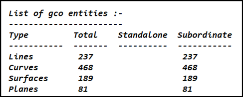
%TSC_TEMP_DIR%\viewer_<part-name>_screen_output.log
Where <part-name> is the selected output file name.
This contains the screen output of the process of writing the data to NX. The status of the translation can be found here.
%TSC_TEMP_DIR%\viewer_<part-name>.log
Where <part-name> is the selected output file name.
This contains detailed process information of the write of the data to NX and contains additional information such as modifiers and options used.
Import Process Log Files
In the process of importing an NX file, the following log files are generated by the NX Import plug-in.
nist_ctc_05_asme1_nx800_rd.err– provides the full processing list of errors, warnings and informationnist_ctc_05_asme1_nx800_rd.log.rpt– provides a short list of the entities created and failednist_ctc_05_asme1_nx800_rd.log.summary– provides start and finish times and the status message code (these can be customised)nist_ctc_05_asme1_nx800_rd.log– provides a single file with data from the other three logs
The process log and error messages are, by default, located in the DassaultSystemes
CATReport directory. The files are named after the selected input file name. e.g. Mypart.prt
would produce the log file names Mypart.err, Mypart.rpt etc.
3DExperience Environment Files
As part of the Theorem installation process, a set of 3DExperience environment files are created which are subsequently used in the launch of 3DExperience and CATUtil sessions to support the Theorem partner plug-ins for NX file imports and exports.
A ‘CATEnv’ file is created for each installed version of 3DExperience.
These environment files are located in the 3DExperience revision specific folder within the Theorem install e.g.
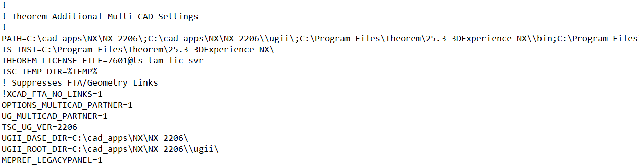
<installation_directory>\B422\win_b64\CATEnv\Theorem_MultiCAD_NX2206_CATIAV6R2020x.txt
<installation_directory>\B423\win_b64\CATEnv\Theorem_MultiCAD_NX2206_CATIAV6R2021x.txt
<installation_directory>\B424\win_b64\CATEnv\Theorem_MultiCAD_NX2206_CATIAV6R2022x.txt
These files consist of the current 3DExperience settings with the required Theorem settings appended at the bottom.
Creating a Login Ticket
Use a browser link (similar to the one below) to your 3DExperience Server:
https://3dspace.2017x.theorem.com:447/3dspace/common/emxNavigator.jsp
A page will appear in the browser.
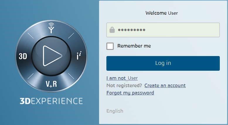
Login as normal, e.g.
User
Password
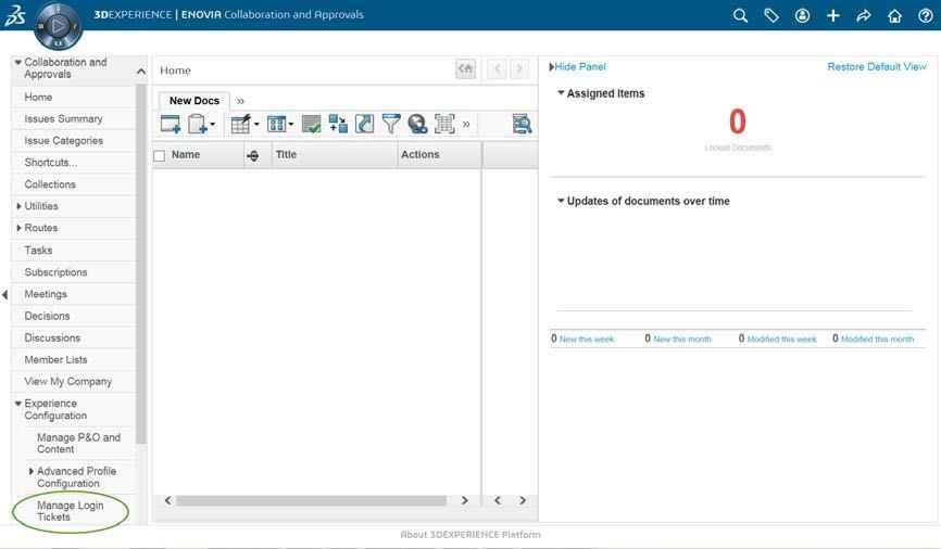
Select Collaboration and Approvals > Experience Configuration > Manage Login Tickets
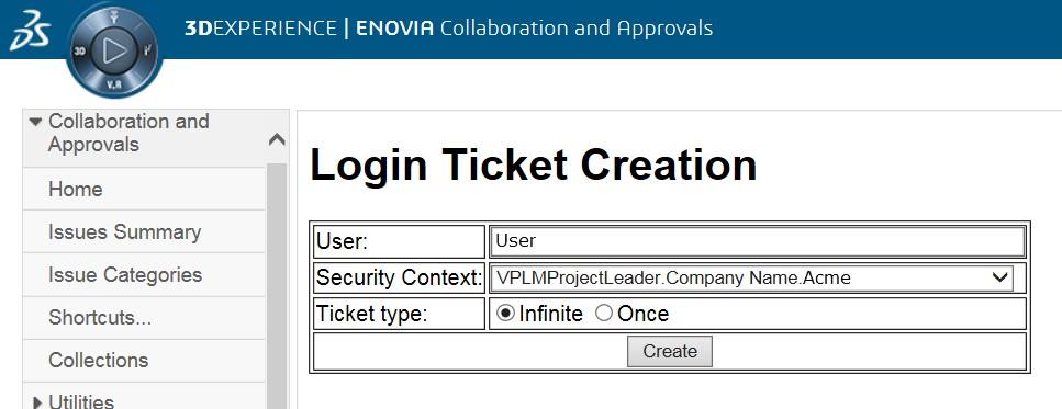
Select the values required for your user:
User and Security Context should already be set, make sure that Ticket Type: Infinite is selected. Then click on ‘Create’.
“Create” will produce the ticket:
REEyNzM3STE1MER2NDgxQzlFNzk1QzIwNjZGNATzDAN8Um9iaW58Um9iaW58fHwwfA==
This can then be used as the ‘LoginTicket’ value explained previously.