User Guide
Using the Product
Default Translations
Default Translation – via the Unified Interface
The Unified Interface can be started via the Start Menu – if a shortcut was added during installation.
Alternatively, the Unified Interface can be run via a Windows Explorer selection in:
<UI_installation_directory>\bin\Unified_Interface.cmd
The following interface will be launched:
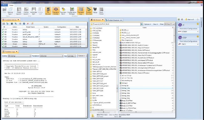
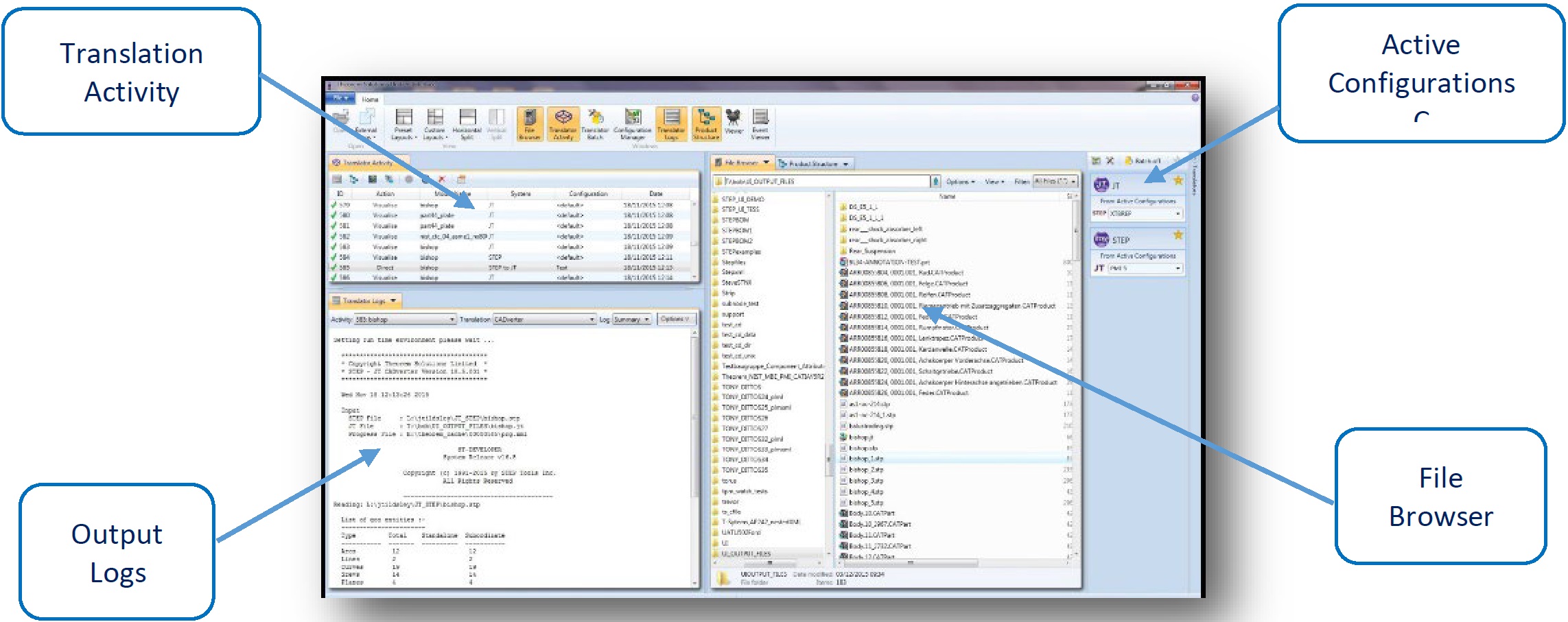
The default layout is split into 4 primary areas that can be altered to the user’s preference:
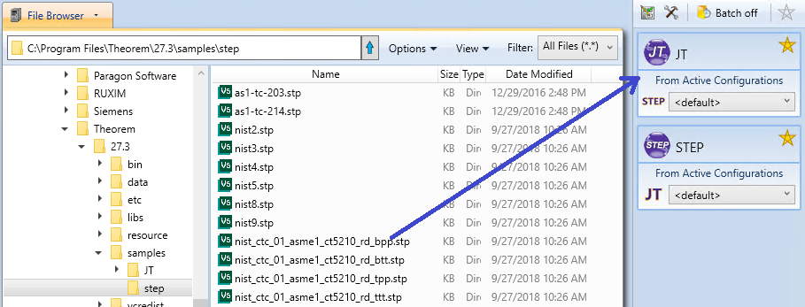
The simplest way to translate from STEP or JT is to drag a file from the file Browser Pane on to the Active Configurations for the translation you require.
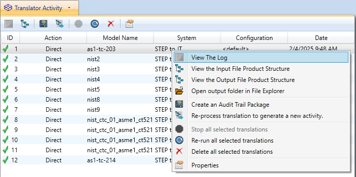
On completion, the Unified Interface will display the activity information and details from the log file created during the translation, if requested, in the Translation Activity and Output Log panes, respectively.
The generated output data can be located by selecting the translation from the Activity pane and opening the output folder:
Default Translation – via the Command Line
STEP-JT
The format of the command is as follows when translating from STEP to JT:
“<Translator_installation_directory>\bin\step_jt.cmd” “path\input_file” “path\output_file”

The example above will translate an STEP sample file provided within the installation and produce the following screen output:
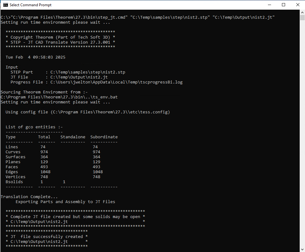
The file will be output to the target location. In this case:
C:\Temp\output\nist2.jt
JT-STEP
The format of the command is as follows when translating from JT to STEP:
“<Translator_installation_directory>\bin\jt_STEP.cmd” “path\input_file” “path\output_file”

The example above will translate a JT sample file provided within the installation and produce the following screen output:
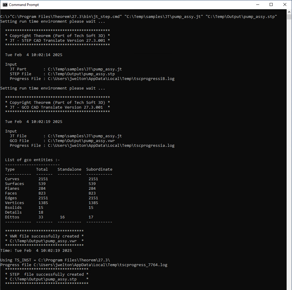
The file will be output to the target location. In this case:
C:\Temp\Output\pump_assy.stp
Translate Customization
Translate allows the information that is read from the source system and written to the target system to be tailored via a set of user specified arguments. Commonly used arguments are supported via the Unified Interface, with Advanced Arguments being described within this document for use in the Unified Interface or via the Command Line invocation.
Common Options for STEP to JT
Within the Configuration Manager panel of the Unified Interface, arguments that can be specified when publishing STEP data into JT are grouped into 3 areas:
STEP Read: Those arguments that affect how data is read from STEP
JT Write: Those arguments that affect how the data is written to JT
General: Those arguments that are common to ALL Publishing activities regardless of source dat
STEP Read Arguments
The image below shows the STEP Read arguments that are available, with their default settings:
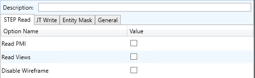
Each of these options is described below:
Option |
Description |
|---|---|
Read PMI |
Enables PMI data read from the STEP file. (Default is OFF). Command Line Syntax:
|
Read Views |
Disables reading of views. (Default is ON). Command Line Syntax:
|
Disable Wireframe |
Disables reading of wireframe entities. (Default is ON). Command Line Syntax:
|
JT Write Arguments
The image below shows the JT Write arguments that are available, with their default settings:

Each of these options is described below:
Option |
Description |
|---|---|
Config File |
Allows a JT configuration file to be specified. Please see Property Mapping Files for a full description of the JT config file format. Command Line Syntax:
|
STEP to JT Entity Mask
The image below shows the Masking arguments that are available, with their default settings:
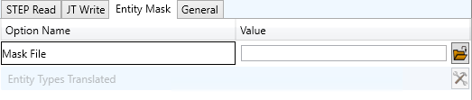
Each of these options is described below:
Option |
Description |
|---|---|
Mask File |
Specifies the Mask File to be written to, that can be referenced by future translations. A Mask file MUST be specified if masking is required. The first line in this file is OFF ALL ENT: Command Line Syntax:
|
Entity Types Translated |
Specifies a list from which to select which entity types are to be processed. These will be added to the Mask file. The following types are available: “POI”,”LIN”,”ARC”,”CON”,”CUR”,”SUR”,”FAC”,”SOL” Command Line Syntax:
|
STEP to JT General
The image below shows the General arguments that are available, with their default settings:
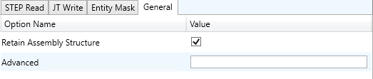
Each of these options is described below:
Option |
Description |
|---|---|
Retain Assembly Structure |
Collapse assembly to a part Command Line Syntax:
|
Advanced |
Provides a text field to enter any command line arguments. |
STEP to JT Advanced Arguments
Theorem’s STEP to JT translator has been configured with default settings that optimise the translation process. However, there are times when a satisfactory result cannot be obtained, so it may be required to deploy one or more Advanced Arguments to improve the translated result.
The following table describes useful Advanced Arguments that can be entered into the General Tab -> Advanced field:
Option |
Description |
|---|---|
Parasolid Tolerant Modelling |
A secondary option to be used when Brep Type = XT Brep (Theorem) output is specified. Enables Parasolid tolerant modelling. Default is ON Command Line Syntax:
|
Factor |
Specify the factor level of Parasolid Tolerant Modelling when turned on. Default is 3. Command Line Syntax:
|
Sew Parasolid Bodies |
A secondary option to be used when Brep Type = XT Brep (Theorem) output is specified. Enables the sewing of Parasolid bodies. Default is ON Command Line Syntax:
|
Tolerance |
Specify the tolerance for the sew command above. Default is 0.01. Command Line Syntax:
|
Incremental Sewing |
Enables incremental sewing when used with Sew Parasolid Bodies. Default is ON. Command Line Syntax:
|
Split Discontinuous Surfaces |
A secondary option to be used when Brep Type = XT Brep (Theorem) output specified. Splits discontinuous surfaces. Default is OFF. Command Line Syntax:
|
Force body creation (No check of Parasolid entities) |
A secondary option enabled when XT Brep (Theorem) output specified. Removes the checking of Parasolid entities. Default is ON. Command Line Syntax:
|
Fix Degenerate Edges |
A secondary option to be used when Brep Type = XT Brep (Theorem) output specified. On face create failure, check and fix any degenerate edges. Default is ON. Command Line Syntax:
|
Specify a Face Edge Tolerance |
A secondary option to be used when Brep Type = XT Brep (Theorem) output specified. Specify an edge tolerance to be used when creating faces. Default is ON. Please see Edge Tolerance below |
Edge Tolerance |
A secondary option used with Specify a Face Edge Tolerance where the tolerance value is assigned. Default is 0.000006. Command Line Syntax:
|
Fix small features in solids |
A secondary option to be used when Brep Type = XT Brep (Theorem) output specified. Remove small edges, sliver and spike faces from solid bodies. Default is OFF. Command Line Syntax:
|
Fix small features in open solids |
A secondary option to be used when Brep Type = XT Brep (Theorem) output specified. Remove small edges, sliver and spike faces from open solids. Default is OFF. Command Line Syntax:
|
Parasolid Trans Delete |
This option causes the CADverter to check for any hidden bodies in the .sldprt file and delete these before exporting the .sldprt file to a parasolid .x_t file. This is because hidden bodies became visible in the export. This option will reduce the processing time for large assemblies. Command Line Syntax:
|
Simplify Geometry |
A secondary option to be used when Brep Type = XT Brep (Theorem) output specified. Simplify Geometry. Default is OFF. Command Line Syntax:
|
Common Options for JT to STEP
Within the Configuration Manager pane of the Unified Interface, arguments that can be specified when publishing JT data into STEP are grouped into 3 areas:
JT Read – Those arguments that affect how data is read from JT
STEP Read – Those arguments that affect how data is written Into STEP
General – Those arguments that are common to ALL Publishing activities regardless of source data
JT Read Arguments
The image below shows the JT Read arguments that are available, with their default settings:
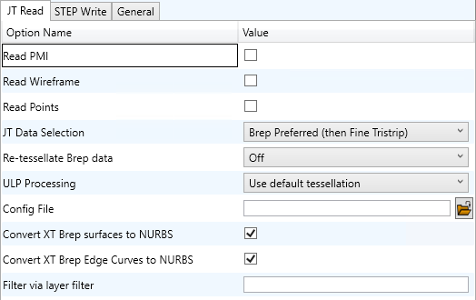
Each of these options is described below:
Option |
Description |
|---|---|
Read PMI |
Read JT wireframe data. Default is OFF. Command Line Syntax:
|
Read Wireframe |
Read JT point data. Default is OFF. Command Line Syntax:
|
Read Points |
Enables reading of Points |
JT Data Selection |
Select Brep or tessellated data read. Default is ‘Brep Preferred (then fine facet)’. Command Line Syntax:
|
Re-tessellate Brep data |
|
ULP Processing |
How to process ULP data in the JT part. Default is ‘Use Default Tessellation’. Command Line Syntax:
|
Config File |
Config File for Brep or ULP tessellation. Command Line Syntax:
|
Retain Assembly Structure |
Enables Assembly Structure to be removed. Selecting this option will remove all assembly structure and collapse ALL geometry into a single selectable object |
Convert XT Brep surfaces to NURBS |
Read XT Brep surfaces as NURBS surfaces (else read in native form). Default is ON. Command Line Syntax:
|
Convert XT Brep Edge Curves to NURBS |
Read XT Brep edge curves as NURBS curves (else read in native form. Default is ON. Command Line Syntax:
|
Filter via layer filter |
Supply layer filter(s) separated by commas and double quoted. Default is OFF. Command Line Syntax:
|
STEP Write Arguments
The image below shows the STEP Write arguments that are available, with their default settings:
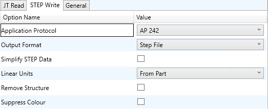
Each of these options is described below:
Option |
Description |
|---|---|
Application Protocol |
Define which STEP protocol to use, Default is AP 242 Command Line Syntax:
|
Output Format |
Read JT point data. Default is OFF. Command Line Syntax:
|
Simplify STEP Data |
Enables writing of analytic geometry where possible. Command Line Syntax:
|
Linear Units |
Set the Linear Units to be used in the STEP file, Default is to use the units from the input file: Command Line Syntax:
|
Remove Structure |
Collapse assembly to a part Command Line Syntax:
|
Suppress Colour |
Disable colour processing Command Line Syntax:
|
JT Configuration File
Introduction
A configuration file contains the settings for your translations. The configuration file can be specified using the command line option –config or -z.
If this is not supplied the following config file will be used:-
tessSTEP.config in %TS_INST%\etc directory (where TS_INST = Installed directory)
The JT configuration file contains various sections, each containing different settings based on the section.
The Setup Section
The setup options in the configuration file define how your files are translated. The setup section is the first part of the configuration file and contains a series of standard translator options.
To edit setup options
Open an existing configuration file with a text editor.
Edit the configuration file options listed in the table below.
Save the configuration with a .config extension
Option name |
Keywords |
Example |
|---|---|---|
EAITranslator |
EAITranslator { |
EAITranslator { |
OutputDirectory |
“path to directory” |
OutputDirectory = “/home/<user>/” |
CommonPartsPath |
“path to directory” |
CommonPartsPath= “/myaccount/jtparts/” |
chordalOption |
“RELATIVE” “ABSOLUTE” |
chordalOption = “RELATIVE” |
structureOption |
“PER_PART” “MONOLITHIC” “FULL_SHATTER” |
structureOption = “MONOLITHIC” |
WriteWhichFiles |
“ALL” “ASSEMBLY_ONLY” “PARTS_ONLY” |
WriteWhichFiles = “ALL” |
compression |
true / TRUE / false / FALSE |
compression = true |
triStripOpt |
true / TRUE / false / FALSE |
triStripOpt = false |
seamSewing |
true / TRUE / false / FALSE |
seamSewing = true |
seamSewingTol |
any integer |
seamSewingTol = 0.001 |
includeBrep |
true / TRUE / false / FALSE |
includeBrep = false |
brepPrecision |
“SINGLE” “DOUBLE” |
brepPrecision = “SINGLE” |
autoNameSanitize |
true / TRUE / false / FALSE |
autoNameSanitize = true |
updateChangedPartsOnly |
true / TRUE / false / FALSE |
updateChangedPartsOnly = false |
verboseReporting |
true / TRUE / false / FALSE |
verboseReporting = false |
writeAsciiAssembly |
true / TRUE / false / FALSE |
writeAsciiAssembly = false |
singlePartsNoAssem |
true / TRUE / false / FALSE |
singlePartsNoAssem = false |
smartLODgeneration |
true / TRUE / false / FALSE |
smartLODgeneration = true |
autoLowLODgeneration |
true / TRUE / false / FALSE |
autoLowLODgeneration = true |
numLODs |
any integer |
numLODs = 3 |
JtFileFormat |
95, 100, 105, 106, 110, 111 |
JtFileFormat = “95” |
includeULP |
PASSTHROUGH / TRUE / FALSE |
includeULP = “PASSTHROUGH” |
ulpPrecision |
Real Value |
ulpPrecision = 0.001 |
close brace |
} |
} |
The Level of Detail Section
The level of detail section of the configuration file contains the tessellation and simplification information for each level of detail in the file.
This section consists of several sets of level of detail (LOD) information, and the number of these sets depends on the number you specified on the numLODs line in the configuration file.
To edit level of detail options
Open an existing configuration file in a text editor.
Edit the configuration file options listed below.
Save the configuration with a .config extension
Option name |
Keywords |
Example |
|---|---|---|
LOD |
LOD “lod number” { |
LOD “1” { |
Level |
any integer |
Level = 1 |
Chordal |
any number |
Chordal = 0.001 |
Angular |
any number |
Angular = 25 |
Length |
any number |
Length = 1 |
Label |
any string |
“ud_FINE” |
FeatureSuppression |
any integer |
FeatureSuppression = 0 |
Simplify |
any number |
Simplify = 0.60 |
AdvCompressionLevel |
any number |
AdvCompressionLevel = 0.0 |
ULP |
true / false |
|
close brace |
} |
} |
The Filter Section
The filter section of the configuration file contains the filename and metadata filtering information. Edit this section if you want to change how the translator sanitizes filenames and filters metadata keys.
To edit filter options
Open an existing configuration file with a text editor.
Edit the configuration file options from the table below.
Save the configuration with a .config extension
Option name |
Keywords |
Example |
|---|---|---|
Filter |
Filter { |
Filter { |
FilenameSanitizeSet |
“string of characters” |
FilenameSanitizeSet = “abc123.” |
FilenameSanitizeSetAdd |
“string of characters” |
FilenameSanitizeSetAdd = “4l” |
FilenameSanitizeSetDelete |
“string of characters” |
FilenameSanitizeSetDelete = “c” |
MetadataKey |
“string of characters” |
MetadataKey = “metadata key to exclude” |
close brace |
} |
} |
The Metadata section
The metadata section sets which metadata to attach to all parts, assemblies and nodes of the model.
Note: Be sure to add these options to the configuration file in pairs: one line to define the metadata key and one line to define the metadata value.
To edit metadata options
Open an existing configuration file (.CONFIG) in a text editor.
Edit the configuration file options shown in the table below.
Save the configuration with a .config extension
Option name |
Keywords |
Example |
|---|---|---|
Metadata |
Metadata { |
Metadata { |
AddToParts |
“string of characters” |
AddToParts = “<metadata key>” AddToParts = “<metadata value>” |
AddToAssemblies |
“string of characters” |
AddToAssemblies = “<metadata key>” AddToAssemblies = “<metadata value>” |
AddToAllNodes |
“string of characters” |
AddToAllNodes = “<metadata key>” AddToAllNodes = “<metadata value>” |
close brace |
} |
} |
The Special Section
The special section of the configuration file contains lines that are unique to this translator.
To edit special options
Open an existing configuration file with a text editor.
Edit the configuration file options shown in the table below.
Save the configuration with a .config file extension.
Option |
Keyword |
Example |
Default Value |
|---|---|---|---|
STEPOptions |
STEPOptions { |
STEPOptions { |
|
ProjectFile |
Full system file path |
ProjectFile = “P:\apps\STEP2009\Samples.ipj” |
“” |
IgnoreMigration |
true/TRUE false/FALSE |
IgnoreMigration = true |
false |
ReportFilename |
Full system file path |
ReportFilename = P:\caddata\translation\result\part55 |
C:%TEMP%\tscprogressyi |
OutputUnits |
mm / millimetres / cm / centimetres / m / metre / metres / inches / feet / yards / inputUnits |
OutputUnits = mm |
inputUnits |
StructureOutputType |
JT / PLMXML / PLMXMLJT |
StructureOutputType = JT |
JT |
PLMXMLPropertyMappingFile |
File Name |
PLMXMLPropertyMappingFile = “mapping_file.txt” |
“” |
brepType |
XT / JT / XTJT |
brepType = XT |
JT |
ParasolidTolerantModelling |
true/TRUE false/FALSE |
ParasolidTolerantModelling = true |
true |
ParasolidTolerantModellingFactor |
Any positive integer |
ParasolidTolerantModellingFactor = 3 |
3 |
SewParasolidBodies |
true/TRUE false/FALSE |
SewParasolidBodies = true |
true |
SewParasolidBodiesTol |
Any number |
SewParasolidBodiesTol = 0.01 |
0.01 |
IncrementalSewing |
true/TRUE false/FALSE |
IncrementalSewing = true |
true |
IncrementalSewingNoOfIterations |
true/TRUE false/FALSE |
IncrementalSewingNoOfIterations = 5 |
5 |
ExplodeSolidstoFaces |
true/TRUE false/FALSE |
ExplodeSolidstoFaces = false |
false |
SplitDiscontinuousSurfaces |
true/TRUE false/FALSE |
SplitDiscontinuousSurfaces = true |
false |
ForceBodyCreation |
true/TRUE false/FALSE |
ForceBodyCreation = true |
true |
FixDegenerateEdges |
true/TRUE false/FALSE |
FixDegenerateEdges = true |
true |
FaceEdgeTol |
Any number |
FaceEdgeTol = 0.000006 |
0.000006 |
FixSmallFeaturesSolids |
true/TRUE false/FALSE |
FixSmallFeaturesSolids = false |
false |
FixSmallFeaturesOpenSolids |
true/TRUE false/FALSE |
FixSmallFeaturesOpenSolids = false |
false |
SimplifyGeometry |
true/TRUE false/FALSE |
SimplifyGeometry = false |
false |
BrepWireframe |
true/TRUE false/FALSE |
BrepWireframe = true |
true |
ProduceTessellatedOutput |
true/TRUE false/FALSE |
ProduceTessellatedOutput = false |
false |
ExpandPart |
true/TRUE false/FALSE |
ExpandPart = false |
false |
ReuseSolids |
true/TRUE false/FALSE |
ReuseSolids = false |
false |
CADPropertyMappingFile |
File Name |
CADPropertyMappingFile = “mapping_file.txt” |
“” |
SavedViewsViewSetName |
“string of characters” |
SavedViewsViewSetName |
“SavedViews” |
AnnotationPlanesViewSetName |
“string of characters” |
AnnotationPlanesViewSetName |
“AnnotationPlanes” |
Close brace |
} |
} |
Property Mapping Files
Property mapping files are required for CAD property Mapping and PLMXML Property Mapping
A Property Mapping File is a comma separated text file containing information of how CAD properties from the source system will be mapped into the target file.
The format is as follows:
Lines beginning with a “#” are treated as comment lines and are ignored.
Any space characters will be treated as part of the item
Lines containing a mapping must contain 6 items separated by 5 commas
Item |
Description |
|---|---|
Source name |
The attribute name in the Source System |
Target name |
The attribute name in the Target File |
Data derived from |
0 - Do not convert 1 - Use the source value as given 6 - Use the source value as given and hide the property Note! Value 6 For CAD Mapping Files ONLY (Not PLMXML) |
Default Value |
Not currently used |
Value Type |
Not currently used |
Default Units |
Not currently used |
An Example of a mapping file is shown below:
# Mapping from input attribute name to Target property name
#
# Line Format:-
# Source name,Target name,Data derived from,Default Value,Value Type,Default Units
#   Data derived from:-
#   0 - Do not convert
#   1 - Use the source values as given
#   6 - Use the source value as given and hide the property
#
_ActivateBOM,NULL,0,0,,
_LastModifier,NULL,0,0,,
_Maturity,NULL,0,0,,
_PrdVersion,NULL,0,0,,
_ReferenceTimeStamp,NULL,0,0,,
_Responsible,NULL,0,0,,
COG M,ud_CAD_CENTER_OF_GRAVITY,1,0,,
COMPONENTS PRINCIPAL AXES ,NULL,0,0,,
DENSITY Kg/M^3,NULL,0,0,,
INERTIA MATRIX KgM2,ud_CAD_MOMENT_OF_INERTIA,1,0,,
INERTIA VOLUME M^3,ud_CAD_VOLUME,1,0,,
INERTIA WET AREA M^2,ud_CAD_SURFACE_AREA,1,0,,
MASS Kg,ud_CAD_MASS,1,0,,
PRINCIPAL MOMENTS KgM^2,NULL,0,0,,
FILESAVETIME,File Last Modified,1,0,,
LOCALE,LOCALE,1,0,,
Masterdata Version,Masterdata Version,1,0,,
Material Details,Material Details,1,0,,
PART_NUMBER,PART_NUMBER,1,0,,
MPARTNAME,Source Model Name,1,0,,
Source,SourceName,1,0,,