User Guide
Using the JT to SW Composer Converter
Once the software is installed and licensed, the product will be ready to be used. There are three separate methods available for running the JT to SWX Composer converter;
Interactive, from within the SWX Composer application using the File Open interface. This method is supported using either a Theorem JT to SWX Composer Interactive, Sync or Enterprise Sync license
Batch processing - using the SWX Composer Sync interface. This method is supported using either a Theorem JT to SWX Composer Sync or Enterprise Sync license.
Command line processing - using either the direct Composer converter executable, or the JT Composer Enterprise Sync or Large Assembly Processing batch scripts with a Windows command shell. All these methods of running the converter from the command line are supported when using a Theorem JT to SWX Composer Enterprise Sync license.
Interactive Use of JT to SW Composer
The JT to SWX Composer converter is automatically invoked when a JT file is selected from the SWX Composer File Open menu.
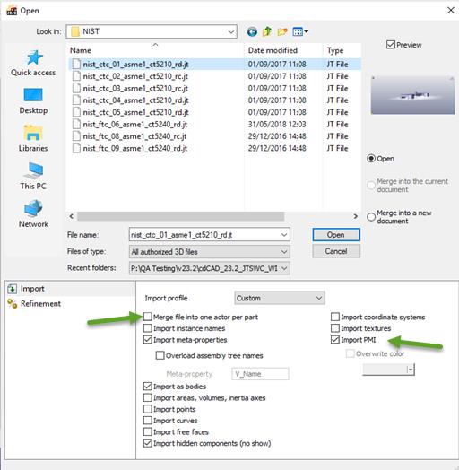
During the processing a dialog is displayed showing the progress of the translation process. If any problems occur during the processing the information will be displayed in this dialog window.
Once the translation is complete the JT data is displayed in the SWX Composer graphics window. Any assembly structure is shown in the Composer Assembly window and all associated JT properties are available in the Composer Property area.
Having imported the JT data, it can now be fully utilized within the SWX Composer application.
NOTE: If PMI data is present in the JT file then in certain cases this may not be read. Ensure that the ‘Merge file into one actor per part’ is unchecked. (see diagram above)
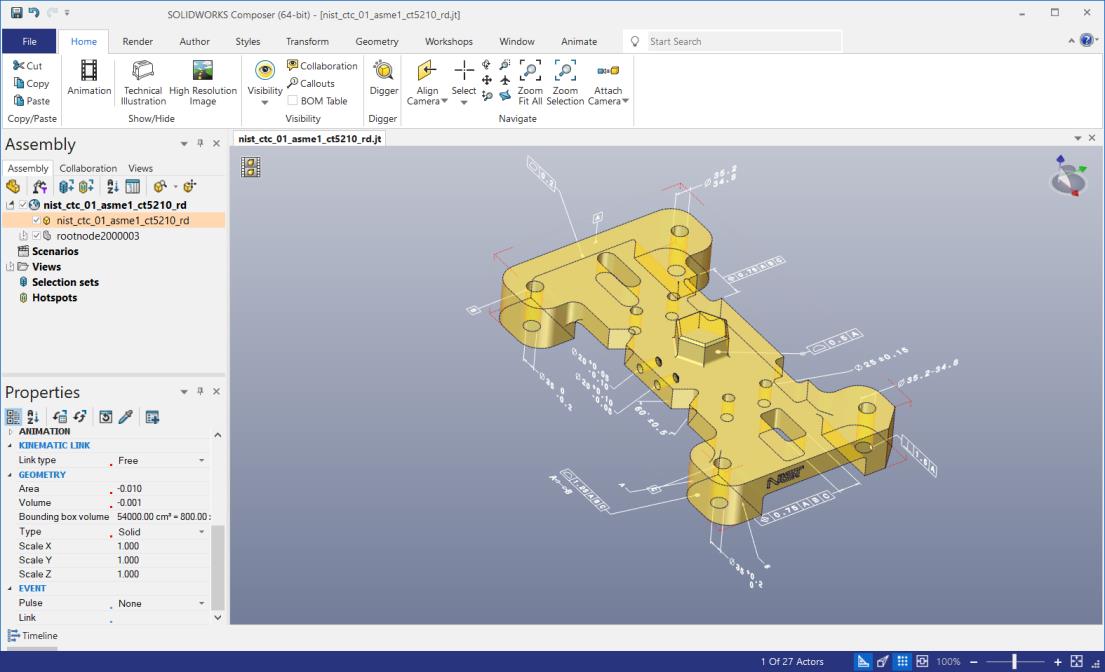
The diagram above shows an example of a JT file imported into the SWX Composer application showing the graphics in the main display area as well as the assembly structure and properties imported during the process.
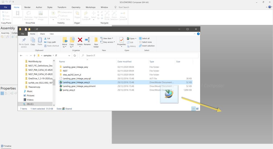
Alternatively, a JT file can be imported interactively, by simply dragging and dropping the file from a folder.
Using the SW Composer Sync interface
To launch the SW Composer Sync interface you can select and run the shortcut on the desktop or in the SolidWorks install folder. Using the SW Composer Sync interface enables multiple JT files to be processed in batch. Having started the SW Composer Sync Interface you can select single or multiple files to be processed.
Using the Filter selector for JT / PLMXML data you can restrict the files shown in the file selector dialog. Having selected the files press the “Add to List” button to add the files to the list of items to be processed.
Once all the input files have been selected simply press the “Translate” button to start processing the files sequentially.
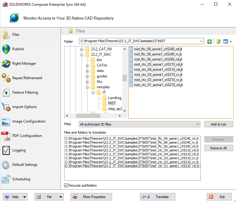
Use the other features of the Composer Sync Interface e.g. Publish, to control the style of output to be generated.
Using the SW Composer Enterprise Sync interface
The SWX Composer Enterprise Sync interface allows the converter to be invoked from a command line prompt. Consequently, it is possible to integrate the translation of JT data to SWX Composer output as part of any workflow, including the integration of the converter into any PDM/PLM process.
There are three methods provided for running the converter using the Enterprise Sync command line mode. These are;
%TS_INST%\bin\ComposerConverter.exe - standard translation command line executable for processing JT or PLMXML files directly as a single event.
%TS_INST%\bin\SWX_Composer_lap.cmd - batch script process which separates the processing of the JT assembly data from the processing of the subordinate part geometry files. This method will automatically generate the SWX Composer output in a shattered file format consisting of a “.smgXml” top level SWX Composer assembly file with subordinate “.smgXml/.smgGeom” files for the subordinate component part files.
%TS_INST%\bin\jt_composer.cmd - batch script process which supports the processing of JT files outputting the results into a nominated folder. The format of the output can be further controlled by the addition of a JT options file with parameter settings to influence the processing.
Using the ComposerConverter.exe Mechanism
To invoke the converter using the ComposerConverter.exe simply input the name of the executable from a command prompt window followed by the name of the JT file to be processed.
e.g. %TS_INST%\bin\ComposerConverter.exe %TS_INST%\samples\pump_assy.jt

When the processing is completed the resultant “.smg” file e.g. nist_ctc_01_asme1_ct5210_rd.smg will be created in the same folder as the original input JT file.
Using the SWX Composer Sync Interface you can specify Composer output processing requirements which can be saved to an external “.seeb” file. The previously saved “.seeb” file can be given as an optional argument to the ComposerConverter.exe to set any of the processing requirements
e.g. …\bin\ComposerConverter.exe …\pump_assy.jt …\usersettings.seeb
The SWX Composer output would then be created in line with the specific converter options defined in the input “.seeb” file.
Processing Large Assemblies with the SWX_Composer_lap.cmd
The SWX_Composer_lap.cmd is specifically designed for processing large assemblies that are created in either native JT using either PER_PART or FULL_SHATTER data or PLMXML files with subordinate JT part files. In doing so the batch script will process the assembly structure separately from processing the subordinate part files and force the creation of shattered SWX Composer output. Therefore the output will consist of a top level “.smgXml” format file for the overall assembly structure. The subordinate part files will be recreated using “.smgXML/.smgGeom” format output. Opening the top level assembly “.smgXml” file within SWX Composer will open all of the subordinate data automatically.
e.g. %TS_INST%\bin\SWX_Composer_lap.cmd %TS_INST%\samples\landing_gear.jt
The resultant output “.smgXml” & “.smgGeom” files will automatically be written to the same folder that the input data was in. Alternatively, an additional optional argument can be entered which will nominate the folder name to be used when creating the output.
e.g. …\bin\SWX_Composer_lap.cmd …\landing_gear.jt C:\output_folder
Using this method, the output data will be written to the nominated folder.
Using the jt_composer.cmd Script
The jt_composer.cmd script provided in the %TS_INST%\bin folder is designed for automating the processing of JT input data. It also allows the user to control the location of the output creation folder, including the location of process log files. In addition, the user can optionally specify a JT process configuration options file to be used for the conversion.
e.g. %TS_INST%\bin\jt_composer.cmd C:\input\any.jt C:\output_folder <JT_opt_file>

The jt_composer.cmd script manages the output creation by using the following process;
It validates that the JT input data is available for processing. If it cannot locate the JT input data an error message is reported, and the process terminates.
It verifies that the output folder specified exists. If it doesn’t already exist, the process will attempt to create the specified output folder. If it’s unable to do so then then an error message is reported, and the process terminates.
It sets the value of TS_TEMP_DIR to the location of the output folder. This ensures that both the Composer output and processing log files are held in the same location.
It sets the variable TS_MCAD_READ_OPTIONS_FILE to reference either the name of the options file given as the third command line argument. Alternatively, it sets the variable to point to the default JT options file %TS_INST%\data\jt\jt_3dvia_opts.txt
The nominated options file identified in step #5 is parsed for two specific options being set, read_pmi and output_fullshatter. These settings are used to determine the processing requirements of PMI processing as well as SMG output settings. The output_fullshatter option triggers the SMG output to be created using the smgGeom/smgXml representation. These settings are then reflected in a temporary Composer SEEB file that is automatically authored.
The automatic SEEB file is created using the naming convention of ts_seeb_<jt_filename>.seeb
The standard ComposerConvertor.exe is finally executed with the name of the JT file and the derived SEEB file being used as arguments to the process.
The process terminates with an appropriate error status being set.
Note, to monitor the jt_composer.cmd script processing set the environment variable TSC_ECHO=on in the command shell prior to running the process. Echo of the lines of the batch script will be echoed to the screen to analyse the processing in detail. In addition, the temporary SEEB file, which is normally deleted at the end of the processing, will be retained in the output folder for further investigation.
Processing JT Assembly Structure Only
When processing JT assemblies there are situations where you may only want to process the assembly structure and not the subordinate geometry. For example, if you are processing a PLMXML assembly structure which references subordinate CATPart component files, rather than conventional JT components, then you could process only the PLMXML assembly structure in isolation of processing the CATPart files using the standard Composer interface.
To process the assembly structure only use the jt_composer.cmd script and reference a JT options file that contains the struct_read option setting. The struct_read option will limit the translator to only processing the assembly structure. Consequently, all subordinate geometry files will be ignored during the translation process. See the section titled “Configuring JT to SW Composer Options” for detailed information on using alternate options files.
Configuring JT to SW Composer Options
There are several Theorem optional settings available to configure the conversion functionality when running the JT to SWX Composer. These options are defined in the default JT options file located in software installation folder in the file named %TS_INST%\data\jt\jt_3dvia_opts.txt
The options available are documented within the file itself. The format of the document is such that any line that begins with an asterisk, *, character will be treated as a comment. All other lines will be treated as active option settings.
JT Options File Settings
The following table describes the option value and the changes that result from using the option during conversion.
Option Setting |
Description |
|---|---|
* |
Any line that begins with an asterisk character is treated as a comment and therefore ignored during processing |
struct_read |
This option will force the JT read process to any read the JT assembly structure information. Therefore, any geometry files referenced by the JT assembly will be ignored during the processing. The resultant Composer output would maintain the references to the subordinate parts. However, the subordinate parts wouldn’t be processed. This option is ideally used when writing Composer output using the full shatter strategy. |
subnode |
Use the option SUBNODE to control the subordinate part processing to roll-up subordinate bodies. This option is normally required when reading JT data that has been created with SUBNODE properties to show individual bodies below the part level component. |
fine_tristrips |
This options directs the JT read process to extract the representation from the JT LOD[0] representation. This is the smoothest tessellated shape definition available in the JT file. Note, do not remove this option when process JT geometry related data. |
read_wire_frame |
In addition to 3D geometry the JT file is also capable of holding 3D wire frame geometry data. Use this option if you want this type of data to be output to Composer |
read_pmi / dim2_pmi |
The read_pmi and dim2_pmi options work together. Specify these options if you want to read the JT PMI data and export it to the Composer output. |
pmi_colour <colour> |
When reading PMI data from JT there is often no colour associated with the data. Using the option pmi_colour followed by one of the available colour selections, BLUE, GREEN, WHITE, BLACK, RED, allows the colour of the PMI representation in Composer to be controlled. |
diagnostics / debug / info |
There are three individual options available to increase the volume of data reported to the conversion report files. All these options will increase the volume of data written to the report file. Therefore, they are only recommended to be used when analysing problems related to conversion failures. |
single_file |
If a JT assembly is defined with mixed units, e.g. some parts are defined in mm and other defined in inches, it is necessary to ensure that the data is consolidated into a single unified representation. Do not remove this option when process JT geometry related data if you’re unsure as to the mixed unit content. |
cad_prop_map_file <filename> |
When processing JT files that contain properties, this function enables the control of which properties are to be read and which are to be ignored. In addition, a facility to change the JT property label during the import process is also supported. The default property mapping file is %TS_INST%\data\jt\jt_3dvia_property_mapping.txt |
read_occurrences / create_occurrences |
When processing PLMXML files that contain unique instance occurrence properties it is necessary to enable the property data to be read and expand the structure representation to enable the instance occurrence properties to be written to the Composer output. Use both options when processing PLMXML data of this type. |
output_fullshatter |
The output_fullshatter option is ONLY processed by the jt_composer.cmd script. When used the jt_composer.cmd script will create a SEEB file with the necessary settings to output the Composer data using the full shatter smgGeom/smgXml format output. |
Using an Alternate Options File
Editing this file will impact all subsequent translations. Alternatively, if you want to have different sets of optional settings available for different translation then you can copy the default file and create multiple options files. Then to use an alternate set of options set the environment variable TS_MCAD_READ_OPTIONS_FILE to point to the filename of the alternate options file.
JT to SW Composer Property Filtering
By default, all the JT properties with their associated property values will be written into the SWX Composer output. However, if you want to manipulate this process to either restrict which properties are output, or alternatively change the property name during processing such that the input property name is mapped to a different name in the SWX Composer output, there is a property mapping facility available.
The option to nominate a property mapping file is defined in the SWX Composer JT options file, %TS_INST%\data\jt\jt_3dvia_opts.txt. A default mapping file is also provided, %TS_INST%\data\jt\jt_3dvia_property_mapping.txt The format of the mapping file is documented within the example file itself.
Supported JT Data Structures
JT data can be created using several different representations. These include the JT file formats of;
MONOLITHIC - this representation uses a single JT file that contains all assembly structure and geometry data in a single file.
PER_PART - this representation uses a single JT file for the assembly structure and a folder of a similar name which holds all the JT files for each of the component parts
FULL_SHATTER - this representation uses a separate JT file for each of the nodes of assembly structure as well as separate JT files for the component parts. Using this representation allows the consumer of the data to selectively look at individual parts or subassemblies without having to access the complete assembly structure. However, it does demand that the file names are known to correctly access the top-level assembly file to ensure you are viewing the complete assembly.
PLMXML + JT - this representation uses a single PLMXML file for the assembly structure. The subordinate JT component parts are referenced from within the PLMXML file. These subordinate parts are referenced using either an absolute or relative path to the files. However, there is a normal convention whereby the subordinate JT files are presented in the same folder as the PLMXML file itself. Technically the subordinate parts of a PLMXML file may be referenced using any defined representation other than JT, including native CAD formats such as SWX V5 CATParts. In these situations, the PLMXML structure could be processed on its own using the JT to SWX Composer converter. The referenced CATParts being processed independently using the standard SWX Composer capabilities.
STEP AP242 (BOM) + JT - this representation uses a STEP AP242 (BOM) XML format file to define the assembly structure. The subordinate JT component parts being referenced externally.
The JT to SW Composer converter supports the processing of all of these JT data representations using all of the available interfaces, Interactive Composer, Composer Sync and Composer Enterprise Sync.
Error Messages
The JT SWX Composer conversion executable, ComposerConverter.exe, reports several specific error messages that indicate the completion status of the conversion process and sets an equivalent exit status when the process is completed. In addition, the jt_composer.cmd script reports several additional errors and sets an equivalent exit status when the processing is completed.
ComposerConverter.exe Error Message Table
The following table lists the error codes and associated messages returned from the ComposerConverter.exe executable.
Code |
Error Message |
|---|---|
0 |
Success |
1 |
Multiple unspecified errors |
2 |
License issue |
3 |
Specified JT input file does not exist |
4 |
Settings SEEB file specified does not exist |
5 |
Referenced .smgGeom or .smgXml file not found |
6 |
Resource not found |
7 |
Composer file locked by another application |
8 |
SMG file not generated for unknown reason |
9 |
Incompatible hardware settings |
Note, the ComposerConverter.exe command will set the error condition #2 when errors are identified with respect the SWX Composer licensing. It does not set an error condition if the Theorem license server reports any issues.
jt_composer.cmd Error Message Table
The following table lists the error codes and associated messages returned from the jt_composer.cmd process. In addition, messages reported directly from the ComposerConversion.exe may also be reported dependent upon the nature of the error encountered.
Code |
Error Message |
|---|---|
101 |
Specified JT input file does not exist |
102 |
No output folder given |
103 |
Unable to create specified output folder |
104 |
Specified JT options file does not exist |
105 |
Unable to obtain a Theorem conversion license |
Theorem License Manager Errors
Errors related to the Theorem License Manager are reported in the process log file that is named <jt_input_file>.err This file is normally created in the users %TEMP% folder. However, the default folder may be overridden using the SEEB file setting <Batch.SaveFolder Value=”<folder_location>”/>
When an error has occurred with the Theorem license manager check the .err file and look for the message;
<E> <E> Error obtaining Theorem license
Use the Theorem License Server log file, which is defined when starting the license server process, to verify the root cause of the Theorem licensing issue.
Reporting & Log Files
As part of the standard JT to SWX Composer processing several intermediate logs are generated in addition to the Composer output. These log files are not normally needed and can often be ignored. However, if you specifically want to capture an audit trail of the conversion process, or if you need to analyse the reason why the output had not been created as expected, then knowledge of the location of these files and their location is beneficial.
Setting TSC_TEMP_DIR
The variable TSC_TEMP_DIR is used to define the location of temporary process log files for each file processed. The variable is set in the installation file %TS_INST%\ts_env.bat and by default the value is set to be equivalent to the users %TEMP% variable setting e.g. set TSC_TEMP_DIR=%TEMP%. Therefore, the location of the process log files would normally be set to be written to the users local temporary file location. This variable can be set to any alternate required location, either by changing the location in the %TS_INST%\ts_env.bat, which would change the setting for all users. Alternatively, if a dynamic location is required then the variable could be set prior to starting any of the JT to SWX Composer interfaces in a shell prior to starting the interface.
Conversion Report Files
There are three specific report logs generated for each conversion. The filenames for these files are derived from the input JT filename that is being processed. The files have the extensions .rpt, .err and _viewer.log. Therefore if a JT file named alternator.jt was being processed the files alternator.rpt, alternator.err and alternator_viewer.log would be created in the active %TSC_TEMP_DIR% folder.
The two primary files for analysis processing issues are the .rpt and the _viewer.log files. The .rpt file contains an overview report of the conversion process. It would also contain messages related to any overall licensing issues. The “_viewer.log” file is a detailed audit log of the JT data being read. It will identify the specific types of data that has been processed including information related to assembly structure, associated property values and product manufacturing information.
Intermediate Processing Files
On occasions, especially if a conversion process has had a catastrophic failure, you may also find an additional file with the extension “.gco” in the %TS_TEMP_DIR% folder. Files with this extension are created for all conversions. However, under normal circumstances the files are removed at the end of the processing. If the process abnormally terminates then on occasions these files can be left in the %TS_TEMP_DIR% folder.