User Guide
Latest Release: Version 27.1
Using the Product
Default Translation – via the Unified Interface
The Unified Interface can be started via the Start Menu – if a shortcut was added during installation.
Alternatively, the Unified Interface can be run via a Windows Explorer selection in:
<UI_installation_directory>\bin\Unified_Interface.cmd
The following interface will be launched:
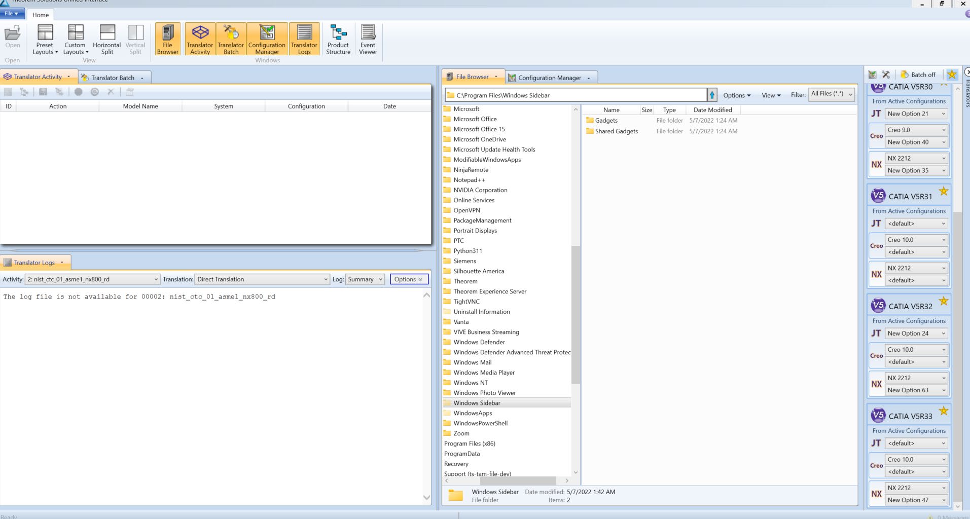
The default layout is split into 4 primary areas, which can be altered to the users prefer:
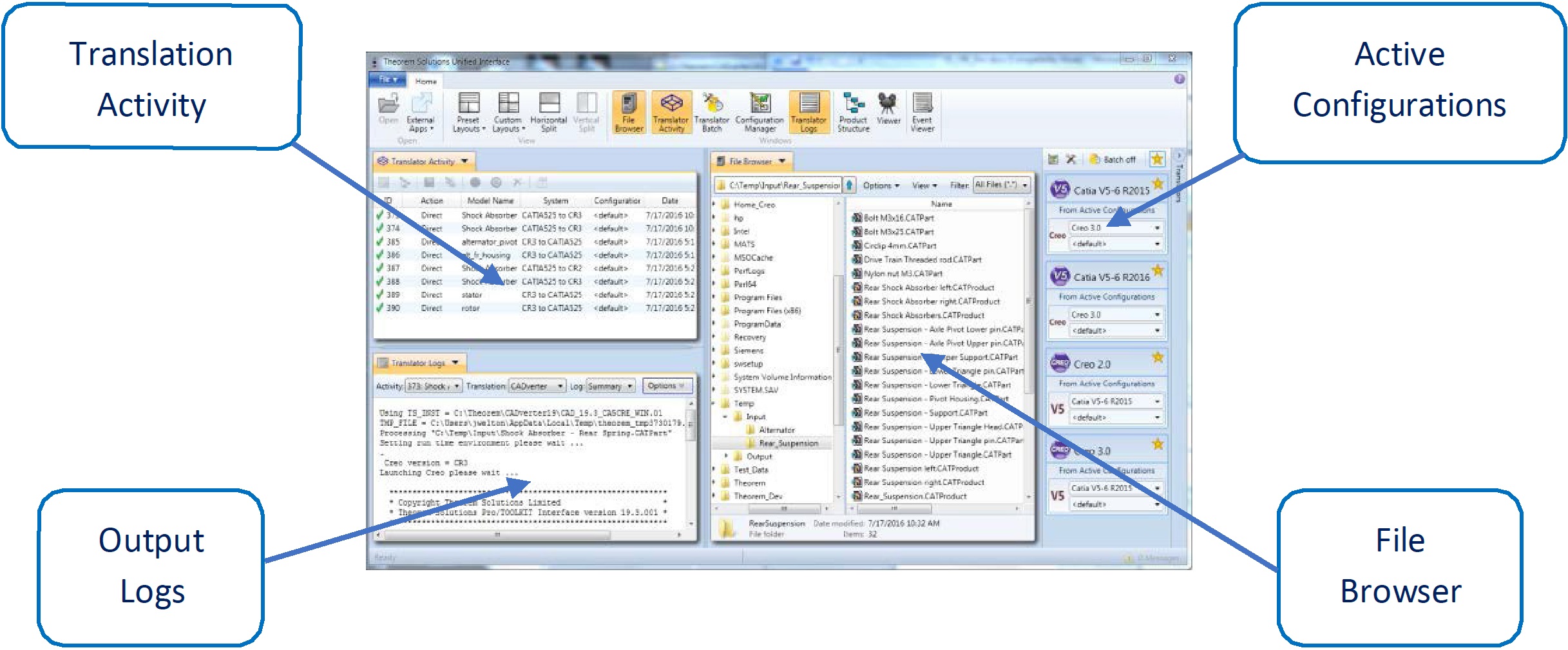
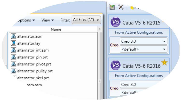
The simplest way to translate from CATIA V5 or CREO is to drag a file from the file Browser Pane on to the Active Configurations for the translation you require.
On completion, the Unified Interface will display the activity information and details from the log file created during the translation, if requested, in the Translation Activity and Output Log panes, respectively.
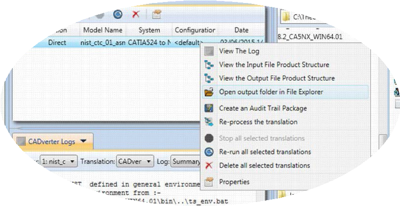
The generated output data can be located by selecting the translation from the Activity pane and opening the output folder.
Default Translation – via the Command Line
Running a translation via the command line can be carried out via the cad_run.cmd file
located in the <installation_directory>\bin directory. The format of the command is as
follows when translating from CATIA V5 to CREO:
<Translator_installation_directory>\bin\cad_run.cmd CATIA5[XX]_CR[Y] <input_file> <output_file>
The format of the command is as follows when translating from CREO to CATIA V5:
<Translator_installation_directory>\bin\cad_run.cmd CR[Y]_CATIA5[XX] <input_file> <output_file>Note
Replace the [XX] seen in the example with the version of CATIA V5 you are using and replace the [Y] with the version of Creo you are using. E.g. for CATIA V5-6R2020, change to CATIA530 and for CREO 6 change to CR6.

The example above will translate a CATIA V5 sample file provided within the installation and produce the following output to the target location. In this case:
C:\Temp\Rear_Suspension.asm
Default Translation – via the Interactive method
It is possible to run translations via the interactive method for V5 ↔ Creo using the Theorem menu within Creo. To do this launch the start up commands which will be on your desktop or install directory.
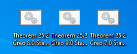
The next step would be once this is open within the main ribbon under Tools you will be able to Import or export from and to V5.

CADverter Customization
CADverter allows the information that is read from the source system and written to the target system to be tailored via a set of user specified arguments. Commonly used arguments are supported via the Unified Interface, with Advanced Arguments being described within this document for use in the Unified Interface or via the Command Line invocation.
Common Options for CATIA V5 to CREO
Within the Configuration Manager pane of the Unified Interface, arguments that can be specified when publishing CATIA V5 data into CREO are grouped into 4 areas:
CATIA V5 Read – Those arguments that affect how data is read from CATIA V5
CREO Write – Those arguments that affect how the data is written to CREO
Entity Mask – Those arguments that allow specific read entities to be masked
General – Those arguments that are common to ALL Publishing activities regardless of source data
CATIA V5 Read Arguments
The image below shows the CATIA V5 Read arguments that are available, with their default settings:
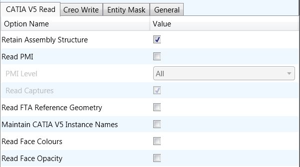
Each of these options is described below:
Option |
Description |
|---|---|
Retain Assembly Structure |
Maintain assembly structure in target file (Default is ON). Command Line Syntax:
|
Read PMI |
Enables PMI data read from the V5 file. (Default is OFF). Command Line Syntax:
|
PMI Level |
A secondary argument to ‘Read PMI’ and allows control of the level of PMI to be read. (Default is ALL when ‘Read PMI’ is marked as ON.) Options Available:
|
Read Captures |
A secondary argument to ‘Read PMI’ and allows the control over whether captures are read as part of the process. (Default is OFF) when ‘Read PMI’ is marked as ON. Command Line Syntax:
|
Read FTA Reference Geometry |
Enables reading of FTA Reference Geometry (Default is OFF). Command Line Syntax:
|
Maintain CATIA V5 Instance Names |
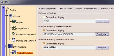
Honours CATIA V5 Tools->Options->Infrastructure->Product Structure->Nodes Customization panel settings (Default is OFF). Command Line Syntax:
|
Read Face Colours |
Read the face colours (Default is Off). Command Line Syntax:
|
Read Face Opacity |
Read the opacity of the face (Default is Off). Command Line Syntax:
|
CREO Write Arguments
The image below shows the Write CREO arguments that are available, with their default settings:
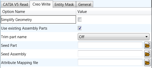
Each of these options is described below:
Option |
Description |
|---|---|
Simplify Geometry |
Attempt to write Analytical Geometry where possible (Default is Off). Command Line Syntax:
|
Use existing Assembly Parts |
If the output Folder already contains output Files of the same name, do not Overwrite those Files (Default is On). Command Line Syntax:
|
Trim part name |
If the part name is too long, use the first X characters and the final (30 - X) characters to reach the 30 character limit. (Default is off). Command Line Syntax:
|
Seed Part |
Use a Creo Seed Part file when creating the Creo output. Command Line Syntax:
|
Seed Assembly |
Use a Creo Seed Assembly file when creating the Creo output. Command Line Syntax:
|
Attribute Mapping File |
Select a standard property mapping file. Command Line Syntax:
|
CATIA V5 to CREO Entity Masking Arguments
The image below shows the Masking arguments that are available, with their default settings:
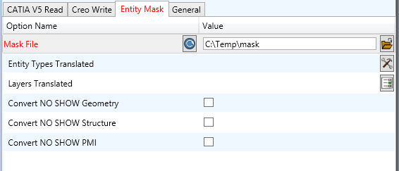
Each of these options is described below:
Option |
Description |
|---|---|
Mask File |
Specifies the Mask File to be written to, that can be referenced by future translations. A Mask file MUST be specified if masking is required. The first line in this file is OFF ALL ENT: Command Line Syntax:
|
Entity Types Translated |
Specifies a selection list from which to select which entity types are to be processed. The following types are available: “POI”,”CUR”,”SKI”,”SOL”,”ISO”,”TEX”,”AXI” Command Line Syntax:
|
Layers Translated |
Specifies a selection list from which to select which layers are to be processed. Command Line Syntax:
|
Convert NO SHOW Geometry |
Enables Hidden geometry to be processed (Default is Off). Command Line Syntax:
|
Convert NO SHOW Structure |
Enables Hidden Assembly Structure to be processed (Default is Off). Command Line Syntax:
|
Convert NO SHOW PMI |
Enables Hidden PMI to be processed (Default is Off). Command Line Syntax:
|
CATIA V5 to CREO General Arguments
The image below shows the General arguments that are available, with their default settings:
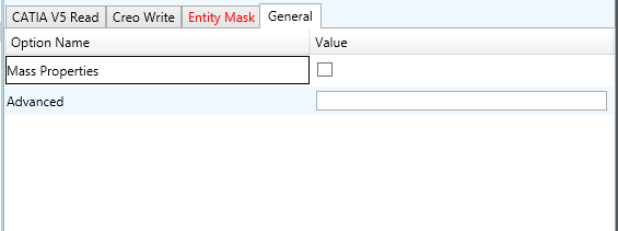
Each of these options is described below:
Option |
Description |
|---|---|
Mass Properties |
Allows Mass Property information to be read from the source data and written as attributes to the PDF document. Default is OFF. Command Line Syntax:
|
Advanced |
Allows any of the Command Line Advanced arguments documented below to be passed to the Unified Interface invocation. |
Common Options for CREO to CATIA V5
Within the Configuration Manager pane of the Unified Interface, arguments that can be specified when publishing CREO data into CATIA V5 are grouped into 3 areas:
CREO Read – Those arguments that affect how data is read from CREO
CATIA V5 Write – Those arguments that affect how the data is written to CATIA V5
General – Those arguments that are common to ALL Publishing activities regardless of source data
CREO Read Arguments
The image below shows the CREO Read arguments that are available, with their default settings:
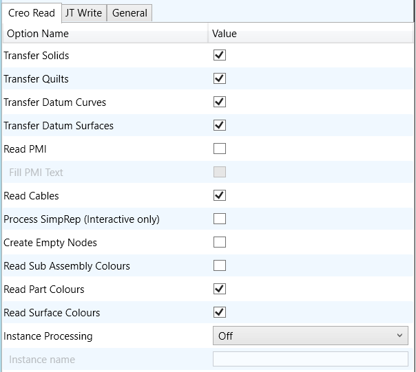
Each of these options is described below:
Option |
Description |
|---|---|
Transfer Solids |
Enables solid processing. (Default is on). Command Line Syntax:
|
Transfer Quilts |
Enables quilt processing. (Default is on). Command Line Syntax:
|
Transfer Datum Curves |
Enables Datum Curve processing. (Default is on). Command Line Syntax:
|
Transfer Datum Surfaces |
Enables Datum Surface processing. (Default is on). Command Line Syntax:
|
Read PMI |
Enables PMI processing. (Default is off). Command Line Syntax:
|
Fill PMI Text |
Enabled when ‘Read PMI’ is selected. Improves the quality of PMI, but increases output size and processing time. (Default is off). Command Line Syntax:
|
Read Cables |
Enables the reading of Cable data from Creo. (Default is off). Note that in the Creo Configuration Editor, the setting display_thick_cables should be set to yes. Command Line Syntax:
|
Process Simprep |
Enables the reading of a specified Simplified Representation. This is only available when processing data interactively and using the option via the Configuration Manager. Command Line Syntax:
|
Create Empty Nodes |
If a part is missing, create an empty leaf node for it. (Default is off). Command Line Syntax:
|
Read Sub Assembly Colours |
Read colour information set on sub-assembly level (Default is off). Command Line Syntax:
|
Read Part Colours |
Read colour information set on parts. (Default is on). Command Line Syntax:
|
Read Surface Colours |
Read colour information set on surfaces. (Default is on). Command Line Syntax:
|
Instance Processing |
Process a defined instance. Contains 3 options: (Not to be used in conjunction with Process Specified Instance). (Default is off).
|
Instance Name |
Enter the instance name to process. Only activates when ‘Process Specified Instance’ selected. |
CATIA V5 Write Arguments
The image below shows the CATIA V5 Write arguments that are available, with their default settings:
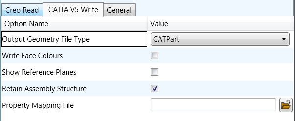
Each of these options is described below:
Option |
Description |
|---|---|
Output Geometry File Type |
Output Geometry file type (Default is CATPart – a CATProduct will be created for an assembly). Command Line Syntax:
|
Write Face Colours |
Processes Colours as applied to individual faces (Default is OFF). Command Line Syntax:
|
Show Reference Planes |
Creates reference planes. Default is OFF. Command Line Syntax:
|
Retain Assembly Structure |
Maintain assembly structure in derive output (Default is ON). Command Line Syntax:
|
Property Mapping File |
Assign a property mapping file. Command Line Syntax:
|
CREO to CATIA V5 General Arguments
The image below shows the General arguments that are available, with their default settings:
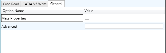
The option is described below:
Option |
Description |
|---|---|
Mass Properties |
Allows Mass Property information to be read from the source data and written as attributes to the PDF document (Default is off). Command Line Syntax:
|
Advanced |
Allows any of the Command Line Advanced arguments documented below to be passed to the Unified Interface invocation. |
Command Line Advanced Arguments
Any of the Advanced arguments can be added to the Command Line Invocation or to the General > Advanced field when run from within the User Interface.
Creo Arguments
Creo Argument |
Description |
|---|---|
|
Store non planar PMI graphics (leaders not in the plane of the annotation) |
|
Read multiple occurrences, eg support for occurrence PMI associations |
|
Reads PMI in lower level assembly parts |
|
Disable reading views with standard names (TOP, LEFT, etc). |
|
Supply a list of view names to be ignored |
|
Disables exploded views. |
|
Default: off Enable the processing of Part Level Views within an assembly. |
|
Process part level views and move into assembly space, such that only one part instance’s views are displayed. |
|
Default: off Enable the processing of PMI on parts within an assembly. |
|
Uses the part name in the view names to help identify the views when selected in PDF |
|
Default: hybrid Geometry grouped into assembly nodes for views is by default done on a view bases, which re-uses geometry where possible. This option creates a node for every item of geometry so that the views can hide/show them in the views. This can (depending upon the data and views) reduce the resulting file size and shorten the translation time, BUT in some cases the PDF is slow to respond due to the VIEW limitations. exploded - off – create a node per view with all geometry / wire etc for that view explode - on – create nodes for very solid / wireframe etc that can be referenced by views hybrid (default) – mixture of explode on/off – solids being exploded and wireframe grouped (best compromise) hybrid2 – as hybrid with points also grouped |
CATIA V5 Arguments
CATIA V5 Argument |
Description |
|---|---|
|
Converts curves to NURBS form |
|
Converts surfaces to NURBS form |
|
Read face opacity |
|
Sets the default to SOLID colours |
|
Reads hidden geometry / structure / pmi |
|
Allows sub-part specification tree information to be
read and presented to 3D PDF as product structure
information. This option also enables the |
|
CATIA V5 has a display mode that allows the display of shaded surfaces and edges. This option allows the translator to mimic this for FTA construction geometry by promoting the edge curves to standalone wireframe |
Large Assembly Processing
Overview
Large Assembly Processing (LAP) is available via command line only. Theorem’s LAP mechanism was designed to be a method to efficiently converting large assemblies into their target format.
This process differs from the standard CAD-to-CAD conversion method. The standard method opens the entire assembly into memory and converts the assembly into the target system. Whereas LAP employs a method to convert each assembly leaf node independently and then processes the top-level assembly using the already created component files.
LAP Advantages:
Consumes fewer system resources, RAM and CPU, thus allowing for larger assemblies to be processed on the same hardware.
Can be used as a troubleshooting mechanism as files which failed to convert can be re-translated with different options. This requires the assembly process to be run again to ensure the assembly contains these components.
LAP Disadvantages:
The use of LAP comes with the overhead of loading the libraries and licensing to convert each file independently. For this reason, the user may find that this process takes more time to complete.
LAP Process Overview
The LAP process begins with the user writing a “Wrapper Script.” This script is a windows batch
file that calls the initial translation using the assy_script argument. When this script runs, it will
output a number of Viewer files and a component script (batch file *.bat) to the specified
output folder. More details of the component script are provided in the applicable section.
A Viewer file is a Theorem proprietary file used as a temporary container for passing CAD information from the source to the target system. These files are maintained through the translation process. This can be useful if the translation is stopped and needs to be restarted. Using the existing Viewer files, the translation will continue from where it was stopped.
The component script, created by the wrapper script, contains a single line translation for each part file with the required translator arguments. This script can also be used to map the Viewer file names to the specified output file.
Once the part files have been created, the assemblies will be processed. Using the part files that were created when the component script ran, the assemblies are built using the transforms from the source CAD file. Thus ensuring all component files are at their proper location.
CATIA V5 to Creo
Review the “LAP Process Overview” section before continuing. This section outlines the process in detail.
The wrapper script will create three component batch scripts. The first is created to process CATIA V5 data to Viewer files. The name of this script is input_filename.vwr.bat. The second component script is to process the Viewer files to CREO. The name of this file is input_filename.vwr_2PROE.bat. The third script is input_filename.vwr_MOD.bat and is used during the update process, discussed later in this section.
Command Line Arguments
Argument |
Description |
|---|---|
|
Invokes the LAP process |
|
Translator arguments can be supplied for each leaf node conversion. Provides a method to supply different translator arguments which apply only to the component part level. e.g.: |
Example Wrapper Script
Note: The ^ symbol denotes continue to next line. Shown here to make the script easier to read, else it is a single line call to the translator.
C:\Program Files\Theorem\24.1\bin\cad_run.cmd ^
CATIA530_CR6 ^
C:\Temp\Input\Rear_Suspension\Rear_Suspension.CATProduct ^
C:\Temp\Output\Rear_Suspension\Rear_Suspension.prt ^
read_pmi_1 assy_script ^
as_leaf_node_args "read_pmi_1 dont_fill_pmi_text dont_fill_pmi_arrows"
Updating the Assembly
The following methods can be used to update an already translated assembly into the same output folder. Any new files will be created. All Transforms will be re-processed, so component placement will be correct.
To begin, delete or rename the Creo files and the corresponding Viewer files to be re-translated.
Set the environment variable TS_REM_OUT_EXISTING_PARTS=1 either in the
command prompt window used to run LAP or in the wrapper script. Then run the wrapper
script. For this process, the input_filename.vwr_MOD.bat will be used to recreate the required
Viewer files. Also, the input_filename.vwr_2PROE.bat will be recreated to only translate those
new Viewer files to CREO Part files.
When the translation is complete, the required component files have been recreated as well as the assembly files. The assembly files are processed to ensure any modification to the component transforms are honored.
Troubleshooting Files
One advantage to LAP is that each output file creates its own log file. This may make it easier to troubleshoot that individual file if it is found that it did not translate properly. The user must decide what arguments are to be added and if they are CATIA read or CREO write arguments, or both.
CATIA Read Arguments Only – Begin by deleting the Viewer file and the CREO part file. Edit the Wrapper script to apply new arguments, and then run the translation.
CREO Write Arguments Only – Begin by deleting or renaming the CREO file in the output folder. The input_filename.vwr_2PROE.bat file can be edited to comment out each part file which does not require a new translation. Then edit the translator options for those files to be processed again. Run the input_filename.vwr_2PROE.bat script.
Alternatively, the required component translation can be copied and pasted into a command prompt window. The translator arguments edited in this window and the translation processed.
Both CATIA Read and CREO Write Arguments – Begin by deleting the Viewer file and the CREO
part file. Edit the Wrapper script to apply new arguments. Be sure to use the
as_leaf_node_args to apply options, where required, to only the component part files. Then
run the wrapper script to begin the translation.
Creo to CATIA V5
Review the “LAP Process Overview” section before continuing. This section outlines the process in detail.
The wrapper script will create the component batch script. This script will contain the command line translation for all required part files.
Command Line Arguments
Argument |
Description |
|---|---|
|
Invokes the LAP process |
|
Translator arguments can be supplied for each leaf node conversion. Provides a method to supply different translator arguments which apply only to the component part level. e.g.: |
Example Wrapper Script
Note: The ^ symbol denotes continue to next line. Shown here to make the script easier to read, else it is a single line call to the translator.
C:\Program Files\Theorem\24.1\bin\cad_run.cmd ^
CR6_CATIA530 ^
C:\Temp\Input\Alternator\alternator.asm ^
C:\Temp\Output\Alternator\Alternator.CATProduct ^
no_datum_curves no_quilts no_datum_surfaces assy_script ^
as_leaf_node_args " surf_to_nurbs edge_to_nurbs "
If the translation is to be re-processed, the existing Viewer files will be used. To re-process the translation while overwriting the existing Viewer files, the following environment variable must be set:
TS_NO_USE_ASSY_TEMP_FILES=1
Updating the Assembly
The following methods can be used to update an already translated assembly into the same output folder. Any new files will be created. All Transforms will be re-processed, so component placement will be correct.
To begin, delete or rename the CATIA files to be re-translated. Either use the environment variable listed previously to overwrite the existing Viewer file, or delete the Viewer file prior to running the translation. If unsure which viewer file to remove, the Component Batch script will map each Viewer file to an output CATIA filename. Then run the translation again.
Troubleshooting Files
One advantage to LAP is that each output file creates its own log file. This may make it easier to troubleshoot that individual file if it is found that it did not translate properly. The user must decide what arguments are to be added and if they are CREO read or CATIA write arguments, or both.
CREO Read Arguments Only – Begin by deleting the Viewer file or setting the environment variable mentioned previously. Edit the Wrapper script to apply new arguments, and then run the translation.
CATIA Write Arguments Only – Find the file to be re-translated in the Component script. Edit the translator arguments. Either comment out all other lines (add REM to the beginning of the line) or copy the translation call and paste it into a command prompt window. Run the translation.
Both Read and Write Arguments – Begin by deleting the Viewer file or setting the environment
variable mentioned previously. Edit the Wrapper script. Be sure to add the required arguments to
the as_leaf_node_args portion. Run the translation.
CATIA V5 Configuration
Introduction
This Appendix details how to define and configure the CATIA V5 and Theorem environment to work together.
Conventions
Release of CATIA V5
To indicate a release of CATIA V5 the notation <XX> shall be used. This needs to be replaced with the specific release to be used i.e. 28, 29, 30, 31.
Platform specific directory
Within the installation directory of CATIA V5 there is a platform specific directory i.e.
win_b64. This directory shall be referred to as <OSDS> in this Appendix.
Theorem Installation directory
The Theorem translator installation directory is set at installation time in the translator
ts_env.bat file. This directory shall be noted as <%TS_INST%> in this Appendix.
CATIA V5 Installation Directory
Upon installation of a CATIA V5 product the user will be asked to specify the installation directory. This is the directory which contains the platform specific <OSDS> directory.
Having selected the CATIA V5 installation directory via the browse button, the installation
process will record the location of the CATIA V5 installation directory in the ts_env.bat file.
This file is located in the Theorem translator installation directory. If the location of CATIA V5
subsequently changes, the translator can be guided to the changed location by modifying this
file using a text editor to modify the ts_env.bat that is located in the translator installation
directory.
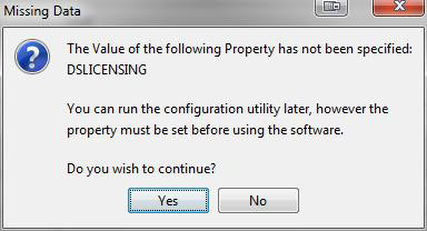
For CATIA V5 R22 and lower releases, a choice is available of using the older LUM Legacy licensing system or the new Dassault Licensing. To enable this enter LEGACY in the DSLICENSING option.
If no entry is included for DSLICENSING a warning dialog will be displayed which warns of the empty field. Selecting Yes to continue will allow the installation to continue.
Running CATIA V5 Translators
Before running the translator the user must run CATIA V5 interactively at least once to configure the CATIA V5 environment and license settings. This can be achieved by running the catia5r<XX>_start script as follows:
%TS_INST%\bin\catia5r<XX>_start.cmd
Once CATIA has been run the Translator can run as described in the relevant product User Guide.
CATIA V5 Environment DIRENV & ENV
The default location for CATIA V5 to store its global environment files is in the global directory:
Windows XP:
C:\Documents and Settings\All Users\Application Data\DassaultSystemes\CATEnv
Windows 7, 8 & 10:
C:\ProgramData\DassaultSystemes\CATEnvOr
%APPDATA%\CATEnv
You can find this location by running:
%CATIAV5_INST%\<OSDS>\code\bin\setcatenv -h
The environment files are named in the form CATIA.V5RN.B<XX>.txt
If when installing CATIA V5 the default environment file location was replaced with another
location then this location needs to be indicated to the CADverter by defining in the ts_env.bat
the environment variable CATIAV5_DIRENV:
set CATIAV5_DIRENV=/some/directory
If the Theorem installation is needed to support multiple releases of CATIA, then the user can define release specific locations using:
set CATIAV5R<XX>_DIRENV=/some/directory
The Theorem translator will attempt to create its own environment file called
TheoremCatia5R<XX>.txt. The user must therefore have write permission to the CATEnv
directory. If this is not possible an existing environment file can be specified using the variable
CATIAV5_ENV. e.g.
set CATIAV5_ENV=CATIA.V5R26.B26
Note: The extension .txt is not required. The user can specify a release specific name using
CATIAV5R<XX>_ENV e.g. set CATIAV5R25_ENV=CATIA.V5R26.B26
Checking the CATIA V5 Environment
A script is provided to check that the CATIA V5 environment is set up correctly. In a command window run the command script:
%TS_INST%\bin\checkcatia5r<XX>env.cmd