Visualization: Draw bounding box using markup model
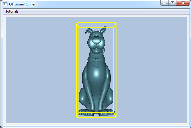
This tutorial shows how to create a data source by loading a VTFx file and drawing the models bounding box as a markup model.

After the unstructured grid model read from file is set up in the view, you can get the bounding box for this model with cee::vis::View::boundingBox(). Use the values from this bounding box to make a markup model for drawing a bounding box around the read model.
Load the file and setup the model specification to show the result. For a more thorough explanation on creating a data source from a file interface and setup the model specification, see the Load VFT tutorial: UnstructGrid: Load model from file and set up model specification
Note
This tutorial expect the application to have a correctly configured cee::vis::View in place. See demo applications on how to set up a cee::vis::View in your application.
Load model
Create the model and a VTFx file interface data source. Open the file and set the created data source in the model.
Set the first state as current.
    cee::PtrRef<cee::ug::UnstructGridModel> ugModel = new cee::ug::UnstructGridModel();
    cee::PtrRef<cee::ug::DataSourceVTFx> source = new cee::ug::DataSourceVTFx(42);

    cee::Str vtfxFile = TutorialUtils::testDataDir() + "scoobs.vtfx";
    if (!source->open(vtfxFile))
    {
        // VTFx file not found
        return;
    }

    ugModel->setDataSource(source.get());
Set the first state as current in the model specification.
    std::vector<cee::ug::StateInfo> stateInfos = source->directory()->stateInfos();
    if (stateInfos.size() > 0)
    {
        int lastStateId = stateInfos[stateInfos.size() - 1].id();
        ugModel->modelSpec().setStateId(lastStateId);
    }
Set up the created model
The model is ready to use and can be added to the view. Exactly where the view exists depends on the platform and solution. These examples uses Qt and the view is set up in a cee::qt::ViewerWidget.
    gcView->addModel(ugModel.get());

    ugModel->updateVisualization();
Create the markup model
Create the markup model object.
cee::PtrRef<cee::vis::MarkupModel> markupModel = new cee::vis::MarkupModel();
Get the bounding box from the view and get all vertices in the box.
    cee::BoundingBox bb = gcView->boundingBox();
    cee::Vec3d p1(bb.minimum().x(), bb.minimum().y(), bb.minimum().z());
    cee::Vec3d p2(bb.minimum().x(), bb.maximum().y(), bb.minimum().z());
    cee::Vec3d p3(bb.minimum().x(), bb.maximum().y(), bb.maximum().z());
    cee::Vec3d p4(bb.minimum().x(), bb.minimum().y(), bb.maximum().z());
    cee::Vec3d p5(bb.maximum().x(), bb.minimum().y(), bb.minimum().z());
    cee::Vec3d p6(bb.maximum().x(), bb.maximum().y(), bb.minimum().z());
    cee::Vec3d p7(bb.maximum().x(), bb.maximum().y(), bb.maximum().z());
    cee::Vec3d p8(bb.maximum().x(), bb.minimum().y(), bb.maximum().z());
Add all the lines of the bounding box to the model.
    cee::PtrRef<cee::vis::MarkupPartLines> part = new cee::vis::MarkupPartLines(cee::Color3f(1.0, 1.0, 0.0), 3, true, 0.0);
    part->add(p1, p2);
    part->add(p2, p3);
    part->add(p3, p4);
    part->add(p4, p1);
    part->add(p1, p5);
    part->add(p2, p6);
    part->add(p3, p7);
    part->add(p4, p8);
    part->add(p5, p6);
    part->add(p6, p7);
    part->add(p7, p8);
    part->add(p8, p5);
    markupModel->addPart(part.get());
Add the markup model to the view
gcView->addModel(markupModel.get());
Update the view.
    gcView->camera().fitView(bb, cee::Vec3d(0, 0, -1), cee::Vec3d(0, 1, 0));
    gcView->camera().inputHandler()->setRotationPoint(bb.center());

    gcView->requestRedraw();
See the complete source code here:
