
hc_proto.h
Macro Definitions
HC_PROTO_DEFINED |
Functions
Detailed Description
Function Documentation
-
void
HC_Abort_Program(char const *message) Prints an error message. Calls the defined exit handlers. Exits to the operating system with a final error status.
Provides an orderly way to terminate execution upon the discovery of an error.
- DETAILS
A standard HOOPS fatal error sequence is initiated. First, the currently defined error handlers are called. The list presented includes Report_Error() (unless you’ve specified otherwise), which causes message to be printed out where the user can see it. Then, the currently defined exit handlers are called, usually including Reset_System() . Finally, the operating system is called, with an “error” exit status, to terminate program execution.
See also
HC_Exit_Program, HC_Define_Exit_Handler, HC_Define_Error_Handler, HC_Report_Error
Parameters: message – A quoted string, or a string variable containing your error message. An empty string is permissible.
-
void
HC_Append_Modelling_Matrix(float const array[]) Allows direct manipulation of the matrix transform applied against all picture elements and subsegments in a segment.
Appends the explicitly provided transformation to the cumulative modelling transform of the currently open segment, or to the named segment(s). The visual effect is that of the scene as it was, then this change. (The old array is multiplied on the left by this new array.)
- DETAILS
Use this routine only if your program organizes and keeps track of the net transformations applied to your objects.
The array should be stored so the column varies faster than the row as you proceed through consecutive memory locations. In C and Pascal, the first index of the array is usually the row index and the second index is the column.
- NOTES
If there was no previous transform, this operation becomes a plain Set_Modelling_Matrix().
The first, second, and third rows of the fourth column of array must be zero - no “perspective” transformation is allowed. The fourth row of the fourth column is usually 1.0 (it must not be zero.)
See also
HC_Set_Modelling_Matrix, HC_Rotate_Object, HC_Translate_Object, HC_Scale_Object, HC_Set_Camera, HC_Orbit_Camera.
- RESTRICTIONS
Parameters: array – Transform matrix provided by the user. Passed by reference in all languages. May need to be transposed in languages other than C.
-
void
HC_DAppend_Modelling_Matrix(double const array[]) Similar to Append_Modelling_Matrix(), but accepts double-precision data.
See also
HC_Append_Modelling_Matrix
Parameters: array – Transform matrix provided by the user. Passed by reference in all languages. May need to be transposed in languages other than C.
-
void
HC_Append_Texture_Matrix(float const array[]) Allows direct manipulation of the matrix transform applied against all shell and mesh (u, v, w) vertex parameters and subsegments in a segment.
Appends the explicitly provided transformation to the cumulative texture transform of the currently open segment, or to the named segment(s). The visual effect is that of the scene as it was, then this change. (The old array is multiplied on the left by the new array.)
- DETAILS
Use this routine if your program organizes and keeps track of the net transformations applied to your vertex parameters.
The array should be stored so the column varies faster than the row as you proceed through consecutive memory locations. In C and Pascal, the first index of the array is usually the row index and the second index is the column.
- NOTES
If there was no previous transform, this operation becomes a plain Set_Texture_Matrix() .
The fourth row of the fourth column is usually 1.0 (it must not be zero.)
See also
HC_Set_Texture_Matrix, HC_Rotate_Texture, HC_Translate_Texture, HC_Scale_Texture.
- RESTRICTIONS
Parameters: array – Transform matrix provided by the user. Passed by reference always. May need to be transposed in languages other than C.
-
void
HC_Begin_Alias_Search(void) These routines recall the name of each alias.
This set of routines allows the user to “dump” all the aliases that exist in the database. It returns both the user defined aliases and those defined by the system (e.g.: “?include library”). It returns only the aliases names - to find out what their expansions are use Show_Alias(). For example:
- DETAILS
Begin_Alias_Search () while (Find_Alias (alias)) { Show_Alias (alias, def) print (alias, def) } End_Alias_Search ()
prints all the known aliases names and their definitions. Begin_Alias_Search() initiates the search for each alias name.
Show_Alias_Count() finds out how many aliases will be returned. This is useful for determining the size of a data structure needed to store incoming items.
Find_Alias() retrieves the alias names, one at a time. The function returns false when all aliases have been returned.
End_Alias_Search() terminates the sequence and frees any involved memory.
If an alias search is in progress and an alias becomes undefined (via UnDefine_Alias() ), it will not be returned by subsequent calls to Find_Alias(). If an alias is added, it will not be returned until the next alias search begins.
- NOTES
Show_Alias_Count() is only valid between Begin_Alias_Search() and End_Alias_Search(). It will always return the total number of aliases defined not the remaining number of aliases.
Alias searches can be nested. A user program can call Begin_Alias_Search() and look at the defined aliases without interfering with an alias search, which might have been activated by another portion of the program. When End_Alias_Search() is called, the previously active alias search (if any) becomes current.
See also
HC_Show_Alias, HC_Define_Alias, HC_Show_Pathname_Expansion
- RESTRICTIONS
-
void
HC_Begin_Callback_Name_Search(void) Finds the names of all previously defined callback routines.
These routines are used to find all the callback name definitions existing within the database. For example,
- DETAILS
Begin_Callback_Name_Search () while (Find_Callback_Name (name)) print (name) End_Callback_Name_Search ()
prints all the known callback definitions. Begin_Callback_Name_Search() initiates the search for callback name definitions. If you need to know how many callback definitions will be returned (possibly to allocate a sufficiently large data structure to hold the results), call Show_Callback_Name_Count() after initiating the search.
Find_Callback_Name() returns the names, one by one. This function returns false when all the definitions have been returned.
End_Callback_Name_Search() terminates the search. This last step can be done anytime after initiating the search.
If a callback search is in progress and a callback becomes undefined (via UnDefine_Callback_Name() ), it will not be returned by subsequent calls to Find_Callback_Name() . If a callback definition is added, it will not be returned until the next callback search is initiated.
- NOTES
Show_Callback_Name_Count() is only valid between Begin_Callback_Name_Search() and End_Callback_Name_Search() . It will always return the total number of callback names, not the remaining number of definitions.
Callback name searches can be nested. A user program can call Begin_Callback_Name_Search() and look at the defined callbacks without interfering with a callback search, which might be in progress. When End_Callback_Name_Search() is called, the previously active callback search is resumed.
See also
HC_Define_Callback_Name, HC_Show_Callback_Name.
-
void
HC_Begin_Color_Name_Search(void) These routines recall all the defined color names.
These routines are used to find all the color definitions in the database. For example,
- DETAILS
Begin_Color_Name_Search () while (Find_Color_Name (first, second, third) print (first, second, third) End_Color_Name_Search ()
prints all the known names, in the style in which they were originally defined. Begin_Color_Name_Search() initiates the search for color names.
If you need to know how many color definitions will be returned (possibly for allocating a data structure to hold them) call Show_Color_Name_Count() after initiating the search.
Find_Color_Name() returns the names (one set at a time). The function returns false when all color names have been returned.
End_Color_Name_Search() terminates the process and frees any involved memory. This last step can be done any time after the initial call to Begin_Color_Name_Search().
If you want to examine the color name definitions, call Parse_String() (to take out the commas) on the results of Find_Color_Name(). Then call Show_Color_Name() on each name.
- NOTES
After calling Begin_Color_Name_Search(), if a color becomes undefined (via UnDefine_Color_Name() ), subsequent calls to Find_Color_Name() will not return it. If a color is redefined, the new definition will be returned. If a new color is defined, it will not be returned in this search sequence.
Show_Color_Name_Count() is only valid between Begin_Color_Name_Search() and End_Color_Name_Search() . It will always return the total number of colors defined, not the remaining number of color definitions.
Color name searches can be nested. A user program can call Begin_Color_Name_Search() and look at the defined color names without interfering with a color name search, which might have been activated by another portion of the program. When End_Color_Name_Search() is called, the previously active color name search (if any) becomes current.
See also
HC_Define_Color_Name, HC_Show_Color_Name, HC_Parse_String
-
void
HC_Begin_Contents_Search(char const *segment, char const *filter) These routines are used to “dump” the contents of a segment or certain types of geometry.
Many user applications must manipulate the geometry in the database to perform some type of analysis. For example, if a program needs to calculate the areas of all polygons in a segment, it would need to know the coordinates of the points in each polygon. A contents search (specifically, Find_Contents()) can be used to retrieve the keys of all of the polygons, and then Show_Polygon() can be used to extract the points.
- DETAILS
In a contents search, Begin_Contents_Search() initiates and defines the search. Only the types specified in filter are used in the search, and only the segment or geometry specified in segment are checked.
Show_Contents_Count() determines the number of entities returned. This is useful for determining the size of a data structure needed to store the incoming items.
Find_Contents() returns entities, one at a time, from the selected segment or geometry. Find_Contents returns a type (i.e. “window frame”) and, if appropriate, a key. (Geometry, segments, includes, and styles have keys. Attributes do not have keys.) The return value is false when all items have been returned.
End_Contents_Search() terminates the search sequence.
As with the other search routines, Begin_Contents_Search() operations can be nested. This feature can be used, for example, to “walk the tree” as sub-segments are encountered. A call to End_Contents_Search() terminates the current search context (segment specification and filter) and reactivates the previously active context (if any).
The segment parameter can take a number of valid location specifications including aliases, wildcards, and paths, as explained in the HOOPS/3dGS Programming Guide section on segment name syntax (see Fundamentals > Database Structure). The following are examples of valid usage:
- “.” Searches the currently open segment.
- “..” Searches the parent of the currently open segment.
- “…” Searches the currently open segment and its child segments.
- “….” Searches the currently open segment, its children, and any include segments below the current segment.
- “?picture/model” Searches the segment “model”.
- “?picture/model/…” searches the segment named ‘model’ and all of its subsegments.
- “?picture/model/….” Searches the segment named ‘model’, all of its children, and any include segments below ‘model’.
- “/…/model*” Searches all segments in the entire tree starting with ‘model’, but not their subsegments.
- Geometry that can be inserted such as “images, lights, lines, markers, meshes, polygons, polylines, shells, string cursors, text”.
- One of the attributes that can be set such as “color”, “marker size”, “color map”, “streaming mode”, etc. Attribute filters may be refined by adding sub-options to the string, such as “color=(lines)”, “user options = cost” or “visibility=faces”.
- The word “geometry” matches all types of geometry.
- The word “attributes” matches all attributes.
- The word “style” matches style references.
- The types “segment” and “include” match, respectively, child segments and “include references” to segments.
- The word “subsegment” matches “segment” and “include”.
- The word “inked line” selects the “currently being inked in” polyline (if any).
- The word “ordered” returns only geometry brought to the front by Bring_To_Front() . The items are returned in drawing order. Successively returned items are drawn on top of previously returned items when the scene is updated.
- The word “everything”, matches all types.
- The word “self”, matches the subsegments themselves in a recursive search. This differs from the “subsegment” keyword in that it returns the parent instead of the children.
- Any of the above types with “no” in front of them. For example: “everything, no geometry, no windows, no color maps” selects all types except windows, color maps, and all types of geometry. If specifications overlap (as in “geometry, no lines”), the last specification wins.
- The word “hardware resources” matches display lists, textures, and vertex arrays that exist on the video card’s cache.
- The word “follow references” means the search will dig through references as part of the search. Without it, you’d have to search for references explicitly, find what they’re pointing at and do a new search there.
Additional types accepted by this function are:
“distant light”, “local light”, “spot light”, “area light”, “includer”, “styler”, “style”, “color”, “callback”, “camera”, “clip
region”, “handedness”, “selectability”, “visibility”, “window”, “window frame”, “color map”, “driver”, “driver options”, “edge
pattern”, “edge weight”, “face pattern”, “heuristics”, “line pattern”, “line weight”, “marker size”, “marker symbol”, “metafile”, “modelling matrix”, “rendering options”, “text alignment”, “text font”, “text leader”, “text path”, “text spacing”, “texture matrix”, “user value”, “window pattern”, “texture definition”, “local texture”, “glyph definition”, “line pattern
definition”, “line style definition”, “condition”, “streaming mode”, “circle”, “circular arc”, “circular chord”, “circular
wedge”, “cutting plane”, “cutting section”, “light”, “ellipse”, “elliptical arc”, “grid”, “line”, “marker”, “mesh”, “image”, “pixel array”, “polyline”, “polygon”, “shell”, “string cursor”, “text”, “nurbs curve”, “nurbs surface”, “cylinder”, “polycylinder”, “sphere”, “include”, “reference geometry”, “user options”
The following code example sums the areas of all polygons in all segments that contain the word “plate”. It assumes the existence of a user written function that returns the area of a polygon given its key.
sum = 0.0 Begin_Contents_Search("/...*plate*", "polygons") while (Find_Contents (type, poly)) sum = sum + polygon_area(poly) End_Contents_Search()
The “type” variable in this example will always be given the value “polygon”.
The segment name passed to Begin_Contents_Search() can contain wildcards, a list of segments or both. In this case, subsequent calls to Find_Contents() do not distinguish which segment contains each object. Use Show_Owner_By_Key() to determine this. Also, when multiple segments are specified, the type “ordered” does not distinguish which objects in the segments will be drawn first.
The returned types are entirely lowercase and singular, for example: “line”, “selectability”, “polygon”. Normally, you would look at the type and make other calls ( Show_Visibility() , Show_Polyline() , etc.) to get more details about the object whose key was returned.
If an object satisfying the target specification is deleted while a segment search is in progress, it will not be returned by Find_Contents() . If a segment is renamed, the new name will be returned. If geometry is moved to a new segment, its key will be returned even if the new segment name no longer matches the original search specification. If an object is created after a call to Begin_Contents_Search(), it will not be returned in the current sequence of Find_Contents() calls.
- NOTES
Show_Contents_Count() is only valid between Begin_Contents_Search() and End_Contents_Search(). It will always return the total number of items not the remaining number of items.
The inked line returned from a streaming segment will contain only the portion added since the last “Set” command changed any attribute in that segment.
When “hardware resources” are found by Begin_Contents_Search, Find_Contents always returns -1. In other words, hardware resources have no keys associated with them. Shells and meshes can be opened and have their hardware resources flushed, but all other types of geometry (e.g. lines, polylines polycylinders and images) must have their hardware resources flushed from either their owning segment or some segment above.
See also
HC_Begin_Segment_Search, HC_Show_Existence, HC_Show_Key_Type, HC_Show_Segment, HC_Show_Owner, HC_Show_Polyline, HC_Show_Shell, HC_Show_Marker.
Parameters: - segment – A string specifying the location(s) of the search.
- filter – List of the types of objects you’re interested in.
-
void
HC_Begin_Font_Search(char const *display, char const *filter) Finds the names of all the fonts available on a particular device.
Begin_Font_Search() initiates and defines the search. Only the types specified in filter are searched for.
- DETAILS
- A font search allows you to find out what fonts are available on a given display.
Show_Font_Count() determines the number of font names returned. This is useful for determining the size of a data structure needed to store the incoming items.
Find_Font() returns names, one at a time, from the selected display. The return value becomes false when all items have been returned.
End_Font_Search() terminates the search sequence. As with the other search routines, the Begin_Font_Search() operations can be nested.
The following choices are available for filter:
“Generic” tells you which of the generic font names (see Set_Text_Font() ) are available - in at least one size.
“Specific” tells you which individual fonts are available, with the names coming back in the style of the local system (for example, the operating system).
“Defined” tells you which user defined fonts are available, with the names coming back in the previously defined form.
“Family” or “families” tells you which name the system, or HOOPS, has picked to refer to the available sizes of a single typeface.
Any combination of choices can be given. Separate by commas. Uppercase versus lowercase is not important.
If you need more than the name of a font, call Show_Font_Info() to get additional details.
A simple coding example is:
Begin_Font_Search ("?Picture", "generic") while (Find_Font (name)) print ("Yes,?Picture has: ", name) End_Font_Search ()
If the device is not operating, Begin_Font_Search() might force a call to Update_Display() to get it started. See the note at the bottom of Show_Device_Info() for more information.
- NOTES
Show_Font_Count() is only valid between Begin_Font_Search() and End_Font_Search(). It will always return the total number of items, not the remaining number of items.
See also
HC_Define_Font, HC_Show_Font, HC_Show_Font_Info, HC_Set_Text_Font, HC_Show_Device_Info.
Parameters: - display – Name of the segment connected to the display of interest. Often “?Picture” or “?Hardcopy”.
- filter – A list of restrictions on the fonts of interest.
-
void
HC_Begin_Glyph_Search(void) These routines recall all the defined glyph names.
These routines are used to find all of the glyph definitions that exist in the database. For example,
- DETAILS
Begin_Glyph_Search () while (Find_Glyph (the_name)) Show_Glyph(the_name, definition) End_Glyph_Search ()
retrieves all the known names, in the style in which they were originally defined. If you need to know how many glyph definitions will be returned (possibly for allocating a data structure to hold them) call Show_Glyph_Count() after initiating the search.
Find_Glyph() returns the names (one at a time). The function returns false when all glyph names have been returned.
End_Glyph_Search() terminates the process and frees any involved memory. This last step can be done any time after the initial call to Begin_Glyph_Search().
After calling Begin_Glyph_Search(), if a glyph becomes undefined (via UnDefine_Glyph()), subsequent calls to Find_Glyph() will not return it. If a glyph is redefined, the new definition will be returned. If a new glyph is defined, it will not be returned in this search sequence.
- NOTES
- If you want to examine the glyph name definitions, call Show_Glyph() on the results of Find_Glyph() .
Show_Glyph_Count() is only valid between Begin_Glyph_Search() and End_Glyph_Search(). It will always return the total number of glyphs defined as opposed to the remaining number of glyph definitions.
Glyph name searches can be nested. A user program can call Begin_Glyph_Search() and look at the defined glyph names without interfering with a glyph name search that might already have been activated by another portion of the program. When End_Glyph_Search() is called, the previously active glyph name search (if any) becomes current.
See also
HC_Define_Glyph, HC_Show_Glyph, HC_Parse_String
-
void
HC_Begin_Line_Style_Search(void) These routines recall all the defined line style names.
These routines are used to find all of the line style definitions that exist in the database. For example,
Begin_Line_Style_Search () while (Find_Line_Style (the_name)) Show_Line_Style(the_name, definition) End_Line_Style_Search ()
- DETAILS
retrieves all the known names, in the style in which they were originally defined. If you need to know how many line style definitions will be returned (possibly for allocating a data structure to hold them) call Show_Line_Style_Count() after initiating the search.
Find_Line_Style() returns the names (one at a time). The function returns false when all line style names have been returned.
End_Line_Style_Search() terminates the process and frees any involved memory. This last step can be done any time after the initial call to Begin_Line_Style_Search().
If you want to examine the line style name definitions, call Show_Line_Style() on the results of Find_Line_Style() After calling Begin_Line_Style_Search() , if a line style becomes undefined (via UnDefine_Line_Style() ), subsequent calls to Find_Line_Style() will not return it. If a line style is redefined, the new definition will be returned. If a new line style is defined, it will not be returned in this search sequence.
- NOTES
Show_Line_Style_Count() is only valid between Begin_Line_Style_Search() and End_Line_Style_Search() . It will always return the total number of line styles defined as opposed to the remaining number of line style definitions.
Line_Style name searches can be nested. A user program can call Begin_Line_Style_Search() and look at the defined line style names without interfering with a line style name search that might already have been activated by another portion of the program. When End_Line_Style_Search() is called, the previously active line style name search (if any) becomes current.
See also
HC_Define_Line_Style, HC_Show_Line_Style, HC_Parse_String
-
void
HC_Begin_Open_Segment_Search(void) Returns the pathnames of all open segments.
These routines are used to indicate all the segments that have been opened but not closed. A call to Begin_Open_Segment_Search() initiates the process. Each call to Find_Open_Segment() returns the pathname of a single open segment starting with the currently open segment (the most recently opened segment) and ending with the least recently opened segment. End_Open_Segment_Search() terminates the sequence and allows another series of open segment searches to be initiated.
- DETAILS
Once Begin_Open_Segment_Search() is called, Show_Open_Segment_Count() can be used to return the total number of open segments. This routine is useful for sizing an array large enough to hold all the pathnames returned by a sequence of calls to Find_Open_Segment() .
Once Begin_Open_Segment_Search() is called, all currently open segments will be returned by Find_Open_Segment() even if they are closed in the meantime. However, if any open segments are closed and then deleted, they will not be returned. Any open segments that are renamed will be returned with the new name.
- NOTES
- You can use these routines with no segments open. The first call to Find_Open_Segment() will just return false.
Show_Open_Segment_Count() is only valid between Begin_Open_Segment_Search() and End_Open_Segment_Search() . It will always return the total number of open segments, not the remaining number of open segments.
Open segment searches can be nested. A user program can call Begin_Open_Segment_Search() and look at the open segments without interfering with an open segment search, which might have been activated by another portion of the program. When End_Open_Segment_Search() is called, the previously active open segment search (if any) becomes current.
See also
HC_Begin_Contents_Search, HC_Begin_Segment_Search, HC_Open_Segment.
-
void
HC_Begin_Segment_Search(char const *segspec) Finds all segments matching a search specification.
Begin_Segment_Search() initiates the search by specifying where to start looking for segments.
- DETAILS
- The segment search routines provide the ability to determine the current segment structure of the database.
Show_Segment_Count() lets a program anticipate how many segments names will be returned from a sequence of calls to Find_Segment() in order that sufficient space may be allocated to receive them. Count is the total number of matching segments.
Find_Segment() is the routine that returns, one at a time, the segments which matched the specification given in Begin_Segment_Search(). When all segments have been returned, its function value becomes false.
End_Segment_Search() terminates the search sequence and reactivates any previously active segment search.
The segspec parameter can take a number of valid segment name specifications including aliases, wildcards, and paths, as explained in the HOOPS/3dGS programming guide section 1.2.6 “Segment-Name Syntax”. Wildcards in the segment specification will typically match more than one segment in the database. The following examples are valid usages:
- “*” Returns the currently open segment and all children, but no grandchildren.
- “.” Returns the currently open segment.
- “..” Returns the parent of the currently open segment.
- “…” Returns the currently open segment, and all subsegments.
- “….” Returns the currently open segment, all subsegments, and any include segments below the current segment.
- “?picture/model” Returns the segment “model”.
- “?picture/model/..” Returns “?picture”.
- “?picture/model/…” Returns the segment named ‘model’ and all of its subsegments.
- “?picture/model/….” Returns the segment named ‘model’, all of its children, and any include segments below ‘model’.
- “/…/model*” Returns all segments in the entire tree starting with ‘model’, but not their subsegments.
- “/…/model/….” Searches all segments in the entire tree named ‘model’, their children, and any include segments below them.
level = 0 print_children (segment) { Open_Segment (segment) Begin_Segment_Search ("*") while (Find_Segment (child)) { Parse_String (child, "/", -1, pathname) print (level, pathname) level = level + 1 print_children (pathname) level = level - 1 } End_Segment_Search () Close_Segment () }
This example could also have been written using the “contents search” routines, replacing “Begin_Segment_Search (“*”)” with “Begin_Contents_Search (“.”, “segments”)”, and so on.
If a search is in progress and a segment satisfying the target specification is deleted, it will not be returned by subsequent calls to Find_Segment() . If a segment is renamed, the new name will be returned. If a segment is created, it will not be returned in the current sequence of Find_Segment() calls.
- NOTES
- If no segments are found that match the specification, the first call to Find_Segment() returns false.
Show_Segment_Count() must be called between Begin_Segment_Search() and End_Segment_Search() . It will always return the total* number of segments, not the remaining number of segments.
See also
HC_Begin_Contents_Search, HC_Begin_Open_Segment_Search, HC_Show_Existence, HC_Open_Segment.
Parameters: segspec – A specification, often including wildcards, of the segment(s) to be searched for. Passed by reference always
-
void
HC_Begin_Shader_Search(char const *search) These routines recall the name of each shader.
Begin_Shader_Search () while (Find_Shader (shader)) { Show_Shader (shader, def, source) print (shader, def, source) } End_Shader_Search ()
- DETAILS
- This set of routines allows the user to “dump” all the shaders that exist in the database. It returns only the shader names. To find the details for each shader use Show_Shader(). For example:
…prints all the known shader names, their options and source. Begin_Shader_Search() initiates the search for each shader name.
Find_Shader() retrieves the shader names, one at a time. The function returns false when all shaders have been returned.
End_Shader_Search() terminates the sequence and frees any involved memory.
See also
HC_Show_Shader, HC_Define_Shader
- NOTES
- If a shader search is in progress and an shader becomes undefined via UnDefine_Shader(), it will not be returned by subsequent calls to Find_Shader(). If a shader is added, it will not be returned until the next shader search is begun.
Parameters: search – A specification of which custom shader implementation to search for: either “legacy” or “modern”.
-
void
HC_Begin_Shape_Search(void)
-
void
HC_Begin_Texture_Search(void) These routines recall all the defined texture names.
NOTES
These routines are used to find all of the texture definitions that exist in the database. For example:
Begin_Texture_Search () while (Find_Texture (the_name)) Show_Texture(the_name, definition) End_Texture_Search ()
…retrieves all the known names, in the style in which they were originally defined. If you need to know how many texture definitions will be returned (possibly for allocating a data structure to hold them) call Show_Texture_Count() after initiating the search.
Find_Texture() returns the names (one at a time). The function returns false when all texture names have been returned.
End_Texture_Search() terminates the process and frees any involved memory. This last step can be done any time after the initial call to Begin_Texture_Search().
If you want to examine the texture name definitions, call Show_Texture() on the results of Find_Texture().
After calling Begin_Texture_Search() , if a texture becomes undefined (via UnDefine_Texture() ), subsequent calls to Find_Texture() will not return it. If a texture is redefined, the new definition will be returned. If a new texture is defined, it will not be returned in this search sequence.
Show_Texture_Count() is only valid between Begin_Texture_Search() and End_Texture_Search(). It will always return the total number of textures defined as opposed to the remaining number of texture definitions.
Texture name searches can be nested. A user program can call Begin_Texture_Search() and look at the defined texture names without interfering with a texture name search that might already have been activated by another portion of the program. When End_Texture_Search() is called, the previously active texture name search (if any) becomes current.
See also
HC_Define_Texture, HC_Show_Texture, HC_Parse_String.
-
void
HC_Begin_Local_Texture_Search(void) Begins a texture search on the currently open segment.
Begin_Local_Texture_Search() is similar to Begin_Texture_Search() , but operates only on the currently open segment. To find all textures with this function, use the following method:
HC_Begin_Contents_Search("/...", "segments"); while (HC_Find_Contents(type, &segKey)) { HC_Open_Segment_By_Key(segKey); HC_Show_Segment (segKey, pathname); HC_Begin_Contents_Search (".", "attributes"); while (HC_Find_Contents(type, &tempKey)){ if (!strcmp (type, "texture definitions")) { HC_Begin_Local_Texture_Search(); HC_Show_Texture_Count(&texture_count); HC_Find_Texture (texture_name); } } } HC_End_Contents_Search();
- DETAILS
See also
HC_Begin_Texture_Search
- NOTES
- This behaves in a very similar fashion to Begin_Texture_Search() except that it only looks for locally defined textures. Also, since local textures are connected to a segment you must provide a segment from which the search should begin.
-
void
HC_Bring_To_Front(char const *segment) - Deprecated:
This function has been deprecated. It is superseded by setting the hsra rendering option to priority.
If the subject of a call to Bring_To_Front() , specified either by key or by name, is a segment that has a Window attribute, then you’re effectively asking to rearrange windows. A windowed segment that lies within a windowed segment is always drawn “on top” of the containing window. But when windowed segments lie side-by-side in the segment tree - when neither window is the owner of the other - the situation becomes ambiguous. If such windows don’t overlap no problem arises. If they do overlap, Bring_To_Front() allows for making a choice. Set_Window() automatically calls Bring_To_Front() for each newly-created window, so the default is “newest in front.” You might make an explicit call when, for example, the user’s interest has shifted from one window to another. This is often indicated by some action such as touching a rear window. In summary, Bring_To_Front() can be used to specify the precedence of overlapping sibling windows.
- DETAILS
- This function forces a particular drawing order onto a collection of geometric primitives. Since it does not change depth values, however, it has only minor effects on scenes with hidden surface removal algorithms (e.g. z-buffer, the default).
If, on the other hand, the subject of a call to Bring_To_Front() is something other than a windowed segment - if it’s geometry or a non-windowed segment - then you’re forcing a particular drawing order onto the system. You would do this if you want to manually describe what’s to have the appearance of being in front. Forcing a drawing order is sometimes more efficient than using the system’s hidden-surface algorithm. It might be suitable for a paint program in which the user selects precedence, or useful for putting “annotations” on a scene that is otherwise all hidden-surfaced. You should not use Bring_To_Front() if you don’t really care about the ordering. The system works more efficiently if it is permitted to order objects as it pleases.
Using Bring_To_Front() on 3-D geometry and nonwindowed segments only works within those segments where the “hidden surfaces” heuristic is not in effect. Hidden surfaces take priority over bring-to-front. So, to mix hidden-surface items and bring-to-front items in the same scene, do something like the following:
Open_Segment ("window") Set_Heuristics ("no hidden surfaces") Open_Segment ("A") Set_Heuristics ("hidden surfaces") // regular hidden-surface picture, as needed Close_Segment () Open_Segment ("B") Set_Heuristics ("hidden surfaces") // regular hidden-surface picture, as needed Close_Segment () // now make "A" completely in front of "B"... Bring_To_Front ("A") Close_Segment ()
Note that “A” or “B” could have elected to continue with “no hidden surfaces”. It might also make sense, depending on what “A” and “B” are, to turn off lighting visibility in one or the other. In addition, Bring_To_Front() can only be applied to siblings “A” versus “B.” Bring_To_Front() does not apply to parent-child relationships.
This function can help resolve situations that arise with z-buffering where two surfaces have identical depth values but it is known which is supposed to be on top. For example, highlighting can be done this way, by drawing an extra copy with different attributes. This, combined with Control_Update() can be a powerful technique to highlight and de-highlight subsets of shells without ever incurring full updates.
- NOTES
- If the object of the bring-to-front is a non-windowed segment or an include reference, the effect is of bringing forward that collection of geometry as a whole.
Once something has been brought-to-front there is no simple way to put it back where it was. More objects can be put in front of the first, though, and the system will remember the entire ordering.
If the wildcard construction is used on Bring_To_Front() (segment) and there are conflicts, the system’s choice of who really gets to be the one in front will not be predictable.
Entities within a streaming-mode segment can not be “brought-to-front”.
Bring_To_Front() only works on the local level of the segment tree. If window A contains window B which contains window *C, a bring-to-front of C will make C the foremost of all the windows within B. It won’t make B foremost of the windows within A. If you want that to be true say so, separately.
If polygons are displayed with no explicit drawing order (without hidden surfaces and without an explicit Bring_To_Front() ) and a “scoped” refresh happens (for example, a window-system window is removed from on top of half the HOOPS scene), the scoped refresh may redraw its part of the scene in a different order than the original. This causes an obvious suture line.
- RESTRICTIONS
See also
HC_Set_Window, HC_Set_Heuristics, HC_Set_Streaming_Mode, HC_Set_Camera, HC_Set_Visibility.
Parameters: segment – Name of the segment(s) to be shuffled forward.
-
void
HC_Bring_To_Front_By_Key(Key key) Similar to Bring_To_Front(), but operates on an object referenced by an HC_KEY.
- Deprecated:
This function is deprecated.
See also
HC_Bring_To_Front()
Parameters: key – Open_Segment() , or any Insert routine.
-
void
HC_Close_Edge(void) Closes the session that began with an opening call to Open_Edge().
See also
HC_Open_Edge()
-
void
HC_Close_Face(void) Closes the session that began with an opening call to Open_Face().
See also
HC_Open_Face()
-
void
HC_Close_Geometry(void) Closes the session that began with an opening call to Open_Geometry().
See also
HC_Open_Geometry()
-
void
HC_Close_LOD(void) Closes the session that began with an opening call to Open_LOD().
See also
HC_Open_LOD()
-
void
HC_Close_Region(void) Closes the session that began with an opening call to Open_Region().
See also
HC_Open_Region()
-
void
HC_Close_Segment(void) Closes the currently open segment.
See also
HC_Open_Segment, HC_Rename_Segment, HC_Flush_Contents, HC_Reset_System
- DETAILS
- Closes the currently open segment (i.e., the most recently opened segment), which is then no longer ready and available for “Insert” and “Set” operations. If there was a previously open segment, that segment becomes current once again. There must (eventually) be a matching Close_Segment() for every Open_Segment() , but in between as many Open’s and Close’s and even Update’s as you please can occur.
-
void
HC_Close_Vertex(void) Closes the session that began with an opening call to Open_Vertex().
See also
HC_Open_Vertex()
-
bool
HC_Compile_Shader(int key_count, Key const path_keys[], char const *options) Defines a section of code that will be injected into HOOPS 3DF shaders.
The geometry suboption needs to be the type of geometry which we want to see the shader for, optionally followed by a filter to limit generation to a particular set of primitives. For example, you could specify “geometry = (shell = triangles)” to get only the triangle shader for the shell, “geometry = (shell = (lines, points))” to get only the lines and points shaders for the shell, or “geometry = shell” to get triangle, lines, and points shaders for shells. The following is a list of geometry choices with the primitive types they may generate:
- “nurbs curve” - “lines”
- “elliptical arc” - “lines”
- “circular arc” - “lines”
- “line” - “lines”
- “polyline” - “lines”
- “polygon” - “triangles”, “lines”
- “circular chord” - “triangles”, “lines”
- “circular wedge” - “triangles”, “lines”
- “ellipse” - “triangles”, “lines”
- “circle” - “triangles”, “lines”
- “marker” - “points”
- “shell” - “triangles”, “lines”, “points”
- “mesh” - “triangles”, “lines”, “points”
- “cylinder” - “triangles”, “lines”
- “polycylinder” - “triangles”, “lines”
- “sphere” - “triangles”, “lines”
- “nurbs surface” - “triangles”, “lines”
- “text” - “triangles”, “lines”
- “grid” - “triangles”, “lines”, “points”
- “infinite line” - “lines”
- “image” - “triangles”
- Supported Options:
- geometry, stage, vertex format
- DETAILS
- [all] geometry
[all] stage [vertex | pixel]
The stage suboption will be either vertex or pixel if you wanted to restrict the shaders that are generated to a particular stage.
vertex format
The vertex format suboption can have the following options:
- “position” - [on | off]
- “double position” - [on | off]
- “normals” - [on | off]
- “diffuse” - [on | off]
- “specular” - [on | off]
See also
HC_Show_Compilation_Results_Size, HC_Show_Compilation_Results
Parameters: - key_count – The number of keys in the path
- path_keys – An array of keys, from the target segment up to a driver. Also possible to pass a single segment key
- options – A quoted string or a string variable containing a list of the desired options
Returns: true if it was able to find a custom shader on the given path for either the vertex or pixel shader and geometry, construct the shader source for any relevant primitive types, invoke the shader compile function, and the compilation is successful. Returns false otherwise.
-
bool
HC_Compute_Circumcuboid(char const *segment, Point *min, Point *max) Returns points defining a cuboid that circumscribes the geometry within a segment.
This function returns the axis-aligned bounding cuboid associated with a database entity. The bounding volume returned is computed on demand - it does not reflect the bounding volume stored at the segment, if any. The routine, Show_Bounding_Cuboid() , can be used for that purpose. The volume returned is expressed in oru.
- DETAILS
Compute_Circumcuboid, the standard variant, allows only for segments. The By_Key variant, however, allows for keys that refer to any sort of geometry (in addition to segments). The standard variant allows for the normal wildcards associated with a segment specification.
The By_Key variant will fail if the specified key in variant does not refer to anything valid. The standard variant will fail if the specified segment in the does not match at least one segment, or all matched segments are empty of any geometry.
Transform-dependent geometry (e.g. markers, text) contributes only its insertion point. A reasonable way to handle markers would be to add a small pad to the min and max result. Special handling is needed to account for text, however. HOOPS/MVO (distributed as open source) contains a good example of that special handling (hint: it involves Compute_Text_Extent() ).
Temporary geometry created “on the fly” in the midst of I.M. callbacks will never contribute to any bounding volumes. The computed bounding volume will be with respect to geometry that has been inserted into the database. When called on a large segment tree, this function can become expensive, so use sparingly.
See also
HC_Compute_Circumsphere, HC_Compute_Coordinates, HC_Compute_Transform, HC_Show_Bounding_Info, HC_Show_Bounding_Cuboid,
- NOTES
Parameters: - segment – Segment name to use for the calculation.
- min – The lower-most nearest diagonal point (xmin,ymin,zmin) of the cuboid to encompass the geometry contained within the segment. Returned to user. Passed by reference in all languages.
- max – The upper-most distant diagonal point (xmax,ymax,zmax) of the cuboid to encompass the geometry contained within the segment. Returned to user. Passed by reference in all languages.
Returns: success
-
bool
HC_Compute_Circumcuboid_By_Key(Key key, Point *min, Point *max) Similar to Compute_Circumcuboid(), but operates on an object referenced by an HC_KEY.
See also
HC_Compute_Circumcuboid()
Parameters: - key – Key of the segment used for the calculation.
- min – The lower-most nearest diagonal point (xmin, ymin, zmin) of the cuboid to encompass the geometry contained within the segment. Returned to user. Passed by reference in all languages.
- max – The upper-most distant diagonal point (xmax, ymax, zmax) of the cuboid to encompass the geometry contained within the segment. Returned to user. Passed by reference in all languages.
Returns: success
-
bool
HC_Compute_Circumsphere(char const *segment, Point *center, float *radius) Returns points defining a sphere that circumscribes the geometry within a segment.
See also
HC_Compute_Circumcuboid, HC_Compute_Coordinates, HC_Compute_Transform, HC_Show_Bounding_Info, HC_Show_Bounding_Cuboid, HC_Show_Bounding_Sphere.
- DETAILS The volume for Compute_Circumsphere() is a sphere instead of a
- cuboid. For more information refer to the discussion for Compute_Circumcuboid() .
Parameters: - segment – Segment name to use for the calculation.
- center – The center position of a sphere that encompasses the geometry contained within the segment. Returned to user. Passed by reference in all languages.
- radius – The radius length of the encompassing sphere. Returned to user. Passed by reference in all languages.
Returns: success
-
bool
HC_Compute_Circumsphere_By_Key(Key key, Point *center, float *radius) Similar to Compute_Circumsphere(), but operates on an object referenced by an HC_KEY.
See also
HC_Compute_Circumsphere()
Parameters: - key – Key of the segment or geometry to be used for the calculation.
- center – The center position of a sphere that encompasses the geometry contained within the segment. Returned to user. Passed by reference in all languages.
- radius – The radius length of the encompassing sphere. Returned to user. Passed by reference in all languages.
Returns: success
-
bool
HC_DCompute_Circumcuboid(char const *segment, DPoint *min, DPoint *max) Similar to Compute_Circumcuboid, but accepts double-precision parameters.
Parameters: - segment – Segment name to use for the calculation.
- min – The lower-most nearest diagonal point (xmin, ymin, zmin) of the cuboid to encompass the geometry contained within the segment. Returned to user. Passed by reference in all languages.
- max – The upper-most distant diagonal point (xmax, ymax, zmax) of the cuboid to encompass the geometry contained within the segment. Returned to user. Passed by reference in all languages.
Returns: success
-
bool
HC_DCompute_Circumcuboid_By_Key(Key key, DPoint *min, DPoint *max) Similar to Compute_Circumcuboid_By_Key(), but operates on double-precision data.
See also
HC_Compute_Circumcuboid_By_Key()
Parameters: - key – Key of the segment used for the calculation.
- min – The lower-most nearest diagonal point (xmin, ymin, zmin) of the cuboid to encompass the geometry contained within the segment. Returned to user. Passed by reference in all languages.
- max – The upper-most distant diagonal point (xmax, ymax, zmax) of the cuboid to encompass the geometry contained within the segment. Returned to user. Passed by reference in all languages.
Returns: success
-
bool
HC_DCompute_Circumsphere(char const *segment, DPoint *center, double *radius) Similar to Compute_Circumsphere(), but operates on double-precision data.
Parameters: - segment – Segment name to use for the calculation.
- center – The center position of a sphere that encompasses the geometry contained within the segment. Returned to user. Passed by reference in all languages.
- radius – The radius length of the encompassing sphere. Returned to user. Passed by reference in all languages.
Returns: success
-
bool
HC_DCompute_Circumsphere_By_Key(Key key, DPoint *center, double *radius) Similar to Compute_Circumsphere_By_Key(), but operates on double-precision data.
See also
HC_Compute_Circumsphere_By_Key()
Parameters: - key – Key of the segment or geometry to be used for the calculation.
- center – The center position of a sphere that encompasses the geometry contained within the segment. Returned to user. Passed by reference in all languages.
- radius – The radius length of the encompassing sphere. Returned to user. Passed by reference in all languages.
Returns: success
-
bool
HC_Compute_Color(char const *name, char const *out_type, RGB *out_value) Allows access to the color-conversion routines used internally in HOOPS.
If in_type or out_type are not legitimate an error is signalled. Other errors are not signalled and are returned in the success flag.
- DETAILS These routines allow access to the internal color conversion routines used by HOOPS
- in the normal processing of Set_Color() and Set_Color_By_Value() . Compute_Color() takes a normal HOOPS color name, such as “pinkish purple” and returns the numeric equivalent in the selected color space. Compute_Color_By_Value() takes a numeric color in one color space and converts it to the equivalent color in another color space.
- NOTES
- Not all colors that can be represented in the HLS, HSV and HIC color space have an exact equivalent RGB value. For colors that can’t be represented, the nearest legal RGB value is returned instead.
The final RGB values passed to the device usually have a gamma correction applied - these routines do not include gamma correction.
See also
HC_Set_Color, HC_Set_Color_By_Value, HC_Define_Color_Name.
Parameters: - name – A color-by-name color specification, in the style of Set_Color() .
- out_type – Special constant - either “HLS”, “HSV”, “HIC”, or “RGB”. The constant is a quoted string. Uppercase versus lowercase is not significant.
- out_value – A color triple that represents hue, lightness, and saturation, or red, green, and blue, etc., depending on the values of in_type and out_type. Returned to user. Passed by reference in all languages.
Returns: true if it succeeds in turning the input color string into a color value in the format specified by out_type; otherwise, it returns false.
-
bool
HC_Compute_Color_By_Value(char const *in_type, RGB const *in_value, char const *out_type, RGB *out_value) Similar to Compute_Color(), but operates with a color values rather than names or map indices.
See also
HC_Compute_Color()
Parameters: - in_type – Special constant - either “HLS”, “HSV”, “HIC”, or “RGB”. The constant is a quoted string. Uppercase versus lowercase is not significant.
- in_value – A color triple that represents hue, lightness, and saturation, or red, green, and blue, etc., depending on the values of in_type and out_type. Passed by reference in all languages.
- out_type – Special constant - either “HLS”, “HSV”, “HIC”, or “RGB”. The constant is a quoted string. Uppercase versus lowercase is not significant.
- out_value – A color triple that represents hue, lightness, and saturation, or red, green, and blue, etc., depending on the values of in_type and out_type. Returned to user. Passed by reference in all languages.
Returns: true if the function succeeds in turning the input color string into a color value in the format specified by out_type; otherwise, it returns false.
-
void
HC_Compute_Convex_Hull(int pcount, Point const points[], int *fcount, int face_list[]) Given a set of points, determines the set of faces that minimally bind all the points.
For all but the simplest sets of points there are many possible hulls. However, disregarding degeneracies (coplanar/colinear points), there is only one possible convex hull surrounding any given set of points. Compute_Convex_Hull() computes this shape. The input is a list of points. The output is a face connectivity list suitable for passing to Insert_Shell() .
- DETAILS
- A “hull”, as used here, is a closed wrapper around a set of points. The hull is a simple polyhedron, its vertices are chosen only from the set of points, and all the points end up either on the surface or within the hull.
Compute_Convex_Hull() only produces convex figures, by definition. However, there is nothing preventing you from artificially moving one of the points inward to form a concave figure after Compute_Convex_Hull() returns. Likewise, Compute_Convex_Hull() only produces closed figures, by definition. There is nothing preventing you from artificially removing one or more of the faces to form an open shell afterwards.
The algorithm used is O(n squared). In other words, it’s going to take a while.
- NOTES
- The variable, face_list_length, is the number of entries in face_list that the system has used up. face_list_length is returned to you. It is not the total available space you’re passing in. The system assumes your face_list is “big enough” to hold any possible result. Allow for at least 8**pcount**sizeof(int) in face_list - in other words, the new face list contains up to 2**pcount* triangles.
Not all the points will necessarily be mentioned in the face_list. Depending on the shape of your object, many points might be completely interior to the hull and thus unconnected.
Another definition of “convex hull” is “the surface of the smallest area that encloses a set of points”.
See also
HC_Compute_Coordinates, HC_Insert_Shell
Parameters: - pcount – Number of valid points in points.
- points – Vector of x-y-z triplets for the coordinates of the vertices. (A simple N*3 can also be used.) Passed by reference always.
- fcount – Total number of integers returned in face_list. Passed by reference always. Returned to user.
- face_list – Encoded description of how to connect the points to build the faces of the hull. Same format as in Insert_Shell() . Passed by reference always. Returned to user. Potentially up to 8*pcount*sizeof(int) in length.
-
bool
HC_Compute_Coordinates(char const *segment, char const *in_system, Point const *in_position, char const *out_system, Point *out_position) Converts positions back and forth among the various coordinate systems.
The in_system and out_system parameters to Compute_Coordinates() can include one of the following:
- DETAILS
- This routine examines the attributes present on segment and its owners and allows you to convert from in_system coordinates to *out_system coordinates.
local window
The value is in terms of the local window for segment. (The Z coordinate is usually zero.)
outer window
The value is in terms of the outermost window for segment. (“Outermost” refers to the first segment going up from segment,* which has a Driver attribute.)
screen range
The value is in window coordinates units based on the value of the screen range in Set_Rendering_Options() set on the segment. If no screen range is set, this is the equivalent to local window.
local pixels
The value is measured in screen pixels within the local window on segment. The upper-left of the window is pixel (0, 0). The pixels go down and to the right. (The Z coordinate is usually zero.)
outer pixels
The value is in terms of pixels within the outermost window on segment.
projection
The value is in projection space (Normalized device coordinates) and maps directly to the window.
viewpoint
A coordinate system based on the position of the observer (camera). The origin is at the camera position. The viewing direction is the Z-axis and the camera up vector is the Y-axis.
world
The value is in normal world coordinates (the coordinate system in which the camera is positioned; the coordinates of geometry after modelling matrices have been applied, but before projecting through a camera into a window.) A window Z value of zero maps to the current camera “target” plane.
camera
The coordinate system used in calls to Set_Camera_Position() . A synonym for world coordinates.
object
The value is in the coordinate system that real geometry lives in. This is similar to “world” coordinates, but does not includes the Modelling Matrices, if any.
If a conversion is ambiguous (one of the matrices is singular), the system will choose arbitrarily among the valid possibilities. If a conversion is impossible (the point is on top of or behind a perspective camera), a false function status will be returned and out_position will be unchanged.
- NOTES
Window Z coordinates are described at length under Show_Selection_Position() .
To generate the world coordinates of an eye-ray, given window or pixel coordinates, call this routine twice with two different window or pixel Z coordinates.
If you have many points to transform it is more efficient to call Compute_Transform() to get a transform matrix. Then call Compute_Transformed_Points() to do all the points at once. If you have just one or a couple points to transform, Compute_Coordinates() is more efficient because it doesn’t need to build the matrix.
Calling Compute_XXX() routines to obtain data associated with a display, generates an update. On most devices, this poses no problem. However, for hardcopy devices such as Postscript or CGM, this can generate a blank page. To avoid this problem, applications often open a temporary driver subsegment. The application calls the compute routine, and retains the computed information, and then discards the temporary driver subsegment.
- RESTRICTIONS
- The Compute_XXX() routines that require information about display drivers, do not work if they are called from an included segment. Display information must be associated with a window to return information about the display.
See also
HC_Compute_Transform, HC_Show_Selection_Position, HC_Show_Polyline, HC_Show_Shell.
Parameters: - segment – The name of a segment that provides the Window, Camera, and/or Driver attributes for the conversion.
- in_system – Special constants for the input and output coordinate spaces. See details.
- in_position – A 3-D coordinate position in the in_system coordinate space. Passed by reference in all languages.
- out_system – Special constants for the input and output coordinate spaces. See details.
- out_position – A 3-D coordinate position in the out_system coordinate space. Passed by reference in all languages. Returned to user.
Returns: success
-
bool
HC_Compute_Coordinates_By_Path(int count, Key const keys[], char const *in_system, Point const *in_position, char const *out_system, Point *out_position) Similar to Compute_Coordinates(), but concatenates the matrices along a segment path rather than the currently open segment.
See also
HC_Compute_Coordinates()
Parameters: - count – The size of the keys array
- keys –
The array of keys starting with the owning segment and following
long all the way back to the root segment or other desired segment.
- in_system – Special constants for the input and output coordinate spaces.
- in_position – A 3-D coordinate position in the in_system coordinate space. Passed by reference in all languages.
- out_system – Special constants for the input and output coordinate spaces.
- out_position – A 3-D coordinate position in the out_system coordinate space. Passed by reference in all languages. Returned to user.
Returns: success
-
void
HC_Compute_Cross_Product(Vector const *vector1, Vector const *vector2, Vector *out_vector) Computes the cross product of two vectors.
| i j k | | x1 y1 z1 | | x2 y2 z2 |
- DETAILS
- Compute_Cross_Product() takes two 3-D vectors and computes their vector cross-product.
- NOTES
- For a bit of linear algebra review, the way to compute a cross product is to calculate the determinant of the following matrix:
Where i, j, and k are the unit vectors along the X, Y, and Z axes, respectively. That works out to be equal to
i*(y1*z2 - z1*y2) - j*(x1*z2 - z1*x2) + k*(x1*y2 - y1*x2)
The result is always perpendicular to both inputs, and of length equal to the length(vector1) * length(vector2) * sin(angle
between vector1 and vector2). The order of the inputs matters. Switching the inputs will reverse the result.
See also
HC_Compute_Coordinates, HC_Compute_Dot_Product
Parameters: - vector1 – input 3D vectors.
- vector2 – input 3D vectors.
- out_vector – output 3D vector returned to the caller. Can point to the same place as vector1 or vector2
-
void
HC_DCompute_Cross_Product(DVector const *vector1, DVector const *vector2, DVector *out_vector) Similar to Compute_Cross_Product, but operates on double-precision data.
Parameters: - vector1 – input 3D vectors.
- vector2 – input 3D vectors.
- out_vector – output 3D vector returned to the caller. Can point to the same place as vector1 or vector2
-
double
HC_Compute_Dot_Product(Vector const *vector1, Vector const *vector2) Takes two 3-D vectors and computes their scalar dot-product.
See also
HC_Compute_Coordinates, HC_Compute_Cross_Product
Parameters: - vector1 – Input 3D vector.
- vector2 – Input 3D vector.
Returns: value
-
double
HC_DCompute_Dot_Product(DVector const *vector1, DVector const *vector2) Similar to Compute_Dot_Product, but operates on double-precision data.
Parameters: - vector1 – Input 3D vector.
- vector2 – Input 3D vector.
Returns: value
-
void
HC_Compute_Identity_Matrix(float out_matrix[]) See also
HC_Set_Modelling_Matrix
- DETAILS
- Compute_Identity_Matrix() produces a matrix that represents “no transformation”. It can be useful when program logic always assumes a previous transformation exists. The output array is always filled with [1,0,0,0, 0,1,0,0, 0,0,1,0, 0,0,0,1].
Parameters: out_matrix – Output transformation matrix, returned to the caller.
-
void
HC_DCompute_Identity_Matrix(double out_matrix[]) Similar to Compute_Identity_Matrix(), but operates on double-precision data.
Parameters: out_matrix – Output transformation matrix, returned to the caller.
-
void
HC_Compute_Matrix_Adjoint(float const matrix[], float out_matrix[]) See also
HC_Compute_Coordinates, HC_Compute_Matrix_Inverse, HC_Compute_Transform, HC_Compute_Transformed_Plane, HC_Set_Modelling_Matrix, HC_Show_Device_Info
- DETAILS
- Compute_Matrix_Adjoint() takes a general 4x4 transformation and computes its adjoint. The adjoint of a matrix is similar to the inverse of the matrix - the adjoint divided by the determinant gives the inverse. The adjoint is sometimes used in place of the inverse because it’s easier to compute and is never singular.
Parameters: - matrix – Input transformation matrix.
- out_matrix – Output transformation matrix, returned to the caller. Can point to the same place as matrix.
-
void
HC_DCompute_Matrix_Adjoint(double const matrix[], double out_matrix[]) Similar to Compute_Matrix_Adjoint(), but operates on double-precision data.
Parameters: - matrix – Input transformation matrix.
- out_matrix – Output transformation matrix, returned to the caller. Can point to the same place as matrix.
-
double
HC_Compute_Matrix_Determinant(float const matrix[]) See also
HC_Compute_Coordinates, HC_Compute_Matrix_Inverse, HC_Compute_Normalized_Matrix, HC_Compute_Transform, HC_Set_Modelling_Matrix, HC_Show_Device_Info
- DETAILS
- Compute_Matrix_Determinant() takes a general 4x4 transformation and computes its determinant. If the determinant is zero, the matrix is singular.
Parameters: matrix – Input transformation matrix. Returns: value
-
double
HC_DCompute_Matrix_Determinant(double const matrix[]) Similar to Compute_Matrix_Determinant(), but operates on double-precision data.
Parameters: matrix – Input transformation matrix. Returns: value
-
bool
HC_Compute_Matrix_Inverse(float const matrix[], float out_matrix[]) If the matrix is singular, Compute_Matrix_Determinant() would return zero. The adjoint (see Compute_Matrix_Adjoint() ) is similar and will always be defined, even for singular matrices. Consider using that instead where applicable.
- DETAILS
- Compute_Matrix_Inverse() takes a general 4x4 transformation and computes its inverse. If the matrix is singular, the out_matrix will be unchanged and false will be returned.
- NOTES
See also
HC_Compute_Coordinates, HC_Compute_Matrix_Determinant, HC_Compute_Matrix_Adjoint, HC_Compute_Transform, HC_Set_Modelling_Matrix, HC_Show_Device_Info
Parameters: - matrix – Input transformation matrix.
- out_matrix – Output transformation matrix, returned to the caller. Can point to the same place as matrix.
Returns: success
-
bool
HC_DCompute_Matrix_Inverse(double const matrix[], double out_matrix[]) Similar to Compute_Matrix_Inverse(), but operates on double-precision data.
Parameters: - matrix – Input transformation matrix.
- out_matrix – Output transformation matrix, returned to the caller. Can point to the same place as matrix.
Returns: success
-
void
HC_Compute_Matrix_Product(float const matrix1[], float const matrix2[], float out_matrix[]) Given:
- DETAILS
- Compute_Matrix_Product() takes two general 4x4 transformation matrices (from routines such as Compute_Rotation_Matrix() ) and computes their product. For compatibility with Compute_Transformed_Points(), specify the “inner” transformations (e.g., modelling matrices) on the left (as matrix1) and “outer” transformations (e.g., cameras, windows) on the right (as matrix2).
Compute_Matrix_Product(A, B, C);
C = AB
The result is that the following are equivalent:
1) Append_Modelling_Matrix(A);
followed by
Append_Modelling_Matrix(B);
2) Append_Modelling_Matrix(C);
See also
HC_Compute_Coordinates, HC_Compute_Transform, HC_Set_Modelling_Matrix, HC_Show_Device_Info
Parameters: - matrix1 – First input transformation matrix.
- matrix2 – Second input transformation matrix.
- out_matrix – Output transformation matrix, returned to the caller. Can point to the same place as matrix1 or matrix2
-
void
HC_DCompute_Matrix_Product(double const matrix1[], double const matrix2[], double out_matrix[]) Similar to Compute_Matrix_Product(), but operates on double-precision data.
Parameters: - matrix1 – First input transformation matrix.
- matrix2 – Second input transformation matrix.
- out_matrix – Output transformation matrix, returned to the caller. Can point to the same place as matrix1 or matrix2.
-
void
HC_Compute_Minimized_Shell(int in_point_count, Point const in_points[], int in_face_list_length, int const in_face_list[], char const *option_string, int *out_point_count, Point out_points[], int *out_face_list_length, int out_face_list[], int vertex_mapping[], int face_mapping[])
-
bool
HC_Compute_Normalized_Matrix(float const matrix[], float out_matrix[]) If the matrix is singular, Compute_Matrix_Determinant() would return zero.
- DETAILS
- Compute_Normalized_Matrix() takes a general 4x4 transformation and divides by its determinant. If the input matrix is singular, the out_matrix will be unchanged and false will be returned.
- NOTES
See also
HC_Compute_Coordinates, HC_Compute_Matrix_Determinant, HC_Compute_Transform, HC_Set_Modelling_Matrix, HC_Show_Device_Info
Parameters: - matrix – Input transformation matrix.
- out_matrix – Output transformation matrix, returned to the caller. Can point to the same place as matrix.
Returns: success
-
bool
HC_DCompute_Normalized_Matrix(double const matrix[], double out_matrix[]) Similar to Compute_Normalized_Matrix, but operates on double-precision data.
Parameters: - matrix – Input transformation matrix.
- out_matrix – Output transformation matrix, returned to the caller. Can point to the same place as matrix.
Returns: success
-
bool
HC_Compute_Normalized_Vector(Vector const *vector, Vector *out_vector) See also
HC_Compute_Coordinates, HC_Compute_Transform, HC_Set_Modelling_Matrix, HC_Show_Device_Info
- DETAILS
- Compute_Normalized_Vector() takes a 3-D vector and divides by its length. If the vector is all zeroes, false will be returned.
Parameters: - vector – Input 3D vector.
- out_vector – Output 3D vector returned to the caller. Can point to the same place as vector .
Returns: success
-
bool
HC_DCompute_Normalized_Vector(DVector const *vector, DVector *out_vector) Parameters: - vector – Input 3D vector.
- out_vector – Output 3D vector returned to the caller. Can point to the same place as input vector.
Returns: success
-
void
HC_Compute_Offaxis_Rotation(double x, double y, double z, double theta, float out_matrix[]) See also
HC_Compute_Offcenter_Rotation, HC_Set_Modelling_Matrix
- DETAILS
- Compute_Offaxis_Rotation() produces a matrix that represents a rotation about an arbitrary axis passing through the origin.
Parameters: - x – X coordinate of the vector that specifies the axis of rotation
- y – Y coordinate of the vector that specifies the axis of rotation
- z – Z coordinate of the vector that specifies the axis of rotation
- theta – Angle of rotation.
- out_matrix – Output transformation matrix. Returned to caller.
-
void
HC_DCompute_Offaxis_Rotation(double x, double y, double z, double theta, double out_matrix[]) Similar to Compute_Offaxis_Rotation, but operates on double-precision data.
Parameters: - x – X coordinate of the vector that specifies the axis of rotation
- y – Y coordinate of the vector that specifies the axis of rotation
- z – Z coordinate of the vector that specifies the axis of rotation
- theta – Angle of rotation.
- out_matrix – Output transformation matrix. Returned to caller.
-
void
HC_Compute_Offcenter_Rotation(double alpha, double beta, double theta, double x, double y, double z, float out_matrix[]) See also
HC_Compute_Offaxis_Rotation, HC_Set_Modelling_Matrix
- DETAILS
- Compute_Offcenter_Rotation() produces a matrix representing a rotation about an arbitrary center of rotation. This essentially consists of a translation of (-*x*,-*y*,-*z*) to the origin. The translation uses a rotation of alpha degrees about the X axis, a rotation of beta degrees about the Y, and a rotation of theta degrees about the Z. Then it does a translation back to (x, y, z).
Parameters: - alpha – Angle of rotation about the X axis.
- beta – Angle of rotation about the Y axis.
- theta – Angle of rotation about the Z axis.
- x – X coordinate of the centroid of rotation
- y – Y coordinate of the centroid of rotation
- z – Z coordinate of the centroid of rotation
- out_matrix – Output transformation matrix, returned to the caller.
-
void
HC_DCompute_Offcenter_Rotation(double alpha, double beta, double theta, double x, double y, double z, double out_matrix[]) Similar to Compute_Offcenter_Rotation, but operates on double-precision data.
Parameters: - alpha – Angle of rotation about the X axis.
- beta – Angle of rotation about the Y axis.
- theta – Angle of rotation about the Z axis.
- x – X coordinate of the centroid of rotation
- y – Y coordinate of the centroid of rotation
- z – Z coordinate of the centroid of rotation
- out_matrix – Output transformation matrix, returned to the caller.
-
void
HC_Compute_Optimized_Shell(int pcount, Point const points[], Vector const normals[], int flist_length, int const face_list[], char const *options, int *new_pcount, Point new_points[], int *new_flist_length, int new_face_list[], int point_mapping_list[], int face_mapping_list[]) Performs one of several computations to prepare shell data for improved rendering performance. The default computation is to remove redundant vertices and degenerate faces.
The HOOPS routine Insert_Shell() accepts a set of points, an encoded description of how to connect the points to form the faces of a shell. Insert_Shell() performs no interrogation of the data received. It has no provision for eliminating redundant points nor for ignoring disconnected points. Compute_Optimized_Shell() accepts data normally used to insert a shell and returns a new set of data with redundancies and discontinuities removed. This new data can then be used to insert a shell. The arrays point_mapping_list and face_mapping_list are available to help you refer to the new data, if given indices to the original data.
- DETAILS
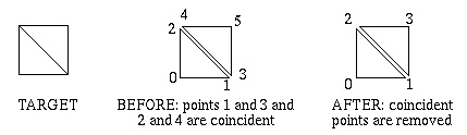
Programs designed to work with geometric modelers often receive geometry in a stream. This means they cannot ascertain the overall connectedness of a shell’s faces. For instance, to define a diagonally-split quadrilateral using two faces, one needs only four vertices, with two of them referenced twice. While it is geometrically correct to redefine the “re-used” vertices, for a total of six, face-connectivity information is lost. This is because duplicated points, though equivalent, are still distinct - each face has its “own” vertices. Compute_Optimized_Shell() recaptures the connectivity by eliminating the duplicated vertices and forcing faces to share the remaining unique vertices.
Faces that refer to fewer than three unique vertices are eliminated.
Since shells are arbitrary collections of faces, Compute_Optimized_Shell() can be used to convert a group of polygons into a coherent shell. The advantage is less data must be sent to HOOPS. Performance is improved since fewer points must be transformed and clipped.
Compute_Optimized_Shell() does not allocate memory for you. All arrays passed to it must contain adequate storage.
The following choices are recognized for options:
fix handedness
This option is a convenience for converting a minority of faces to the handedness comprising the majority.
Determines the handedness of the majority of faces, and reverses the winding of the minority faces. Returns facelist data to the caller. Shell data is modified in no other way. Mutually exclusive to options “fix handedness”, “skin”, and “lod”.
This option will also fix the special winding of holes (and nested holes) in shell faces also. A limitation of fixing face handedness is that we cannot do better than the “majority wins” method for the general case.
reverse handedness
This option is a convenience for reversing the winding of shell faces if the option “fix handedness” gives you an inside-out shell and you prefer not to change the appearance with the Heuristic “polygon handedness”.
Reverses the winding of each face in the facelist provided. Returns facelist data to the caller. Shell data is modified in no other way. Mutually exclusive to options “fix handedness”, “skin”, and “lod”.
It should not be necessary to pass in point data.
[no] [level of detail | lod] [ = xx% ]
Causes Compute_Optimized_Shell to abandon the normal redundant-vertices calculation in favor of calculating a Level of Detail (LOD). Any other choice will cause the shell to be reduced using shell simplification instead of the standard code path. The default reduction when LOD is turned on is 50%. If a percentage is specified in the form of xx%, the number of triangles in the model will be reduced to to the given percentage of the original model. The options “skin” and “lod” are mutually exclusive.
The new point count is guaranteed not to be larger than the original, so the original length can be used as upper bounds for allocation. The same goes for the facelist if the input is triangles. If quads (or polygons of higher order) are provided, then the output facelist may be larger. This is because our LOD algorithm outputs triangles only.
With quad input and level of detail = 100%, we will output double the faces. Triangle faces have 4/5 the number of integers that quad faces do, so we don’t need to double the facelist alloc size, rather multiply it by 1.6. This factor shrinks by user-provided level of detail. For example, with quad face input and level of detail = 75%, the new facelist alloc size becomes 1.6*0.75 = 1.2x original.
Generally, for turning n-gon data into a LOD shell with level of detail x, you are safe if you alloc an array of size (Original_FaceList_Length * 4*(n-2)/(n+1) * x).
Alternatively, you can safely run Optimize twice - first just to generate the facelist length (no array passed in), next with the array after your accurately sized alloc. This, however will take more cpu time.
Not set by default.
lod algorithm = [fast | nice]
Use the fast-LOD algorithm, with some visual quality degradation, or the “nice” LOD algorithm, with extra generation time but a better representation. Default is “fast”. Default is “fast”, but only applies if the “lod” option is used.
[no] orphan elimination
If this option is set, points that are not referenced by any face are removed. The default is “orphan elimination”.
[no] skin
Particularly geared towards the needs of the finite element analysis community, this option causes Compute_Optimized_Shell() to abandon its normal goal of merging nearby vertices in favor of extracting the exterior surface from shells that also have interior vertices and faces. This special computation mode works its magic by looking for pairs of faces that reference 3 or more of the same vertex indices. If coincident vertices are not shared for adjacent faces, this computation will not do anything (though running the standard form of Compute_Optimized_Shell() on the data first would solve that problem. The options, “skin” and “lod” are mutually exclusive. When “skin” mode is used only “orphan elimination” has any meaning - the rest are ignored. As usual, the new face list length and new point count are guaranteed not to be larger than the original, so the original lengths can be used as upper bounds for allocation. Not set by default.
[no] tolerance [= nnn oru / nnn % fru]
“Tolerance” controls the identification of duplicate points. If a specification is given in object-relative units (oru), then the points that are separated by a distance less than this value are considered equal.
Often, one cannot ascertain a “good” value for an object-relative tolerance. In this case, specify the tolerance using “feature-relative units (fru)”. Feature size is defined to be the smallest non-zero distance between any two adjacent vertices on any face. It is calculated internally by Compute_Optimized_Shell() , and is constant for the entire collection of faces. The feature-relative tolerance is expressed as a percentage of this minimum distance. A setting less than “tolerance = 100%
fru” guarantees that unequal vertices on a single face won’t be eliminated.
“No tolerance” is the same as “tolerance = 0 oru”.
The default is “no tolerance”.
[no] normal tolerance [= nnn deg / nnn rad / nnn]
“Normal Tolerance” also controls the identification of duplicate points. Points which have an angular difference greater than the specified normal tolerance are assumed to be unique.
“no normal tolerance” is the same as “normal tolerance = 0 deg”.
The default is “no normal tolerance”.
[no] collapsible [= <defined callbackname>]
This option enables the user to replace the default distance measure, euclidian distance, with their own function to determine whether any given two nearby points should be merged or not. While it was originally designed to accept normals as its primary information, any sort of pointer that is passed as normals in the call to Compute_Optimized_Shell will be passed through to the callback.
If you are not interested in the mapping lists, pass a null pointer for either the point_mapping_list or the face_mapping_list. If you are not interested in using normal information as a criterion for collapsing points, pass a null pointer for normals.
- NOTES
This function replaces Compute_Minimized_Shell() , which is now obsolete.
It is not legal to pass the same pointer for both input and output.
EXAMPLES
The following example demonstrates passing a struct pointer in place of normals.
typedef struct { // contents of this structure are unrestricted float myparam1, myparam2; } optimized_shell_passthru; // returns 1 if points a and b are collapsible - // 0 if points a and b are not collapsible int are_collapsible_callback ( void *pts_in, void *norms_in, int a, int b, double tolerance_squared, double normal_distance_squared ) { optimized_shell_passthru *info= (optimized_shell_passthru *) norms_in; // use info to do any test here, and return the result } // and this is how the function is called optimized_shell_passthru info = { a, b, etc. }; HC_Define_Callback_Name( "are_collapsible_callback", are_collapsible_callback ); HC_Compute_Optimized_Shell( in_point_count, in_points, (void *)(&info), in_face_list_length, in_face_list, "collapsible = are_collapsible_callback", &out_point_count, out_points, &out_face_list_length, out_face_list, vertex_mapping, face_mapping );
The following example demonstrates using the vertex_mapping array to copy attributes from the old shell to the new one. Two things to note from this example:
- a) that the check for “vertex_mapping >= 0” really is necessary, since unreferenced vertices from the original shell have vertex_mapping entries set to “-1”; and
- b) that performance could be improved if the normals from the original shell were available a priori in an array so that the vertices did not have to be individually opened.
- c) vertices in the new shell can potentially be touched more than once.
HC_Show_Shell( old_key, &point_count, points, &face_list_length, face_list ); HC_Compute_Optimized_Shell( &point_count, points, NULL, &face_list_length, face_list, "", &new_point_count, new_points, &new_face_list_length, new_face_list, vertex_mapping, face_mapping ); new_key = HC_Insert_Shell( new_point_count, new_points, new_face_list_length, new_face_list ); for( i = 0 ; i < point_count ; i++ ) { HC_Open_Geometry( old_key ); HC_Open_Vertex( i ); HC_Show_Normal( &x, &y, &z ); HC_Close_Vertex(); HC_Close_Geometry( ); if( vertex_mapping[i] >= 0 ) { HC_Open_Geometry( new_key ); HC_Open_Vertex( vertex_mapping[i] ); HC_Set_Normal( x, y, z ); HC_Close_Vertex(); HC_Close_Geometry( ); } }
See also
HC_Insert_Shell, HC_Show_Shell, HC_Show_Shell_Size.
Parameters: - pcount – Number of valid points in points.
- points – Vector of x-y-z triplets for the coordinates of the vertices that could be used to build the shell. (A simple N = 3 array can also be used.) Passed by reference always.
- normals – Sequential list of vertex normals, x-y-z triplets. It is legal to pass NULL for this parameter, in which case normal information will be ignored. If non-NULL, however, the normals are assumed to be normalized to length 1. Passed by reference always.
- flist_length – Total number of integers in face_list.
- face_list – Encoded description of how to connect the points to build the faces of the shell. Passed by reference always.
- options – A quoted string or a string variable containing a list of desired options. Passed by reference always.
- new_pcount – Number of valid points in new_points after computation. Returned to caller. Passed by reference always.
- new_points – Vector of x-y-z triplets for the coordinates of the non-redundant vertices that could be used to build the shell. (A simple N = 3 array can also be used.) Returned to caller. Passed by reference always.
- new_flist_length – Total number of integers in computed new_face_list. Returned to caller. Passed by reference always.
- new_face_list – Encoded description of how to connect the points to build the faces of the computed shell. Returned to caller. Passed by reference always.
- point_mapping_list – Mapping of vertices from the original point list to the vertices in the new (computed) point list. In other words, for each old vertex i, point_mapping_list[i] represents the vertex in the new shell to which it has moved. Eliminated points are mapped to -1. Returned to caller. Passed by reference always.
- face_mapping_list – Mapping of faces from the original face list to the new (computed) face list. In other words, for each old face j, face_mapping_list[j] represents the vertex in the new shell to which it has moved. Eliminated faces are mapped to -1. Returned to caller. Passed by reference always.
-
Key
HC_Compute_Capping_Shell(int shell_count, Key const shell_list[], float const plane[]) Creates a shell in the currently open segment that contains an exact copy of the cap geometry that a plane would make when applied to the provided shells.
This function allows developers to access the cap geometry that 3dGS creates when cutting planes are inserted into the scene and capping geometry is turned on. The capping geometry is returned as a single shell and is inserted into the currently open segment. Users must ensure that there is a valid open segment before calling this function.
- DETAILS
This function does not apply any modelling transforms to the supplied shells. Users must translate the shells into world space to ensure correct results. Also, the shell provided is a copy of the capping geometry and so the deletion and/or modification of the returned shell will not affect the caps in the scene.
- NOTES
This interface currently supports shell generation for cutting planes only. This function must operate on manifold shells. Non-manifold shells will not work.
- RESTRICTIONS
See also
HC_Insert_Shell, HC_Insert_Cutting_Plane, HC_Insert_Cutting_Section
Parameters: - shell_count – Number of shells in the shell list array.
- shell_list – List of shells for which the cap(s) will be generated.
- plane – An array of four floats that define the cap plane.
Returns: cap_key The key to the shell that will contain the capping geometry.
-
Key
HC_Compute_Boolean_Shell(int target_pcount, Point const target_points[], Vector const target_normals[], int target_flist_length, int const target_face_list[], int tool_pcount, Point const tool_points[], Vector const tool_normals[], int tool_flist_length, int const tool_face_list[], char const *options) Performs one of several boolean operations on two shells. IMPORTANT NOTE: This routine is primarily meant to provide a reasonable visual representation of the boolean result, and has limititions covered in the NOTES section which prevent this routine from being relied on to produce manifold shell results. The routine is provided AS-IS.
This function takes the definitions for two manifold shells and performs one of three boolean operations on those shells. The result is a new shell that gets inserted into the currently open segment. Valid choices for options* include the following:
- DETAILS
boolean type = [subtract | union | intersect]
Tells 3dGS which specific type of boolean operation to perform on the supplied shells. In the event of a union or an intersection, the order of target and tool does not matter. However, in the case of a subtraction the tool will be subtracted from the target shell.
plane coefficient = [float]
This value is used in the internal logic for determining the boolean result. Changing the value based on the scale of the object can give better results. For both the single and double precision version, the default setting is “plane coefficient = 0.000001”.
plane tolerance = [float]
This value is used in the internal logic for determining the boolean result. Changing the value based on the scale of the object can give better results. The default setting is “plane tolerance = 0.0003” for the single precision version. For the double precision version, the default setting is “plane tolerance = 0.000001”.
plane merge tolerance = [float]
This value is used in the internal logic for determining the boolean result. Changing the value based on the scale of the object can give better results. The default setting is “plane merge tolerance = 0.0003” for the single precision version. For the double precision version, the default setting is “plane merge tolerance = 0.000001”.
target handedness = [left|right]
The polygon handedness of the target shell. If not specified, “left” handedness is assumed.
tool handedness = [left|right]
The polygon handedness of the tool shell. If not specified, “left” handedness is assumed.
This function will perform a Compute_Optimized_Shell() on the resulting boolean shell data before placing it in the currently open segment. The shell will have left polygon handedness. The user may need to delete the tools and target in their scene depending on the intended behavior.
- RESTRICTIONS
The two shells that participate in the boolean operation must be closed and manifold bodies. There cannot be overlapping facets or other inconsistencies in the data. You must have consistent handedness in each input shell (though each shell can have it’s own handedness, e.g., the target can have right handedness and the tool can have left handedness) and you must specify the handedness in the options if it differs from the defaults, otherwise one can get unexpected results. The input shells must only contain convex faces.
The faces of the target and tool shells should not be co-planar.
The resulting shell of the Compute_Boolean_Shell() function may contain an excessive number of triangles in the region where the target and tool meet. If the boolean functionality is used for continuous surface removal (for example, recursive use of the boolean operation result as the input value for a subsequent boolean operation), this effect may become exacerbated.
- NOTES
Due to the nature of the algorithm, very small triangles may be produced which can lead to precision problems, such as missing faces or faces with wrong handedness. In extreme cases, these precision problems can lead to the creation of extraneous triangles.
See also
HC_Insert_Shell
Parameters: - target_pcount – Number of valid points in targetpoints.
- target_points – Vector of x-y-z triplets for the coordinates of the vertices that could be used to build the target shell. (A simple N = 3 array can also be used) Passed by reference always.
- target_normals – Sequential list of vertex normals of the target shell, x-y-z triplets. It is legal to pass NULL for this parameter, in which case normal information will be ignored. Passed by reference always.
- target_flist_length – Total number of integers in targetface_list
- target_face_list – Encoded description of how to connect the points to build the faces of the target shell. Passed by reference always.
- tool_pcount – Number of valid points in toolpoints.
- tool_points – Vector of x-y-z triplets for the coordinates of the vertices that could be used to build the tool shell. (A simple N = 3 array can also be used) Passed by reference always.
- tool_normals – Sequential list of vertex normals of the tool shell, x-y-z triplets. It is legal to pass NULL for this parameter, in which case normal information will be ignored. Passed by reference always.
- tool_flist_length – Total number of integers in toolface_list.
- tool_face_list – Encoded description of how to connect the points to build the faces of the tool shell. Passed by reference always.
- options – A quoted string or a string variable containing a list of desired options. Passed by reference always.
Returns: key
-
bool
HC_Compute_Polygon_Normal(int count, Point const points[], char const *hand, Vector *out_vector) See also
HC_Compute_Coordinates, HC_Compute_Polygon_Plane, HC_Compute_Transform, HC_Set_Modelling_Matrix, HC_Show_Polygon, HC_Show_Shell.
- DETAILS
- Compute_Polygon_Normal() accepts a list of points in the format of Insert_Polygon() and attempts to find a vector that is perpendicular to the polygon. If the points do not all lie in the same plane, the result is indeterminate. If no such vector can be found (the points are all co linear, for example), false is returned and out_vector is unchanged. The polygon must be defined as either “left-handed” (if the fingers of the left hand are curved around the points in the order defined, then the thumb will point in the direction of the normal) or as “right-handed”.
Parameters: - count – Number of xyz triplets in points
- points – As in Insert_Polygon() , xyz triplets to specify the 3D vertices of the polygon. Must be coplanar.
- hand – The definition order of the polygon “left” or “right”.
- out_vector – Output 3D vector returned to the caller.
Returns: success
-
bool
HC_DCompute_Polygon_Normal(int count, DPoint const points[], char const *hand, DVector *out_vector) Similar to Compute_Polygon_Normal, but operates on double-precision data.
Parameters: - count – Number of xyz triplets in points
- points – As in Insert_Polygon() , xyz triplets to specify the 3D vertices of the polygon. Must be coplanar.
- hand – The definition order of the polygon - “left” or “right”.
- out_vector – Output 3D vector returned to the caller.
Returns: success
-
bool
HC_Compute_Polygon_Plane(int count, Point const points[], char const *hand, Plane *out_plane) Compute_Polygon_Plane() is similar to Compute_Polygon_Normal() . The first three values are the polygon normal itself; the addition of the fourth value allows you to write the equation of the plane of the polygon in the form ax + by + cz* + d = 0. If no plane can be found, false is returned and out_plane is unchanged.
- DETAILS
See also
HC_Compute_Coordinates, HC_Compute_Polygon_Normal, HC_Compute_Transform, HC_Set_Modelling_Matrix, HC_Show_Device_Info, HC_Show_Polygon, HC_Show_Shell.
- NOTES
- If this function fails, it is often for the same reasons that Compute_Polygon_Normal would as well.
Parameters: - count – Number of xyz triplets in points
- points – As in Insert_Polygon() , xyz triplets to specify the 3D vertices of the polygon. Must be coplanar.
- hand – The definition order of the polygon - “left” or “right”.
- out_plane – Plane equation parameters (a,b,c,d ). Returned to the caller.
Returns: success
-
bool
HC_DCompute_Polygon_Plane(int count, DPoint const points[], char const *hand, DPlane *out_plane) Similar to Compute_Polygon_Plane, but operates on double-precision data.
Parameters: - count – Number of xyz triplets in points
- points – As in Insert_Polygon() , xyz triplets to specify the 3D vertices of the polygon. Must be coplanar.
- hand – The definition order of the polygon - “left” or “right”.
- out_plane – Plane equation parameters (a,b,c,d ). Returned to the caller.
Returns: success
-
void
HC_Compute_Rotation_Matrix(double alpha, double beta, double theta, float out_matrix[]) See also
HC_Set_Modelling_Matrix
- DETAILS
- Compute_Rotation_Matrix() produces a matrix representing a rotation about the origin. It consists of a rotation of alpha degrees about the X axis, of beta degrees about Y, and of theta degrees about Z.
Parameters: - alpha – Angle of rotation about the X axis.
- beta – Angle of rotation about the Y axis.
- theta – Angle of rotation about the Z axis.
- out_matrix – Output transformation matrix, returned to the caller.
-
void
HC_DCompute_Rotation_Matrix(double alpha, double beta, double theta, double out_matrix[]) Similar to Compute_Rotation_Matrix(), but operates on double-precision data.
Parameters: - alpha – Angle of rotation about the X axis.
- beta – Angle of rotation about the Y axis.
- theta – Angle of rotation about the Z axis.
- out_matrix – Output transformation matrix, returned to the caller.
-
void
HC_Compute_Scale_Matrix(double x, double y, double z, float out_matrix[]) See also
HC_Compute_Coordinates, HC_Set_Modelling_Matrix, HC_Show_Device_Info
- DETAILS
- Compute_Scale_Matrix() produces a matrix representing a uniform scaling of the scene. x, y, and z are the scalings along the *X, Y, and Z axes. These scale values are commonly positive and identical, but they do not need to be. Note, if any of (x, y, z) are zero, the matrix that results will be singular (non-invertible.)
Parameters: - x – Scale multiplier in the X direction.
- y – Scale multiplier in the Y direction.
- z – Scale multiplier in the Z direction.
- out_matrix – Output transformation matrix, returned to the caller.
-
void
HC_DCompute_Scale_Matrix(double x, double y, double z, double out_matrix[]) Similar to Compute_Scale_Matrix, but operates on double-precision data.
Parameters: - x – Scale multiplier in the X direction.
- y – Scale multiplier in the Y direction.
- z – Scale multiplier in the Z direction.
- out_matrix – Output transformation matrix, returned to the caller.
-
int
HC_Compute_Selection(char const *display, char const *start_seg, char const *action, double x, double y) Forces the explicit computation and generation of selection events.
Compute_Selection() allows access to the internal routines used for figuring selection events from mouse locations. Given the usual locater information, Compute_Selection() will observe the appropriate attributes and find out what lies at that position. If anything is found, a Selection Event is generated and is made the “current” event. Any previous current event is discarded. The various Show_Selection() routines can then be used to retrieve information about the selection.
- DETAILS
If a value for start_seg is given, then testing begins there. Coordinates are measured in terms of that segment’s effective window, and testing is restricted to that window.
The available values for actions are detailed in ::Set_Selectability(). You can also specify conditions for selections with the “conditions” option. For example, if you were viewing a model of a car, you could define a conditional attribute setting called “show_wheels” that makes all wheels in a scene visible, and activate it for only this selection using Compute_Selection(“?Picture”, “.”, “v, conditions = show_wheels”, 0, 0) .
Additionally, you can set driver options and heuristics which pertain to selection. These values will override the settings on the segment for this selection event. Currently this is the “selection proximity” driver option and the “selection level”, “visual selection”, “detail selection”, “selection sorting”, “related selection limit”, and “internal selection limit” which can be found in Set_Heuristics. See the documentation of Set_Driver_Options and Set_Heuristics for specific details on each of these options.
Compute_Selection_By_Area() lets you specify a rectangular region of the screen instead of a single point. Every item of geometry within or overlapping that region is identified and returned as part of the selection event. The “selection proximity” Driver Option is ignored in the case of testing “by area”, since the geometry must be properly within or overlapping the specified region. Everything within the area has equal status.
A typical programming sequence that computes a selection and does something with every one of the selected items follows (in pseudo-C):
if (Compute_Selection_By_Area (...) > 0) do { Show_Selection_Element (...) // ... process item... } while (Find_Related_Selection())
As with regular selection events, the “related” selections are returned in proximity order. If the proximities are zero (the position is within the item). The related sections are in front-to-back order. For “by area” selecting, the ordering is from the approximate center of the area.
Compute_Selection_By_Volume() lets you specify a volume of the screen. The meaning of “screen Z” coordinates is described in detail under Show_Selection_Position() . Hither must be less than or equal to yon. If display is given as blank or null, an “object space” test is done, as described below. Similar to Compute_Selection_By_Area() , Compute_Selection_By_Polylin() lets you specify a polyline. Any object intersected by the path of the polyline is selected. Selection by polyline will allow users to select things that are outside of the view frustum, as long as analytic selection is used. The points that define the polyline have their X and Y values defined in window coordinates. The Z values are ignored.
Compute_Selection_By_Polygon() lets you specify a polygon instead of a polyline. Every item of geometry, within or overlapping the region defined by the polygon, is identified and returned as part of the selection event. Selecting using a polygon will select anything that intersects it, even if the geometry is off the screen. The points that define the polygon have their X and Y values defined in window coordinates. The Z values are ignored.
Compute_Selection_By_Volume() does its selection in “object space”. The idea of an object-space test is to search a certain volume of space without reference to any screen display. In particular:
- Only Compute_Selection_By_Volume() and Compute_Selection_By_Shell() permit this mode.
- All input values (left, right, point etc.) must be in terms of start_seg’s coordinate system - the coordinate system used for defining geometry within start_seg.
- Returned values (see Show_Selection_Position() ) will be in that coordinate system. Windowed inner segments in start_seg are skipped over.
- Cameras attached to inner segments are warned about (unless they are skipped because of the “windowed inner segment” rule).
- The hidden-surface front-to-back ordering is not meaningful. Items are returned (see Show_Selection() and Find_Related_Selection() ) in the order they are encountered in the database.
- Inner modelling matrices are respected. The values returned by Show_Selection_Position() remain in terms of start_seg’s coordinate system.
The status returned by Show_Selection_Source() will be a one if action was “v” or “*”, otherwise zero.
- NOTES
Selectability and visibility are enforced during a Compute_Selection() just as they are during normal user input. An object must be both visible and selectable to be selected. The “attribute lock” rendering option might be useful for overriding these.
In the current implementation, display, if given, has to be a real driver segment. There are, however, ways to get around this. Selecting works if the window visibility for display itself is turned off. Alternatively, a debugging driver - “?driverprintf/null” - can be used for display (the “?driver/null” driver cannot do selection testing.) If you do use “printf/null”, the “physical size” Driver Option might be useful to get the nominal shape of the screen right.
In the current implementation, if a blank or null start_seg is given to Compute_Selection_By_Area() (so that window-selecting is turned on), then at most one window selected - the window in effect for the center of the area. Geometry testing will be limited to that one window.
In the current implementation, the selection-testing code can include a geometry item even if the item is completely covered up by a polygon closer to the camera. For example - if the item doesn’t know how to tell that the geometry is actually invisible. (Note the closer polygon will be returned first.) Likewise, once the testing code decides the action is within a particular window it becomes oblivious to extraneous windows that may overlap some of the geometry.
Compute_Selection() always makes its result the “current” event. To take advantage of having a queue of events, you could use Queue_Location_Event() to save the information. Then do Compute_Selection() when you see the Location event coming off the queue.
Compute_Selection_By_Area() typically requires first letting the user rubberband a bounding box into position. The bounding box is conveniently done in a subsegment that has a viewing camera such as
Set_Camera_By_Volume ("stretched", -1., 1., -1., 1.)
This makes the geometry coordinate system the same as the window coordinate system. (The “quick moves” heuristic can also be useful for rubberbanding.)
Once you have called Compute_Selection(), you can iterate through the list of selected objects via Find_Related_Selection(). Note that the returned selected objects are sorted by z-order for direct hits (objects that were directly under the selection ray calculated from the position camera and the hit point) followed by objects that were not in the path of the ray but were within the “selection proximity” of the ray and that these are sorted by their proximity to the ray.
See also
HC_Begin_Shell_Selection, HC_Compute_Coordinates, HC_Find_Related_Selection, HC_Set_Selectability, HC_Set_Visibility, HC_Set_Driver_Options, HC_Show_Selection_Pathname, HC_Set_Heuristics.
- RESTRICTIONS
- The start_seg parameter must not be an included segment.
Parameters: - display – Commonly “?Picture”. In general, a segment with an attached device driver that knows how to test for selections.
- start_seg – A segment somewhere in the tree belonging to display, at which point it would be good to start selection testing. If blank or null, then testing begins at display.
- action – One of “v”, “^”, “*”, or “O”, as well as “conditions”, i.e., *”v, conditions=my_condition”*. Action is compared against the Selectability attribute settings as testing proceeds. See details for a discussion on actions.
- x – The nominal mouse x-position, measured in window coordinates: -1.0 to +1.0. If start-seg is non-blank, then the parameter is taken in terms of the window in effect on start-seg, otherwise in terms of display.
- y – The nominal mouse y-position
Returns: count
-
int
HC_Compute_Selection_By_Area(char const *display, char const *start_seg, char const *action, double left, double right, double bottom, double top) Similar to Compute_Selection(), but operates on a rectangular area.
See also
HC_Compute_Selection()
- RESTRICTIONS
- The start_seg parameter must not be an included segment.
Parameters: - display – Commonly “?Picture”. In general, a segment with an attached device driver that knows how to test for selections.
- start_seg – A segment somewhere in the tree belonging to display, at which point it would be good to start selection testing. If blank or null, then testing begins at display.
- action – One of “v”, “^”, “*”, or “O”, as well as “conditions”, i.e., *”v, conditions=my_condition”*. Action is compared against the Selectability attribute settings as testing proceeds. See Set_Selectability() for a detailed explanation of actions.
- left – The -(x) boundary for a rectangular area of the screen, in window coordinates
- right – The (x) boundary for a rectangular area of the screen, in window coordinates
- bottom – The -(y) boundary for a rectangular area of the screen, in window coordinates
- top – The (y) boundary for a rectangular area of the screen, in window coordinates
Returns: count
-
int
HC_Compute_Selection_By_Polygon(char const *display, char const *start_seg, char const *action, int pcount, Point const points[]) Similar to Compute_Selection(), but operates on a polygonal area.
- RESTRICTIONS The start_seg parameter must not be an included segment. \sa HC_Compute_Selection()
Parameters: - display – Commonly “?Picture”. In general, a segment with an attached device driver that knows how to test for selections.
- start_seg – A segment somewhere in the tree belonging to display, at which point it would be good to start selection testing. If blank or null, then testing begins at display.
- action – One of “v”, “^”, “*”, or “O”, as well as “conditions”, i.e., “v, conditions=my_condition”. Action is compared against the Selectability attribute settings as testing proceeds. See Set_Selectability() for a detailed explanation of actions.
- pcount – Number of points contained in the points list.
- points – Set of points that comprise the polyline or polygon used to compute the selection.
Returns: count
-
int
HC_Compute_Selection_By_Polylin(char const *display, char const *start_seg, char const *action, int pcount, Point const points[]) Similar to Compute_Selection(), but operates on polyline intersections.
- RESTRICTIONS The start_seg parameter must not be an included segment. \sa HC_Compute_Selection()
Parameters: - display – Commonly “?Picture”. In general, a segment with an attached device driver that knows how to test for selections.
- start_seg – A segment somewhere in the tree belonging to display, at which point it would be good to start selection testing. If blank or null, then testing begins at display.
- action – One of “v”, “^”, “*”, or “O”, as well as “conditions”, i.e., *”v, conditions=my_condition”*. Action is compared against the Selectability attribute settings as testing proceeds. See Set_Selectability() for a detailed explanation of actions.
- pcount – Number of points contained in the points list.
- points – Set of points that comprise the polyline or polygon used to compute the selection.
Returns: count
-
int
HC_Compute_Selection_By_Volume(char const *display, char const *start_seg, char const *action, double left, double right, double bottom, double top, double hither, double yon) Similar to Compute_Selection(), but operates on a cuboid volume.
See also
HC_Compute_Selection()
Parameters: - display – Commonly “?Picture”. In general, a segment with an attached device driver that knows how to test for selections. If blank or null, then an “object space selection” is made.
- start_seg – A segment somewhere in the tree belonging to display, at which point it would be good to start selection testing. If blank or null, then testing begins at display.
- action – One of “v”, “^”, “*”, or “O”, as well as “conditions”, i.e., *”v, conditions=my_condition”*. Action is compared against the Selectability attribute settings as testing proceeds. See Set_Selectability() for a detailed explanation of actions.
- left – The -(x) boundary for a rectangular area of the screen, in window coordinates
- right – The (x) boundary for a rectangular area of the screen, in window coordinates
- bottom – The -(y) boundary for a rectangular area of the screen, in window coordinates
- top – The (y) boundary for a rectangular area of the screen, in window coordinates
- hither – The -(z) boundary, described in Show_Selection_Position() .
- yon – The (z) boundary, described in Show_Selection_Position() .
Returns: found
-
void
HC_Compute_Text16_From_Text(char const *intext, char const *encoding, int *outcount, unsigned short outtext16[]) Converts from integer-array representations of 16-bit characters to string representations.
See also
HC_Compute_Text_From_Text16()
Parameters: - intext – The characters in packed-byte format.
- encoding – Any of the encoding constants described under Insert_Text() .
- outcount – The number of characters unpacked into outtext16. Passed by reference always. Returned to user.
- outtext16 – The characters in full 16-bit format, one per short element after unpacking. Passed by reference always. Returned to user.
-
bool
HC_Compute_Text_Extent(char const *segment, char const *text, float *xsize, float *ysize) Finds out what the dimensions are for a given text string.
Unlike most geometry, the size of text depends on a complicated concatenation of attributes, and figuring it out from first principles is not straightforward. Compute_Text_Extent() performs the calculation for you. The returned value for xsize and ysize will be a fraction from 0.0 to 1.0 (or more) of the segment’s window.
- DETAILS
Once you have the text extent, it can be used, for example, to build a small bounding box around text that’s being used for string input (to limit the scope of screen updates). Or to lay out a popup menu big enough for the contained text. Or to wrap a highlight line around text.
If you use the text extent numbers to lay out windows, you usually need to multiply xfrac and yfrac by two to convert to a window distance, since windows range from -1 to +1. For example, to build a subwindow at the lower-left of the currently-open segment that’s just big enough to hold a “rabbit”, you might do the following:
Compute_Text_Extent (".", "rabbit", &xfrac, &yfrac) Open_Segment ("") Set_Window (-1., -1. + 2*xfrac, -1., -1. + 2*yfrac) Insert_Text (0., 0., 0., "rabbit") Close_Segment ()
For text with the transforms option enabled via Set_Text_Font(), the xsize and ysize values will be returned in object relative units (oru) instead of the usual screen relative units.
In versions prior to 16.0, the extent returned included a small amount of white space all around. Now, the default behavior for Compute_Text_Extent returns the exact extent for the specified text. To revert to the behavior displayed by Compute_Text_Extent prior to 16.0, you can turn on the legacy text extent option in #Define_System_Options.
- NOTES
This compute function does not include descenders or ascenders, such as accents over capitals letters, in the extent calculations.
The device will be “started” if necessary for the Info routines to work. See Show_Font_Info() for details.
Any reference in your program to Compute_Text_Extent_With_Enc() will cause the Kanji font data to be linked. This may increase the size of your executable image.
Compute_Text_Extent_With_Enc() looks odd because it’s been truncated at 31 characters.
The Compute_XXX() routines that require information about display drivers, do not work if they are called from an included segment. This specifically includes Compute_Text_XXX() routines. Display information must be associated with a window to return information about the display.
- RESTRICTIONS
Calling Compute_XXX() routines to obtain data associated with a display generates an update. On most devices, this poses no problem. However, for hardcopy devices such as Postscript or CGM, this can generate a blank page. To avoid this problem, applications often open a temporary driver subsegment. The application calls the compute routine, retains the computed information, and then discards the temporary driver subsegment.
See also
HC_PShow_Net_Text_Font, HC_PShow_Net_Text_Path, HC_PShow_Net_Text_Alignment, HC_Show_Device_Info, HC_Show_Font_Info, HC_Show_Text, HC_Show_Text_Encoding, HC_Compute_Coordinates, HC_Compute_Transform
Parameters: - segment – The segment whose attributes (or net attributes) will be applied to the problem.
- text – The text string whose extent is to be tested.
- xsize – The size of the text in the X direction. Returned to the user. Passed by reference always.
- ysize – The size of the text in the Y direction. Returned to user. Passed by reference always.
-
bool
HC_Compute_Text_Extent_By_Key(Key key, float *xfrac, float *yfrac) Similar to Compute_Text_Extent(), but operates on text referenced by an HC_KEY.
See also
HC_Compute_Text_Extent()
Parameters: - key – Key of the text on which the computation is to be done.
- xfrac – The fraction from 0.0 to 1.0 (or more), in the X direction, of segment’s window that is necessary to hold text. Returned to user. Passed by reference always.
- yfrac – The fraction from 0.0 to 1.0 (or more), in the Y direction, of segment’s window that is necessary to hold text. Returned to user. Passed by reference always.
-
bool
HC_Compute_Text_Extent_By_Path(int count, Key const keys[], char const *text, float *xfrac, float *yfrac) Similar to Compute_Text_Extent(), but concatenates the matrices along a segment path rather than the currently open segment.
See also
HC_Compute_Text_Extent()
Parameters: - count – The size of the keys array
- keys –
The array of keys starting with the owning segment and following
all the way back to the root segment or other desired segment.
- text – The text string whose extent is to be tested.
- xfrac – The fraction from 0.0 to 1.0 (or more), in the X direction, of segment’s window that is necessary to hold text. Returned to user. Passed by reference always.
- yfrac – The fraction from 0.0 to 1.0 (or more), in the Y direction, of segment’s window that is necessary to hold text. Returned to user. Passed by reference always.
-
bool
HC_Compute_Text_Extent_Enc_Path(int count, Key const keys[], char const *encoding, void const *text, float *xfrac, float *yfrac) Similar to Compute_Text_Extent_By_Path(), but operates on encoded text rather that Latin1 text.
See also
HC_Compute_Text_Extent()
Parameters: - count – The size of the keys array
- keys –
The array of keys starting with the owning segment and following
all the way back to the root segment or other desired segment.
- encoding – The encoding method used for text.
- text – The text string whose extent is to be tested.
- xfrac – The fraction from 0.0 to 1.0 (or more), in the X direction, of segment’s window that is necessary to hold text. Returned to user. Passed by reference always.
- yfrac – The fraction from 0.0 to 1.0 (or more), in the Y direction, of segment’s window that is necessary to hold text. Returned to user. Passed by reference always.
-
bool
HC_Compute_Text_Extent_With_Enc(char const *segment, char const *encoding, void const *text, float *xfrac, float *yfrac) Similar to Compute_Text_Extent() but operates on encoded text rather than Latin1 text.
See also
HC_Compute_Text_Extent()
Parameters: - segment – The segment whose attributes (or net attributes) will be applied to the problem.
- encoding – The encoding method used for text.
- text – The text string whose extent is to be tested.
- xfrac – The fraction from 0.0 to 1.0 (or more), in the X direction, of segment’s window that is necessary to hold text. Returned to user. Passed by reference always.
- yfrac – The fraction from 0.0 to 1.0 (or more), in the Y direction, of segment’s window that is necessary to hold text. Returned to user. Passed by reference always.
-
bool
HC_Compute_Text_Metrics(int count, Key const *keys, char const *encoding, void const *text, char const *options, int *size, float values[])
-
bool
HC_Compute_Text_Metrics_Size(int count, Key const *keys, char const *encoding, void const *text, char const *options, int *size)
-
void
HC_Compute_Text_From_Text16(int incount, unsigned short const intext16[], char const *encoding, char *outtext) Converts from string to integer-array representations of 16-bit characters.
HOOPS routines such as Insert_Text_With_Encoding() and Show_String_With_Encoding() expect their input and output to be in a “packed byte” format described under Insert_Text() . It’s more convenient, however, for your program to do its text work with the text packed exactly one character per 16-bit word. Compute_Text_From_Text16() and Compute_Text16_From_Text() make this conversion for you.
- DETAILS
The Compute_XXX() routines that require information about display drivers, do not work if they are called from an included segment. Display information must be associated with a window to return information about the display.
- RESTRICTIONS
Calling Compute_XXX() routines to obtain data associated with a display generates an update. On most devices, this poses no problem. However, for hardcopy devices such as Postscript or CGM, this can generate a blank page. To avoid this problem, applications often open a temporary driver subsegment, call the compute routine, retain the computed information, and then discard the temporary driver subsegment.
See also
HC_Insert_Text, HC_Edit_Text, HC_Show_Text, HC_Show_Text_Encoding, HC_Get_String, HC_Show_String.
Parameters: - incount – Number of characters in intext16.
- intext16 – An array of 16-bit integers. Each integer represents one short character.
- encoding – Any of the encoding constants described under Insert_Text() .
- outtext – The characters from “intext16”, in packed byte format. Passed by reference always. Returned to user.
-
void
HC_Compute_Text_Outline(char const *segment, char const *text, int *pcount, Point points[], int *flist_length, int face_list[]) Calculates a polyhedral representation of the given text glyphs.
Often, setting the path or alignment of text isn’t enough to acheive certain effects. For example, one might want to “warp” text characters or render them under the influence of light sources or a texture map. In these instances, normal Hoops text is not flexible enough, but other Hoops geometries are. Compute_Text_Outline() is the gateway between text characters and their geometric representations.
- DETAILS
The output of these routines is exactly like Show_Shell() and its variants. The data collected from Compute_Text_Outline() can be passed directly to Insert_Shell() . Shells can be subjected to a wide range of transformations and renderings.
You can use Compute_Text_Outline_Size() to determine how large the points and face_list arrays are going to need to be, before you actually call Compute_Text_Outline() .
The text attributes in effect within the segment are taken into account when generating the outline, obeying the typeface selection, size, etc.
The points that are returned will all lie in the z=0 plane, and will be scaled down by the text size so that the glyphs will nominally be of unit height, with protruding ascenders and descenders. Even if the text has already been inserted at some position in a segment, the resulting points will be returned with (0,0,0) as the first character’s origin. Since the geometric representation has the same physical dimensions, no matter which text size is chosen, text size may be used to control the resolution of the generated outline. Increasing the text size gives you more points, not a larger figure.
See also
HC_Insert_Text, HC_Show_Font_Info, HC_PShow_Net_Text_Font, HC_PShow_Net_Text_Path, HC_PShow_Net_Text_Alignment, HC_Show_Device_Info, HC_Show_Font_Info, HC_Show_Text, HC_Show_Text_Encoding, HC_Compute_Coordinates, HC_Compute_Text_Extent, HC_Compute_Transform
- NOTES
- Some of the routine names look odd because they’ve been truncated at 31 characters.
- RESTRICTIONS
- Not all text fonts have outline representations. If you request an outline from a text font and one cannot be generated, a warning message is issued. You should use Show_Font_Info() to determine if a font is “outlineable”.
Parameters: - segment – The segment whose attributes (or net attributes) will be applied to the problem.
- text – The text string whose outline is to be computed.
- pcount – Number of valid points in points. Returned to caller. Passed by reference always.
- points – Vector of x-y-z triplets for the coordinates of the vertices to be used to build the outline. (A simple N x 3 array may also be used.) Returned to caller. Passed by reference always.
- flist_length – Total number of integers in face_list. Returned to caller. Passed by reference always.
- face_list – Encoded description of how to connect the points to build the faces of the outline. Returned to caller. Passed by reference always.
-
void
HC_Compute_Text_Outline_By_Key(Key key, int *pcount, Point points[], int *flist_length, int face_list[]) Similar to Compute_Text_Outline(), but operates on an object referenced by an HC_KEY.
See also
HC_Compute_Text_Outline()
Parameters: - key – The numeric identifier returned by a previous call to Insert_Text() or Insert_Text_With_Encoding() .
- pcount – Number of valid points in points. Returned to caller. Passed by reference always.
- points – Vector of x-y-z triplets for the coordinates of the vertices to be used to build the outline. (A simple N x 3 array may also be used.) Returned to caller. Passed by reference always.
- flist_length – Total number of integers in face_list. Returned to caller. Passed by reference always.
- face_list – Encoded description of how to connect the points to build the faces of the outline. Returned to caller. Passed by reference always.
-
void
HC_Compute_Text_Outline_Size(char const *segment, char const *text, int *pcount, int *flist_length) Finds out the size of the text outline. This is useful for determining the size of the points array needed to store incoming data from Compute_Text_Outline().
See also
HC_Compute_Text_Outline()
Parameters: - segment – The segment whose attributes (or net attributes) will be applied to the problem.
- text – The text string whose outline is to be computed.
- pcount – Number of valid points in points. Returned to caller. Passed by reference always.
- flist_length – Total number of integers in face_list. Returned to caller. Passed by reference always.
-
void
HC_Compute_Text_Outline_Size_By(Key key, int *pcount, int *flist_length) Similar to Compute_Text_Outline_Size(), but enables the user to pass in a key for the desired text object.
See also
HC_Compute_Text_Outline()
Parameters: - key – The numeric identifier returned by a previous call to Insert_Text() or Insert_Text_With_Encoding() .
- pcount – Number of valid points in points. Returned to caller. Passed by reference always.
- flist_length – Total number of integers in face_list. Returned to caller. Passed by reference always.
-
void
HC_Compute_Text_Outline_Size_Wi(char const *segment, char const *encoding, void const *etext, int *pcount, int *flist_length) Similar to Compute_Text_Outline_Size(), but operates on encoded text rather than Latin1 text.
See also
HC_Compute_Text_Outline()
Parameters: - segment – The segment whose attributes (or net attributes) will be applied to the problem.
- encoding – The encoding method used for text.
- etext – Same as text, but encoded as in Insert_Text_With_Encoding() .
- pcount – Number of valid points in points. Returned to caller. Passed by reference always.
- flist_length – Total number of integers in face_list. Returned to caller. Passed by reference always.
-
void
HC_Compute_Text_Outline_With_En(char const *segment, char const *encoding, void const *etext, int *pcount, Point points[], int *flist_length, int face_list[]) Similar to Compute_Text_Outline(), but operates on encoded text rather than Latin1 text.
See also
HC_Compute_Text_Outline()
Parameters: - segment – The segment whose attributes (or net attributes) will be applied to the problem.
- encoding – The encoding method used for text.
- etext – Same as text, but encoded as in Insert_Text_With_Encoding() .
- pcount – Number of valid points in points. Returned to caller. Passed by reference always.
- points – Vector of x-y-z triplets for the coordinates of the vertices to be used to build the outline. (A simple N x 3 array may also be used.) Returned to caller. Passed by reference always.
- flist_length – Total number of integers in face_list. Returned to caller. Passed by reference always.
- face_list – Encoded description of how to connect the points to build the faces of the outline. Returned to caller. Passed by reference always.
-
void
HC_Compute_Text_Outline_By_Path(int count, Key const keys[], char const *text, int *pcount, Point points[], int *flist_length, int face_list[]) Similar to Compute_Text_Outline(), but concatenates the matrices along a segment path rather than the specified segment.
See also
HC_Compute_Text_Outline().
Parameters: - count – - The size of the keys array
- keys – - The array of keys starting with the text key (or effective owning segment if a text string is explicitly specified) and following all the way back to the root segment or other desired segment.
- text – - The text string whose outline is to be computed. ignored if first key in path is a text key.
- pcount – - Number of valid points in points. Returned to caller. Passed by reference always.
- points – Vector of x-y-z triplets for the coordinates of the vertices to be used to build the outline. (A simple N x 3 array may also be used.) Returned to caller. Passed by reference always.
- flist_length – - Total number of integers in face_list. Returned to caller. Passed by reference always.
- face_list – - Encoded description of how to connect the points to build the faces of the outline. Returned to caller. Passed by reference always.
-
void
HC_Compute_Text_Outline_Size_Pa(int count, Key const keys[], char const *text, int *pcount, int *flist_length) Similar to Compute_Text_Outline(), but concatenates the matrices along a segment path rather than the specified segment.
See also
HC_Compute_Text_Outline().
Parameters: - count – - The size of the keys array
- keys – - The array of keys starting with the text key (or effective owning segment if a text string is explicitly specified) and following all the way back to the root segment or other desired segment.
- text – - The text string whose outline is to be computed. ignored if first key in path is a text key.
- pcount – - Number of valid points in points. Returned to caller. Passed by reference always.
- flist_length – - Total number of integers in face_list. Returned to caller. Passed by reference always.
-
bool
HC_Compute_Transform(char const *segment, char const *in_system, char const *out_system, float matrix[]) Converts positions back and forth among the various coordinate systems.
This routine examines the attributes present on segment and its owners, returns a matrix suitable for converting points or planes from in_system coordinates to out_system coordinates. The matrix will often be passed directly to Compute_Transformed_Points() or Compute_Transformed_Plane() .
- DETAILS
If you have just one or a couple of points to transform it might be more efficient to call Compute_Coordinates() , the sister routine of Compute_Transform() . Also, if you are going to call Compute_Transformed_Plane() for a number of planes, check the note on efficiency at the bottom of Compute_(Vectors_and_Matrices).
The in_system and out_system parameters to Compute_Coordinates() is a comma-separated list of options which can include the following:
local window
The value is in terms of the local window for segment. (The Z coordinate is usually zero.)
outer window
The value is in terms of the outermost window for segment. (“Outermost” refers to the first segment going up from segment which has a Driver attribute.)
local pixels
The value is measured in screen pixels within the local window on segment. The upper-left of the window is pixel (0, 0); they descend going down and to the right. (The Z coordinate is usually zero.)
outer pixels
The value is in terms of pixels within the outermost window on segment.
viewpoint
The value is in viewpoint coordinate system, which is based on the position of the observer (camera). The origin is at the camera position. The viewing direction is the Z axis and the camera up vector is the Y axis.
world
The value is in normal world coordinates (the coordinate system in which the camera is positioned; the coordinates of geometry after modelling matrices have been applied, but before projecting through a camera into a window.) A window Z value of zero maps to the current camera “target” plane.
camera
The coordinate system used in calls to Set_Camera_Position() , etc. A synonym for world coordinates.
object
The value is in the coordinate system that real geometry lives in (such as “world” coordinates, but does not include the Modelling Matrices, if any).
If a conversion is ambiguous (one of the matrices is singular), the system chooses arbitrarily among the valid possibilities. If a conversion is impossible (e.g., the camera is singular), a false function status returns and matrix will be unchanged.
If your transform doesn’t include a perspective transform - if it doesn’t include going from world or camera space to a perspective window space - the fourth column of the returned matrix is guaranteed to be zero-zero-zero-one.
- NOTES
If the fourth column of a matrix is not zero-zero-zero-nonzero, that matrix can’t be used in a call to Set or Append Modelling Matrix.
If the in_system specification matches the out_system specification, the routine immediately returns true with an identity matrix. In the interest of speed, no error checking is conducted.
Calling Compute_XXX() routines to obtain data associated with a display generates an update. On most devices, this poses no problem. However, for hardcopy devices such as Postscript or CGM, this can generate a blank page. To avoid this problem, applications often open a temporary driver subsegment, call the compute routine, retain the computed information, and then discard the temporary driver subsegment.
- RESTRICTIONS
- The Compute_XXX() routines that require information about display drivers, do not work if they are called from an included segment. Display information must be associated with a window to return information about the display.
See also
HC_Compute_Coordinates, HC_Show_Selection_Position, HC_Show_Polyline, HC_Show_Shell, HC_Show_Marker.
Parameters: - segment – The name of a segment that provides the Window, Camera, and/or Driver attributes for the conversion.
- in_system – Special constants for the input and output coordinate spaces.
- out_system – Special constants for the input and output coordinate spaces.
- matrix – The transformation matrix necessary to take points from in_system to out_system. Passed by reference in all languages. May need to be transposed in languages other than C (unless immediately passed back into Visualize.) Returned to user.
Returns: success
-
bool
HC_DCompute_Transform(char const *segment, char const *in_system, char const *out_system, double matrix[]) Similar to Compute_Transform(), but operates on double-precision data.
Parameters: - segment – The name of a segment that provides the Window, Camera, and/or Driver attributes for the conversion.
- in_system – Special constants for the input and output coordinate spaces.
- out_system – Special constants for the input and output coordinate spaces.
- matrix – The transformation matrix necessary to take points from in_system to out_system. Passed by reference in all languages. May need to be transposed in languages other than C (unless immediately passed back into Visualize.) Returned to user.
Returns: success
-
bool
HC_Compute_Transform_By_Path(int count, Key const keys[], char const *in_system, char const *out_system, float matrix[]) Similar to Compute_Transform(), but concatenates the matrices along a segment path rather than the currently open segment.
See also
HC_Compute_Transform()
Parameters: - count – The size of the keys array
- keys – The array of keys starting with the owning segment and following all the way back to the root segment or other desired segment.
- in_system – Special constants for the input and output coordinate spaces.
- out_system – Special constants for the input and output coordinate spaces.
- matrix –
- The transformation matrix necessary to take points from in_system to out_system. Passed by reference in all languages. May need to be transposed in languages other than C (unless immediately passed back into HOOPS.) Returned to user.
Returns: success
-
bool
HC_DCompute_Transform_By_Path(int count, Key const keys[], char const *in_system, char const *out_system, double matrix[]) Similar to Compute_Transform_By_Path(), but operates on double-precision data.
See also
HC_Compute_Transform_By_Path()
Parameters: - count – The size of the keys array
- keys – The array of keys starting with the owning segment and following all the way back to the root segment or other desired segment.
- in_system – Special constants for the input and output coordinate spaces.
- out_system – Special constants for the input and output coordinate spaces.
- matrix – The transformation matrix necessary to take points from in_system to out_system. Passed by reference in all languages. May need to be transposed in languages other than C (unless immediately passed back into HOOPS.) Returned to user.
Returns: success
-
bool
HC_Compute_Transformed_Plane(Plane const *plane, float const matrix[], Plane *out_plane) Applies a user-defined transform to a single plane.
Since by nature a plane transform involves a (expensive) matrix adjoint calculation, it is important for performance reasons to use the Compute_Transformed_Planes() variant whenever you have a large number of planes that need to be transformed by the same matrix.
- DETAILS
- Compute_Transformed_Plane() accepts a general 4x4 matrix, inverts it, multiplies it on the right by the plane equation, and normalizes the result. This action produces a new plane equation. The first three values of the transformed plane represent the transformed normal vector. If the matrix or the transformed plane is singular, false is returned and out_plane is unchanged. If you have many planes to convert it might be more efficient to invert the matrix (or, better, to find the adjoint) once, then multiply the planes through it by hand.
- NOTES
See also
HC_Compute_Coordinates, HC_Compute_Polygon_Plane, HC_Compute_Transform, HC_Set_Modelling_Matrix, HC_Show_Device_Info, HC_Show_Geometry_Pointer, HC_Show_Polygon, HC_Show_Shell.
Parameters: - plane – Input plane equation parameters (a,b,c,d).
- matrix – Input transformation matrix.
- out_plane – Plane equation parameters (a,b,c,d ). Returned to caller. Can point to the same place as plane.
Returns: True if the calculation was a success
-
bool
HC_DCompute_Transformed_Plane(DPlane const *plane, double const matrix[], DPlane *out_plane) Similar to Compute_Transformed_Plane(), but operates on double-precision data.
Parameters: - plane – Input plane equation parameters (a, b, c, d).
- matrix – Input transformation matrix.
- out_plane – Plane equation parameters (a, b, c, d). Returned to caller. Can point to the same place as plane.
Returns: True if the calculation was a success
-
bool
HC_Compute_Transformed_Planes(int count, Plane const planes[], float const matrix[], Plane out_planes[]) Applies a user-defined transform to a group of planes.
See also
HC_Compute_Transformed_Plane()
Parameters: - count – Number of plane equations in planes
- planes – A 4 x count array of plane equation parameters (a, b, c, d).
- matrix – Input transformation matrix.
- out_planes – Plane equation parameters (a, b, c, d). Returned to planes the caller. Can point to the same place as plane.
Returns: True if the calculation was a success
-
bool
HC_DCompute_Transformed_Planes(int count, DPlane const planes[], double const matrix[], DPlane out_planes[]) Applies a user-defined transform to a group of planes.
See also
HC_Compute_Transformed_Plane()
Parameters: - count – Number of plane equations in planes
- planes – A 4 x count array of plane equation parameters (a,b,c,d).
- matrix – Input transformation matrix.
- out_planes – Plane equation parameters (a, b, c, d). Returned to planes the caller. Can point to the same place as plane.
Returns: True if the calculation was a success
-
void
HC_Compute_Transformed_Points(int count, Point const points[], float const matrix[], Point out_points[]) Applies a user-specified transform to any number of points.
See also
HC_Compute_Coordinates, HC_Compute_Transform, HC_Set_Modelling_Matrix, HC_Show_Device_Info, HC_Show_Polyline, HC_Show_Shell, HC_Show_Marker.
Parameters: - count – Number of xyz triplets in points
- points – As in Insert_Polygon() , xyz triplets to specify the 3D vertices of the polygon.
- matrix – Input transformation matrix.
- out_points – Output points: points put through matrix. Can point to the same place as points.
-
void
HC_Compute_Translation_Matrix(double x, double y, double z, float out_matrix[]) See also
HC_Compute_Coordinates, HC_Set_Modelling_Matrix, HC_Show_Device_Info
Parameters: - x – Translation in the X direction.
- y – Translation in the Y direction.
- z – Translation in the Z direction.
- out_matrix – Output transformation matrix, returned to the caller.
-
void
HC_DCompute_Translation_Matrix(double x, double y, double z, double out_matrix[]) Similar to Compute_Translation_Matrix(), but operates on double-precision data.
Parameters: - x – Translation in the X direction.
- y – Translation in the Y direction.
- z – Translation in the Z direction.
- out_matrix – Output transformation matrix, returned to the caller.
-
double
HC_Compute_Vector_Length(Vector const *vector) See also
HC_Compute_Coordinates, HC_Compute_Cross_Product, HC_Compute_Dot_Product
Parameters: vector – Input 3D vector Returns: value the scalar length of a vector
-
double
HC_DCompute_Vector_Length(DVector const *vector) Similar to Compute_Vector_Length(), but operates on double-precision data.
Parameters: vector – Input 3D vector. Returns: value The scalar length of a vector
-
void
HC_Control_Update(char const *segment, char const *options) Controls the amount of redrawing for the subsequent update.
Normally, when you make a change to the HOOPS tree (by deleting geometry, moving objects, etc.) HOOPS marks the modified segments as requiring a redraw. At the next Update_Display() or equivalent call, HOOPS traverses the list of segments requiring redraws. Then HOOPS either overlays the changes on top of the existing scene (Incremental Updates), or erases and redraws the windows in which changes were made (in cases where incremental updates are not legal). The end result is that after the Update_Display() call, the picture on the screen matches the picture described by the HOOPS tree. “Update Interrupts” allow an update to be interrupted and later modified. For example, the user could change the camera angle half way through an update. But eventually HOOPS will start redrawing the scene again until it arrives at a picture matching the most recent database.
- Supported Options:
- bounding volume retention, clear interesting, compile only, compute bounding volume, mark interesting, redraw everything, redraw geometry, redraw partial erase, refresh, set created, set cut geometry regeneration, set derived geometry regeneration, set hidden line regeneration, set shadow regeneration, set static model regeneration, unset redraw
- DETAILS
Sometimes you might not want the screen to exactly match the HOOPS tree in order to reduce screen redrawing. For instance, when performing a complex hidden surfaced drawing the user might want to abort the update altogether (leading to an incorrect, half drawn picture). The user might want to work with the half-drawn image, then later force a full update.
Control_Update() allows an application to control the amount of redrawing that HOOPS undertakes on the next update (by setting or clearing internal segment and geometry flags). The options parameter to Control_Update() can include a comma-separated list of the following:
[no] bounding volume retention | [no] bounding retention
Requests that HOOPS keep bounding volume from update to update. This is the default. There might be circumstances where the bounding volume is only appropriate for a single update, in which case there is no need to retain it.
clear interesting
Clears the “interesting bit” for the specified segment or geometry. This is only of use to HOOPS I.M. users.
compile only
When static model is enabled, an update is actually a two step process, broadly speaking:
Step 1: If necessary, generate the static model.
Step 2: Draw using the static model information.
The “compile only” option requests that HOOPS only perform step 1, which is the static model generation portion of an update. No actual drawing will occur. Whether or not it is “necessary” to generate the static model is somewhat complicated. The static model data must be missing, or out of date, AND this must be the second update since the last change (this is to prevent thrashing, if the scene is changing - in other words, not static).
Static model generation is an expensive operation. You should avoid doing it unless you have to. But in those cases when you know it must be done, you might want to choose when it is done so you can minimize or mask the performance hit. Breaking up the steps of an expensive update could help do that.
We recommend that you use this option only if you have display lists set to segment and/or static model enabled. This option is mainly used for debugging and in most cases you wouldn’t need to use it.
This option is only available for DX11 and OpenGL2.
compute bounding volume[s]
Requests that HOOPS current bounding volume be recalculated. This is useful when geometry has been deleted or moved. By default, bounding volumes are kept up to date with the database. However, the volumes increase in size only as necessary. This option can be used to recompute the bounding volume independent of an increase or decrease in size.
mark interesting
Sets the “interesting bit” for the specified segment or geometry. This is only of use to HOOPS I.M. users.
redraw everything | redraw geometry | redraw partial erase
These options tell HOOPS to flag a segment or a primitive so it will be drawn during the next update. It makes sense to use only one of these options, where each option describes how the redraw will occur.
“Redraw everything” indicates that for each segment and primitive specified, the entire containing window should be erased and completely redrawn (a full scene refresh).
“Redraw geometry” indicates that the specified segments or primitives need to be drawn, but the rest of the scene can be left alone, if possible. (No window clear, just the specified geometry redraws).
“Redraw partial erase” is the same as “redraw geometry” but uses partial erase methods where possible. You must also use Set_Heuristics (‘partial erase’) for this to take effect.
refresh
This option tells HOOPS to pull the back buffer onto the screen. This is a useful way to update the screen after an expose event like when a window that was occluding your scene is moved away.
set created
Treats the segment as if the contents had just been inserted after the previous update.
set cut geometry regeneration | unset cut geometry regeneration
Forces 3dGS to ignore it’s internal update flags and either completely regenerate or leave the cutting geometry as it currently is.
set derived geometry regeneration | unset derived geometry regeneration
Forces 3dGS to ignore it’s internal update flags and either completely regenerate or leave the derived geometry as it currently is. Derived geometry consists of shadows and cut geometry.
set hidden line regeneration | unset hidden line regeneration
Forces HOOPS to ignore its internal update flags, and either completely regenerate or leave the hidden line geometry as is. This option only applies when the “hidden surface removal algorithm” is set to “hidden line”.
set shadow regeneration | unset shadow regeneration
Forces 3dGS to ignore it’s internal update flags and either completely regenerate or leave the shadow as it currently is. Derived geometry consists of shadows and cut geometry.
set static model regeneration | unset static model regeneration
Forces 3dGS to regenerate the internal static model or leave it as is during the next call to Update_Display().
unset redraw
Clears the redraw bits for the specified segments informing HOOPS that nothing needs to be redrawn.
When using these routines, the application is taking major responsibility for the resulting picture, and how it is drawn. Use of these functions can easily lead to code that is hard to understand and maintain. These functions should be used sparingly, or not at all.
- NOTES
To take full control (and responsibility) of HOOPS redraw traversal, specify “no update control” with the Define_System_Options() routine.
Areas can be ignored when they are not meaningful for a given set of options.
Control_Update() replaces and extends the functionality of the Mark_As_Updated() and Mark_As_Refresh_Needed() routines.
See also
HC_Define_System_Options, HC_Update_Display.
Parameters: - segment – Segment(s) to be controlled. Can contain wildcards.
- options – Specification of the level of update desired.
-
void
HC_Control_Update_Area(char const *segment, double left, double right, double bottom, double top, char const *options) Similar to Control_Update(), but operates on the objects within a defined window area.
See also
HC_Control_Update()
Parameters: - segment – Segment(s) to be controlled. Can contain wildcards.
- left – Window coordinates, (e.g. -1.0, 1.0, -1.0, 1.0) of the area
- right –
- bottom –
- top –
- options – Specification of the level of update desired.
-
void
HC_Control_Update_Area_By_Key(Key key, double left, double right, double bottom, double top, char const *options) Similar to Control_Update_Area(), but operates on an object referenced by an HC_KEY.
See also
HC_Control_Update()
Parameters: - key – Key of the segment or geometry to be controlled.
- left – Window coordinates, (e.g. -1.0, 1.0, -1.0, 1.0) of the area
- right –
- bottom –
- top –
- options – Specification of the level of update desired.
-
void
HC_Control_Update_By_Key(Key key, char const *options) Similar to Control_Update(), but operates on an object referenced by an HC_KEY.
See also
HC_Control_Update()
Parameters: - key – Key of the segment or geometry to be controlled.
- options – Specification of the level of update desired.
-
bool
HC_Convert_Precision(Key key, char const *options) This function is used to convert an entity to either single or double-precision. Use the options string to specify what data type you want. If key is a segment key, you must also specify which attribute you are interested in.
- DETAILS
To convert to single-precision, the options string should be “single”. For double-precision, it should be “double”. If you are converting double data to single-precision data, this can be a lossy procedure as some data will necessarily be discarded. To ensure the function produces an acceptable result, you may also choose from two suboptions, “precision”, and “range”. To ensure the exponent part of a double-precision value will fit into a single-precision value, use the suboption “range”. To ensure no significant bits are discarded from the mantissa during the conversion, use the suboption “precision”. For example,
// converts to single-precision only if the mantissa is not truncated HC_Convert_Precision(myGeometryKey, "single=(precision)"); // converts to single-precision only if the exponent fits in a single-precision value HC_Convert_Precision(myGeometryKey, "single=(range)"); // converts to single-precision only if both the mantissa and exponent remain intact HC_Convert_Precision(myGeometryKey, "single=(precision, range)"); // converts to single-precision, but does not do any safety checking. data may be discarded. HC_Convert_Precision(myGeometryKey, "single");
If key is a segment key, prepend the attribute to the options string. Valid options are “camera”, “modelling matrix”, “clip region”, and “bounding”. For example, to convert the camera to a double-precision camera:
HC_Convert_Precision(mySegmentKey, "camera, double");
See also
HC_Check_Double_Precision
Parameters: - key – the key that will be converted to either single or double-precision
- options – the options string, only used if ‘key’ is a segment key (see details, below)
Returns: true if the conversion succeeded, false otherwise
-
void
HC_Define_Alias(char const *name, char const *expansion) Permits a “shorthand” name to be used in place of a longer proper name of a segment.
The expansion of an alias can include wildcard characters, references to other names, or anything you want. The expansion is substituted literally when the alias is encountered and execution continues. At definition time, the expansion is simply recorded.
- DETAILS
- Sometimes full segment tree names will get too lengthy to carry around. Sometimes a utility package would like to define or refer to a fixed special segment name (for example, “?Active Window”). Or sometimes you might want to hide unnecessary details (such as a special name required for the current hardcopy device) from the higher levels of your program. In such cases, Define_Alias() allows you to establish substitutions to be made. All aliases begin with a “?”, and all names that begin with a “?” in a segment specification must be in the system’s list of aliases.
The defined name must include the leading “?”.
See also
HC_Open_Segment, HC_Flush_Contents, HC_Include_Segment, HC_Style_Segment, HC_Define_Color_Name.
- NOTES
- A warning is given for redefining an already existing name.
- RESTRICTIONS
Parameters: - name – Simple name to be added to the list of definitions.
- expansion – The literal and precise string of characters that should be substituted for name.
-
void
HC_Define_Callback_Name(char const *name, Void_Routine callback) Defines a unique name as a legal callback.
Define_Callback_Name is part of the classic HOOPS Intermediate Mode (I.M.) system. The name is defined in the system as a legal callback and can be used in subsequent calls to Set_Callback() . The name you choose is up to you.
- DETAILS
Defining names before using them makes programs more readable. Defining names also allows the system to correctly read and write callback routines to a metafile.
- NOTES
A warning is given for redefining an existing name.
The limit on the length of callback names is large (on the order of 216* characters.)
Parameters: - name – Name of new callback routine to be added to the system’s list.
- callback – Address of new callback routine, a routine returning nothing.
-
void
HC_Define_Color_Name(char const *name, char const *er_name, char const *ish_name, char const *definition) Adds a new color name (for example, “VERMILION”) to the existing colors in the system’s tables (for example, “RED”).
The new name, er_name, ish_name are defined in the system as legal colors, and can be used anywhere built-in color name can be used. The choice of which name to define as what is up to you. If you define “purplish” as a variation of “army green”, and “army green” as a synonym for “yellow”, the system responds “of course”. The syntax rules are liberal. The names can be as simple or as flowery as you please. Lastly, if you need several variations on a name, it is legal to list them all at once. For example
- DETAILS
Define_Color_Name(“aqua, my favorite”, “”, “”, “blue-green”)
with the variations separated by commas within the quoted string. You can leave any of name, er_name, and ish_name blank if you don’t want to bother with the variations, or if a new variation is the only thing you want.
The execution sequence is evaluate the definition, delete any old definitions that conflict with new ones, and then enter the new names. This means that
Define_Color_Name(“red”, “redder”, “reddish”, “darkish red”)
is a reasonable way to make the standard “red” color a little darker than it was, since the “darkish red” is evaluated before the “red” is deleted.
If an absolute color-space location is used for definition, the string should look like “X=val Y=val Z=val”, where the “val“‘s are floating-point numbers and the “XYZ” is either of the following:
If an absolute color-space location is used for definition, the string should look like “X=val Y=val Z=val”, where the “val“‘s are floating-point numbers and the “XYZ” is either of the following:
------------------------------------------------------------------------------------ "HLS" - For hue, lightness, and saturation (a "double cone", with black and white at the tips). "HSV" - For hue, saturation, and value (a "single cone" standing on its point, with black at the tip and white at the center of the base). "HIC" - For hue, intensity, and chromaticity (a cylinder, with black and white at the two ends). "RGB" - For red, green, and blue (a cube, with white, black, and six primary colors at the corners). ------------------------------------------------------------------------------------
All numeric values must be in the range of zero to one inclusive, except for hues, which range from zero to 360degrees. If a hue is outside this range, the system normalizes the value.
UnDefine_Color_Name() , given just one name, removes that name from the system along with the whole group of related name variations that were defined at the same time. If you do want to list things to UnDefine_Color_Name() , that’s permissible too.
Refer to the entry on color-naming, in the User’s Manual, for more details on the grammatical rules for the definition.
Define_Color_Name() replaces Define_Color. The naming was changed in order to make the names of the “Show Color” routines more consistent.
- NOTES
The limit on the length of color names is large (on the order of 2^16 characters.)
A warning is given for redefining an already existing name.
If you write library subroutines, you might find it appropriate to use a standard prefix for all the color names you choose. Then your colors can’t accidentally overlap with those chosen by the programs that will call your routines.
ISO Latin-1 characters may be used in color names. See Table 6.1 in Insert_Text() .
See also
HC_Set_Color, HC_Set_Color_Map, HC_Set_Color_By_Value, HC_Show_Color_Name.
Parameters: - name – Simple name to be added to the list of definitions.
- er_name – The “er” (1st degree) combining form of the simple name above. E.g., “red-er” is to be spelled “REDDER”.
- ish_name – The “ish” (2nd degree) combining form, as in “REDDISH”.
- definition – The actual color, either in terms of colors that already exist, or as an absolute location in a color space.
-
void
HC_Define_Driver_Config(char const *driver, char const *id, char const *version, char const *config) Sets up driver device-dependent configuration.
Define_Driver_Config invokes certain driver configurations, such as graphics-card-dependent logic, withough forcing the user to recompile the driver code. In order to take effect, this function must be called before driver startup. After the first update, the driver config cannot be changed without shutting down the driver and starting a new one. This feature is only available for 3D drivers (DX11, OpenGL, and OpenGL2).
- DETAILS
This function should not be needed unless there are specific hardware problems that must be avoided. Unless absolutely needed, it is best not to attempt to use this unless instructed by Tech Soft Support.
driver, id and version can all take ‘*’ as a wildcard.
version should be formatted as a list of decimal-separated integers (e.g. “8.5.7.4” or “8.301”), optionally prepended with >=, <=,!=, > or < to specify the comparison type. The comparison between specified and actual versions proceeds one integer (repeat: one complete integer, not just one digit) at a time, and halts when it either comes to the end of one list or the other. If it reacheas the end or a “*”, the versions are considered equal. The supplied string is considered a match on its non-wildcard characters if the actual driver string as extracted from the registry or environment is equal to or greater than the supplied list. Examples:
If no comparison type is given, >= is assumed.8.99 is less than 8.301 8.4.9 is less than 8.5.7.4 8.5 is equal to 8.5.7.4 8.4.7.4 is equal to 8.5
config is a comma-separated list of options. Valid choices for config include:
reset
Restores the built in defaults for Radeon cards. For example:
HC_Define_Driver_Config ("opengl", "radeon*", "*", "reset");
flush
Removes all configs for Radeon cards. For example:
HC_Define_Driver_Config ("opengl", "radeon*", "*", "flush");
tristrip minimum = ddd
Controls when tristrips or triangle primitives are used to draw tristrips. Driver dependent. Currently supported only with OpenGL.
display list tristrip minimum = ddd
Controls when tristrips or triangle primitives are used to draw tristrips. Driver dependent. Currently supported only with OpenGL.
flat tristrip minimum = ddd
Controls when tristrips or triangle primitives are used to draw tristrips. Driver dependent. Currently supported only with OpenGL.
flat display list tristrip minimum = ddd
Controls when tristrips or triangle primitives are used to draw tristrips. Driver dependent. Currently supported only with OpenGL.
general tristrip minimum = ddd
Sets all four of the above setting to one value. Driver dependent. Currently supported only with OpenGL.
config = (token, token, token, …)
A list of special strings to control the way the driver behaves. In general these are workarounds for hardware bugs. Driver dependent.
Valid choices for OpenGL 1 (“opengl1_deprecated” driver):
4142_WORKAROUNDALLOW_DRAWPIXEL_RESTOREBAD_16BIT_ACCUMULATION_BUFFERBAD_ACCUMULATION_BUFFERBAD_CUT_POINTSBAD_DISPLAY_LISTBAD_ELEMENT_BUFFERBAD_FLAT_VERTEX_ARRAYSBAD_FRAGMENT_PROGRAMBAD_KTXBAD_NONDL_VERTEX_ARRAYSBAD_MULTILIGHTBAD_OVERLAYBAD_PATTERNED_LINESBAD_PBUFFERBAD_PIXEL_STOREBAD_PHONGBAD_MULTIPLE_CLIP_PLANESBAD_MSAA_ACCUMULATION_BUFFERBAD_MSAA_WGL_ARB_BUFFERBAD_SCISSORINGBAD_SEPARATE_SPECULARBAD_SINGLE_BUFFERINGBAD_SPOTLIGHT_TEXTUREBAD_STENCILBAD_TEXTURE_RECTANGLEBAD_TRANSPARENT_POINTBAD_TWO_SIDED_LIGHTINGBAD_VERTEX_ARRAYSBAD_VERTEX_BUFFER_OBJECTBAD_WGL_ARB_BUFFERDELAYED_VERTEX_ARRAYSDOUBLE_BUFFER_COPY_ONLYDOUBLE_BUFFER_SWAP_ONLYEYE_SPACE_DEPTHFLAT_TRISTRIP_MISMATCHFORCE_DEFAULT_SOFTWAREFORCE_OLD_CHOOSE_PIXEL_FORMATLIES_ABOUT_SWAPLINE_PATTERN_NEEDS_BLENDINGPIXEL_OPERATIONS_EXPENSIVERASTERS_AS_VERTICESRESTORE_REGION_ZBUFFER_OFFSLOW_MSAA_DEPTH_TEXTURESLOW_PEELED_LINESMOOTHUNDRAW_OVERLAY_FRONT_AND_BACKWGL_ARB_BUFFER_1024_LIMIT
Valid choices for DirectX11 are:
XBIT_NONEXBIT_FORCE_SM3XBIT_SLOW_PIXEL_OITXBIT_FORCE_STANDARD_MULTISAMPLE_PATTERNXBIT_BAD_RESOLVE_TO_BACK_BUFFERXBIT_BAD_DEPTH_ONLY_CLEARFORCE_DEFAULT_SOFTWARE
OpenGL 2 users:
XBIT_NONEXBIT_BAD_MSAA_SPRITINGXBIT_BAD_NON_POWER_OF_2_TEXTURESXBIT_TEXTURE_SIZE_OFF_BY_ONEXBIT_BAD_GLSL4_SAMPLER_CUBEXBIT_FORCE_GLSL2XBIT_BAD_BLIT_FILTERXBIT_BROKENXBIT_NO_ANTIALIASXBIT_AMD_BAD_DOUBLE_PRECISIONXBIT_BAD_POINT_SPRITESXBIT_AMD_BAD_RGB24_TEXTUREXBIT_ANDROID_BAD_BLIT_TO_BACK_BUFFERXBIT_BAD_CONTEXT_SHARINGXBIT_FORCE_NO_DEPTH_COPYXBIT_BAD_SHADER_DERIVATIVES
Please note that FORCE_DEFAULT_SOFTWARE is not an available option for OpenGL 2 drivers.
See also
HC_Set_Driver_Options
- NOTES
- No show type interface defined yet.
Parameters: - driver – The driver to configure.
- id – The driver ID string.
- version – Constraints (by default, a lower bound) on the driver version.
- config – A pre-defined configuration string of comma-separated values. See details for more.
-
void
HC_Define_Error_Handler(Void_Routine handler) Creates a legal name for an error handler that captures HOOPS error reports.
You can define as many error handlers as you please. Each error handler is called for each message, from newest handler to oldest handler. When HOOPS is started up, the Report_Error() routine is defined for you as a default handler. Messages won’t just fall on the floor without being seen. It prints out the message in a system-dependent way in a place the user can (hopefully) see it. If your own routine does the same job better, feel free to UnDefine the default handler.
- DETAILS
- There are many programming mistakes that HOOPS might trip over. Define_Error_Handler() allows the program to look at the error messages going by, and perhaps to do something about them.
When a fatal error happens, HOOPS first calls all the declared error handlers, then exits to the operating system. To avoid this program exit your handler must do something drastic, such as calling Reset_System() and then the C routine “longjmp”.
The parameters passed to the handler routine follow (in order):
“category” An integer. Identifies the general category the error belongs to, out of those defined in the hpserror.h include file. For example, memory errors fall in the HEC_MEMORY error category. “specific” An integer. Identifies the specific error out of those defined in the hps error.h include file. For example, running out of memory. HES_OUT_OF_MEMORY, is a specific memory error in the HEC_MEMORY category. “severity” An integer. Indicates the seriousness of the offense. In particular, a “0” means the message is just informational, a “1” means the message is a warning (but the system is going to go ahead with the operation), a “2” is a generic “error”, and a “3” is a fatal error (indicating that something is drastically amiss, and there’s no reasonable way to continue.) “msgc” An integer. Indicates how long msgv is. “msgv” An array of pointers to character strings, with one string for each line of the message. “stackc” An integer. Indicates how long stackv is. “stackv” An array of pointers to character strings, where each string is the name of a currently active HOOPS routine. The originally called routine would be the first one in the list.
If you want to capture some errors, but let Report_Error() take care of the rest, you might try removing Report_Error() as a handler, and then calling it manually from your own service routine as needed.
- NOTES
On some operating systems the handler routine may have to be written in C, no matter what the calling program is written in.
A warning is given for redefining an already existing handler.
See also
HC_Report_Error, HC_Define_System_Options.
Parameters: handler – Address of a new error-handling routine, a routine returning nothing
-
void
HC_Define_Exit_Handler(Void_Routine handler) Allows the program a chance to “clean up” upon termination.
“Exit handlers” are subroutines called automatically as part of the standard program termination sequence. They are handy for performing functions such as marking files as possibly incomplete, freeing system resources, and sending final goodbye messages to the user.
- DETAILS
The defined exit handlers are called (in sequence from newest to oldest) if the exit is due to a HOOPS fatal error, a call to Abort_Program() , or a call to Exit_Program() . HOOPS will also try to catch program exits that occur for other reasons, outside of HOOPS, but it may or may not be able to do that, depending on your operating system.
If a handler calls Reset_System() (to be sure, for example, of getting a final message to the screen) the system completes the calling of the other exit handlers before doing the Reset and returning to the initial handler.
- NOTES
If an error or an exit occurs during the execution of an exit handler, the remaining handlers, if any, will be called. Control will not return to the exiting handler, nor will it be called recursively. Handlers can be called once per definition. It is permissible to reactivate a handler (and possibly fall into a recursion loop) by calling Define_Exit_Handler() from within the handler.
“Escaping” from an exit (by unwinding the calling stack, for example) is system-dependent and beyond the scope of this manual.
Reset_System() is defined as an exit handler during the system’s startup sequence.
A warning is given for redefining an already existing handler.
See also
, HC_Define_Error_Handler, HC_Reset_System, HC_Abort_Program, HC_Exit_Program, HC_Define_System_Options.
Parameters: handler – Address of a new exit-handling routine. routine returning nothing
-
void
HC_Define_Font(char const *name, char const *options, int data_length, char const data[]) Describes a specific set of simple geometry to be used as the actual shapes when drawing text characters.
Define_Font() allows you to specify specific shapes for drawing individual text characters. The data consists of a header section with general information about the font, followed (usually) by descriptions of the individual characters. The options may alter the exact data format. The general form of the data is to represent the characters as drawings within a grid from -127 to 127 in both the X and Y directions. For convenience, many fonts define a much smaller cell size within this range. The current built-in fonts, for instance, are defined in a “standard” box. The box is 0 to 50 vertically, and 0 to (an average of) 30 horizontally, with descenders extending as much as -15 and ascenders as high as 55.
- DETAILS
Define_Font_By_Reference() will not make an internal copy of the character data. Instead, it will remember where your data is located.
The following options are recognized:
encoding = choice Specifies the mapping between character codes and their shapes. The same choices can be specified here as for the “encoding” field of Insert_Text_With_Encoding() . Note that a font can be used to draw text only if its encoding is compatible with the encoding specified when the text was inserted. The default is “ISO Latin One” if not specified.
[no] lookup [= callback name] Defines a routine called by the system when it needs data about a specific character in the font. The default, “no lookup”, indicates the system should search the data it was given for the necessary information. When a lookup is specified, it is called to provide the address of the data for the specified character. In this case, the system ignores any character specific information (if any) following the header information. The format of the lookup functions is
void lookup ( const char *font, const char *data, unsigned short character, unsigned char const **address )
The lookup function should fill in “address” with the address of the first byte of the data for the requested character in the specified font. The first byte for the character is that of the “value” field (see character data description below). The data is passed to the lookup routine to do as it pleases. Since the system ignores anything after the header, it is a convenient place to store extra information for the routine. The data_length argument should include any such extra data, which will be copied and later returned. (The By_Reference() version does not copy, instead it passes the original address of the data).
The header portion of the data consists of the following required data (each specified as a single byte):
revision: An indication of the overall format of the data. The only value allowed is 3.
height: The nominal height of the font. This is usually the size of capital letters.
width: A nominal character width for the font.
spacing: The amount of space that should be placed between characters.
The per-character data consists of a short header with sizing information, followed by a list of drawing codes and coordinates. The header format (with each value specified as a byte unless otherwise noted) is as follows:
value: The index associated with this character. If the font encoding is “ISO Latin One”, the value is specified as a single byte. Otherwise, (for all currently recognized encodings) the value is given as two bytes, with the high byte first.
width: The width of this character.
x offset / y offset: The position of the left edge and baseline of the character. Usually specified as 0,0 but might be otherwise if the font is being converted from another format, or if the character cell is too large to be based at the origin.
descender: The lowest point on the character.
ascender: The highest point on the character.
The drawing codes consist of a one byte code, possibly followed by other data. The codes currently recognized are as follows:
------------------------------------------------------------ > 0 Polyline - The actual number specifies the number of X, Y coordinate pairs, will be drawn as connected line segments. A one-point polyline tries to draw a single dot. 0 Termination - This ends the definition of this character. -1 Start fill - Instead of drawing lines that follow, the lines will be stored as the outline of a region to be filled as a polygonal area. -2 Restart fill - The current outline will be closed and filled, and a new one will be started. -3 End fill - The outline will be closed and filled, and normal line drawing mode will resume. A -3 is added at the end of a character, if needed. -4 Ellipse - Two X,Y coordinate pairs are specified. These define the extents of the rectangle surrounding the ellipse. If fill mode is on, the ellipse is drawn filled, and the current outline (if any) remains unchanged. -5 3 Point arc - Three X,Y pairs are specified, indicating the start, intermediate, and end points of the arc. -13 Restart path - The current path (loop) is to stop and a new one will be started. ------------------------------------------------------------
EXAMPLES
The definition of part of a (crude) font might have data similar to the following example (assuming options of “encoding=ISO
Latin One, no lookup”):
------------------------------------------------------------ general header 3 50 30 20 left parenthesis 40 header 10 0 0 -10 55 drawing -5 10 -10 0 22 10 55 arc from bottom to top 0 number 8 56 header 30 0 0 0 50 drawing -4 0 0 30 30 bottom circle -4 3 30 27 50 ellipse(slightly flattened) 0 capital A 65 header 30 0 0 0 50 drawing ------------------------------------------------------------3 0 0 15 50 30 0 up & down slants 2 6 20 24 20 cross stroke 0
See also
HC_Show_Font, HC_Set_Text_Font, HC_Define_Callback_Name, HC_Insert_Text_With_Encoding
Parameters: - name – The name to be associated with this font definition. Passed by reference always.
- options – A string describing general characteristics of the font. Passed by reference always.
- data_length – Number of bytes in data.
- data – Information about extents of character shapes and how to draw them.* Passed by reference always.*
-
void
HC_Define_Font_By_Reference(char const *name, char const *options, int data_length, char const data[]) Similar to Define_Font(), but avoids creating an internal copy of the font within HOOPS memory.
See also
HC_Define_Font()
Parameters: - name – The name to be associated with this font definition. Passed by reference always.
- options – A string describing general characteristics of the font. Passed by reference always.
- data_length – Number of bytes in data.
- data – Information about extents of character shapes and how to of bytes draw them.* Passed by reference always.*
-
void
HC_Define_Glyph(char const *name, int data_size, char const data[]) Describes a set of simple geometries which can be later used to define a custom marker, edge, or line style.
Define_Glyph allows users to define a simple set of geometries that can be used to create a custom marker, edge or line style. The data consists of a general header and then specific information about each single piece of geometry in the glyph. A glyph definition is local to a segment and is inherited like any other attribute. Each glyph works off a 256*256 canvas with the defining geometry being located at the center of the canvas at (0,0). When defining the geometry, users should define each location (x, y) such that x and y are in the range of (-127, 128). The colors of the geometry can be either set within the glyph definition or by using the marker, edge and line color and contrast color defined within the containing segment.
- DETAILS
The data block header consists of three char values. The first is the nominal radius that defines the radius of the glyph for the purpose of sizing and selection while the second two numbers are the x and y offsets respectively. These offsets allow users to position the glyph relative to the actual insertion point.
The second block in the data block consists of a series of codes which may have optional arguments. Both the codes and their arguments are chars. The various codes and their associated arguments are:
------------------------------------------------------------ "n" where n is a signed char "n>1" A polyline consisting of n points. This code is then followed by a list of n (x, y) pairs which define the polyline within the glyph canvas. "1" A dot. This code is followed by the (x,y) location of the object within the glyph canvas. "0" Termination of glyph definition. This must be at the end of all glyph definitions. "-1" Start fill. Closed geometry subsequent to this will be filled. "-2" Restart fill. "-3" End fill. "-4" Ellipse. This code is followed by 2 (x,y) which define the lower left and upper right corner of the rectangle which contains the ellipse within the glyph canvas. "-5" Circular arc. This code is followed by 3 (x,y) pairs which define the start, an intermediary, and the end point of a circular arc on the glyph canvas. "-6" Infinite line. This code is followed by 2 (x,y) pairs which are located on the line segment within the glyph canvas. "-7" Infinite ray. This code is followed by 2 (x,y) pairs the first of which defines the start point of the ray and the second of which is located which are located on the ray on the glyph canvas. "-8" Start contrast color. The geometry subsequent to this will be colored according to the owning geometries contrast color setting. "-9" Start normal color. The geometry subsequent to this will be colored according to the owning geometries' color setting. "-10" Start RGB color. The geometry subsequent to this will be colored with the rgb value that is defined in the (r,g,b) triplet which is defined in the values immediately following this code. "-11" Start indexed color. The color of the geometry subsequent to this is the index which is defined in the value immediately following this code. ------------------------------------------------------------A simple example:
const char crosshairs[] = {10, 0, 0, 2, -10, 0, 10, 0, 2, 0, -10, 0, 10, 0} HC_Open_Segment("?Picture"); HC_Define_Glyph ("crosshairs", sizeof(crosshairs), crosshairs); HC_Set_Marker_Symbol("crosshairs"); HC_Insert_Marker(-0.5, 0.0, 0.0); HC_Close_Segment();
See also
HC_Show_Glyph, HC_Define_Line_Pattern
- NOTES
- To ensure optimal performance in the drawing of these objects, users should try and minimize the amount of color attributes that are set within a glyph. This is best done by organizing the different geometries according to their colors.
- RESTRICTIONS
Parameters: - name – Name of the custom marker, edge, or line style.
- data_size – Size of data
- data – Glyph definition described below.
-
void
HC_Define_Image_Glyph(char const *name, char const *definition)
-
void
HC_Define_Line_Style(char const *name, char const *definition) Allows the user to create a custom line style using a combination of lines, blanks, glyphs, and attributes.
Define_Line_Style allows users to create custom line styles using combinations of user-defined glyphs and a number of pre-arranged glyphs, lines, and modifiers. These are the basic ingredients for Parallels, which in turn make up the style definition:
- DETAILS
definition = "[ Parallel ] [, Parallel ] [, Parallel ] [, Transformed ]"
Parallels
The definition string, or line style definition, is a comma-separated list of “parallels” that have optional parameters and/or modifiers, as follows:
Parallel = [Caps-n-Arrows] [+/-ddd gsu [fixed] offset,] [+ddd gsu [fixed] weight,] [fit,] [segmented,] [,absolute[weight|length]] [join,] [Element] [,Element]...- Caps-n-Arrows See section below on Caps and Arrows.
- +-ddd gsu Generic size units (.05 oru, 12 pixel, etc). For valid options see Set_Text_Font().
- ”fit = center / stretch” Specifies the method by which line patterns can be made to fit evenly between endpoints. The first method, “fit = center”, attempts to center the pattern between endpoints so that the first element occurs both at the beginning and the end. This method assumes that the first element makes up at least half of the total length of all elements combined. If this assumption is not met, the method loses effectiveness. The second method, “fit = stretch”, stretches the pattern between two line segments by making adjustements to the length of the elements and therefore honors the endpoints at the expense of the pattern’s definition.
- ”fixed” If the element is a glyph, it will have a fixed orientation and will not be affected by the direction of the underlying line.
- offset Defines the distance between parallel lines. This modifier should immediately follow the “parallel” setting. If fixed, then the static segment’s line weight does not scale the offset.
- weight Sets line weight for a parallel. This should immediately follow the parallel setting. If fixed, then the local segment’s line weight does not scale the weight.
- ”segmented” Makes the pattern reset for each segment of a polyline
- ”absolute [weight | length]” Prevents device- or driver-dependent scaling from affecting element attributes that have been specified in pixels. In other words, “absolute” pixel sizes, weights, etc. will be honored. Specifying “absolute” will set “absolute length” and “absolute weight”.
- ”join” Makes the current parallel follow the visibility rules of middle glyphs. This can be useful for drawing arcs and curves.
- ”parallel” Signifies the beginning of a new parallel within this line style.
In the examples above, “dash” is an Element that is modified by the properties of the parallel. Elements consist of a shape (line or glyph) with a modifier (length or size), as follows:
Element = [+ddd gsu] dash or [+ddd gsu] blank or [+ddd gsu] contrast or [+ddd gsu] glyph_name [,inline|inset] [,mirror] [,rotation=x] [fixed]- +ddd gsu Length or size of the element in generic size units (.05 oru, 12 pixel, 20%, etc). For valid gsu options see Set_Text_Font().
- ”blank” An invisible line. If no length specified then the blank will be infinite and stretchable.
- ”contrast” A visible line colored according to the current line-contrast or edge-contrast color settings (see Set_Color()). If no length specified then the contrast will be infinite and stretchable.
- ”dash” A visible line. If no length specified then the dash will be infinite and stretchable. The color of the dash will be specified by the current line/edge settings.
- glyph_name A user-defined glyph or build-in marker. If no size is specified, the glyph uses the current marker size setting. The following settings are specific to glyphs:
- ”inline” - The line pattern is resumed after leaving space for the glyph
- “inset” - The line pattern is snipped to the glyph’s nominal radius
- “mirror” - Flips the glyph about its X-axis before applying any rotation element.
- “rotation = x” - The additional angle in degrees the glyph is rotated about the line vector.
- “fixed” - The angle of rotation of the glyph will not be affected by the line vector.
- “weighted = [+ddd gsu]”
- This sets the line weight for the strokes used to draw the glyph. For example, “arrow = X,
weighted=3 pixels” will draw a solid line with a heavy X at each end.
The endpoints of custom linestyles may be controlled with a number of settings that come first in the definition of a parallel. Individual parallels in a definition can have unique cap and arrow settings. See the examples in the NOTES section for usage.
- start cap = glyph_name The glyph to be used at the start of the polyline
- end cap = glyph_name The glyph to be used at the end of the polyline
- caps = glyph_name The glyph to be used for both the start and end caps.
- start arrow = glyph_name The glyph to be used at the start of the polyline
- end arrow = glyph_name The glyph to be used at the end of the polyline. This glyph will be rotated by an additional 180 degrees.
- arrows = glyph_name The glyph to be used for both the start and end of the line.
- middle = glyph_name The glyph at the mid-point of the polyline line segments.
- glyph = glyph_name The glyph to be used for the start, end, and middle of the line.
By default, user-defined line styles are screen-oriented (2D space). If the “transformed” key word is used in the style definition, HOOPS will draw the pattern in 3d space. Users can set the orientation vectors for the pattern via the “orientation” setting of Set_Geometry_Options(). The “transformed” setting can only be used on polyline primitives. See example #7 below for usage.
Please note that since line patterns are projected on an arbitrary plane, transformed line patterns can lead to some surprises. For one, segments of polylines will have non-uniform dash/blank lengths if they are at different angles to the projection plane. This is most noticeable when a blank eats up an entire segment. This is also true for glyph spacing.
- Custom line styles are local attributes of a segment and inherit as such.
- When a glyph is applied to a line style, by default it is positioned so that it is perpendicular to the line normal. Additionally, the “hot spot” for the glyph is honored and a “12 O’Clock” orientation is assumed.
- If a glyph follows another glyph in a line style definition there is an implicit blank the length of the sum of their two radii between them.
- Pixel-based patterns that will not divide evenly by 16 will draw more slowly under OpenGL than patterns that will divide evenly.
- NOTES
- EXAMPLES
HC_Define_Line_Style ( "solid_line", "2 pixel weight," "dash" );
Note that the example does not use the world ‘parallel’ as the first directive in the definition. This is because ‘parallel’ is implicit at the beginning of a definition.
Example 2: The double-line version of the above example, with a 20 pixel separation, would look like this:
HC_Define_Line_Style ( "double_solid_line", "2 pixel weight," "dash," "parallel, 20 pixel offset, 2 pixel weight," "dash" );
Note that in this example, the second instance of “dash” (the second parallel) must be preceded by “parallel” to identify the beginning of a new parallel, whereas in the first instance this is implied.
Example 3: The following example creates and sets a scalable line pattern that alternates between a line segment, a blank, and a line segment in the segment’s contrast line color:
HC_Define_Line_Style ( "myLineStyle", "0.1 oru dash," "0.1 oru blank," "0.1 oru contrast" ); HC_Set_Color ( "lines=red, line contrast=blue"); HC_Set_Line_Pattern("myLineStyle");
Example 4: Another example creates a line which has arrow heads at either end:
const char Arrow[] = { 10, 0, 0, -1, 4, -10, 0, 0, 10, 10, 0, -10, 0, -3, 0 }; HC_Define_Glyph ( "triangle", sizeof(Arrow), Arrow ); HC_Define_Line_Style ( "myLineStyle", "arrows = 0.1 oru triangle," "dash" ); HC_Set_Line_Pattern("myLineStyle");
Example 5: Using parallels, it is very easy to create a triple-line style:
HC_Define_Line_Style ( "myLineStyle", "dash," "parallel, 0.05 oru offset," "contrast," "parallel, -0.05 oru offset," "contrast" ); HC_Set_Color("lines=red, line contrast=blue"); HC_Set_Line_Pattern("myLineStyle");
Example 6: This example uses the “fixed” setting to force one of the parallels to be always 5 pixels from the center-line, while the other will be affected by the local line weight and consequently be 10 pixels from the center-line.
HC_Define_Line_Style ( "myLineStyle", "dash," "parallel, 5 pixel fixed offset," "contrast," "parallel, -5 pixel offset," "contrast" ); HC_Set_Color("lines=red, line contrast=blue"); HC_Set_Line_Pattern("myLineStyle"); HC_Set_Line_Weight(2.0);
Example 7: The following example defines a simple pattern that consists of 2 dashed polylines with an offset in 3D space such that both lines lie on a plane defined in Set_Geometry_Options():
HC_Define_Line_Style("3d_parallel", "dash, parallel, 5 pixel offset, dash, transformed");
The names “0” - “9” are reserved for backward compatibility with the hidden line pattern specification however you can use line style names like “00”, “10”, “21” etc.
- RESTRICTIONS
See also
HC_Define_Glyph, HC_Show_Glyph, HC_Show_Line_Style
Parameters: - name – Name of the custom line style.
- definition – Line style definition described below.
-
void
HC_Define_Shape(char const *name, int data_size, float const data[]) Defines a shape to be used for the background of a text annotation.
The following snippet shows how to define a text box with trimmed corners:
- DETAILS
The first number in the array is a 3, indicating that each coordinate will be defined with three numbers. The first number is a scale of the bounding in the horizontal direction of the coordinate. The second number is the the scale of the bounding in the vertical direction of the coordinate; in the case of mult-line text, the vertical bounding refers to the height of a single line of text. Lastly, the third value is a margin; by default, margins are defined such that a value of “1” would be equal to 50% of the height of a text character. (For more information on margins, including how to change the default settings and how they are applied, please see the Set_Text_Font_options function.)float const clipped[] = {3, 8, 1, 0, 1, 0, 1, 0, 1, 0, 0, 0, 1, 1, -1, 0, 0, 0, 1, 1, -1, 0, -1, 0, 1, 0, -1, 0, -1, 0, -1, 0, -1, 0, 0, 0, -1, -1, 1, 0, 0, 0, -1, -1, 1, 0, 1, 0, -1, 0, 0}; HC_Define_Shape("clipped", countof(clipped), clipped); HC_Open_Segment("clipped"); HC_Set_Text_Font("background=shape=clipped"); HC_Insert_Text(-0.8, 0.8, 0, "corner trimmed box"); HC_Close_Segment();
The number 8 indicates that there will be 8 points used to define the polygon, with each point consisting of two coordinates. In this case, each point is defined with six numbers: the first three define the X coordinate and the last three define the Y coordinate.
Finally, a terminal 0 indicates that the definition is complete. These numbers are explained in detail in the table below.
The format codes for shapes are the following:
Format code Elements Example 6 x bounding of the coordinate, y bounding of the coordinate, and four margin values coordinate of a point is defined with six numbers: 1, 0, 1, 0, 1, 0 (A point is defined with two coordinates) 5 x/y bounding + three margin values 1, 0, 1, 0, -1 4 x/y bounding + two margin values 1, 0, 1, 0 3 x/y bounding + one margin value 1, 0, 1 2 Single coordinate value (applies to both x and y bounding of the coordinate) format 3, except it has no margin value. 1 Single coordinate value (applies to both x and y bounding of the coordinate). This format is provided for convenience. Each coordinate in the point is defined with a single value: 1, 1 1 includes the default margins.) 0 Same as format 1. -3 x bounding of the coordinate, y bounding of the coordinate, and a radius value 0, 1, 0.5 -4 x bounding of the coordinate, y bounding of the coordinate, a radius value, and a margin value 0, 1, 0.5, -0.5 -5 x bounding of the coordinate, y bounding of the coordinate, a radius value, and two margin values 0, 1, 0.5, 0, -0.5 -6 x bounding of the coordinate, y bounding of the coordinate, a radius value, and three margin values 0, 1, 0.5, 0, 0, -0.5 -7 x bounding of the coordinate, y bounding of the coordinate, a radius value, and four margin values 0, 1, 0.5, 0, -0.5, 0 The opcodes for shapes are as follows:
Type Opcode Required elements Notes Polygon 3 or higher Three or more points A polygon can be defined with three or more points. Polyline 2 Two points Termination 0 None Signals the end of the shape definition Ellipse -1 Center, semi-major point, semi-minor point Signals the end of the shape Circle -2 Center, point on edge Circle3 -3 Three points on circumference Circular Arc -4 Arc start, middle, end Elliptical Arc -5 Center, semi-major point, semi-minor point, parametric start & end Restart -10 None Signals new loop or polyline Non-filled -11 None All remaining pieces are line-like Anchor -15 Single point Defines an anchor intermediate anchor points can also be set For an example of how to insert an anchored leader line on an annotation shape, please see the Insert_Text_Leader function.
Parameters: - name – The name being assigned to this shape definition.
- definition_length – The number of elements contained in the definition array.
- definition – Array of floating point numbers representing the shape definition, including the shape type (e.g., polygon, circle, ellipse, circular arc, etc.), the number of elements in the shape definition(s), the shapes’ points, radii and other related settings, and a terminal 0 at the end of the array. Please see the table below for more details.
-
void
HC_Define_System_Options(char const *list) Controls non-graphics system behavior.
“System options” are a group of status settings that don’t have anything directly to do with graphics - they just control how the system reacts to some error and debugging situations. “System options” are defined system-wide - they are not a part of the graphics segment tree.
- Supported Options:
- application, automatic geometry boundings, bounding volumes, C string length, camera near limit, clear debug, code generation, code generation comment, code generation directory, conserve memory, continuous update, debug, deleted key callback, disable ambient material, dpi scale factor, driver config file, event checker, extended font search, errors, fatal errors, font directory, free, info, legacy mesh face numbering, legacy text extent, license, malloc, message limit, metafile directory, multi-threading, near limit update promotion, obsolete checking, old style pathnames, populate memory limit, raw memory, restrip on edit, sanity checking, set debug, soft memory limit, update control, video memory limit, warnings,
- DETAILS
As usual, the options are specified as a list of items separated by commas, and uppercase vs. lowercase doesn’t matter. The options are as follows:
application =
This provides a place to record the name of the currently running application program. This might be convenient for utility routines. For example, a hardcopy utility routine might want to generate some labelling information.
If “application” is not set explicitly, HOOPS uses the environment variable HOOPS_APPLICATION. If that’s not available either, HOOPS asks the operating system for the file name of the currently executing image. If that’s not available either, then a blank string is used.
[no] automatic geometry boundings = [= on | off] (REMOVED)
This option has been removed. By default, Visualize now automatically updates geometry bounding; this setting cannot be turned off.
[no] bounding volumes [= on | off]
This option determines whether or not HOOPS calculates bounding volumes and uses them in rendering and processing selections. Use of bounding volumes improves drawing and selection performance but requires more memory. The default is “bounding volumes”. See Show_Bounding_Info() for more details.
[no] C string length = nnn
When HOOPS is called from a C language program, passed a buffer, and asked to return a string value in the buffer, it can’t tell how big the buffer is. The C language doesn’t provide that information automatically. If the buffer is too small for the string being put into it, the string will run off the end and overwrite other memory. Unfortunate results might ensue.
One solution is to make all your buffers “ample” in size. Alternatively, you can pick a standard size for your buffers and use “C string length” to tell HOOPS what that size is. Then, if a return string exceeds that size, HOOPS will know to issue a clean warning message and will avoid walking on memory.
The “C string length” is the total buffer size - it includes the terminating null byte. The default is “no C string length”.
camera near limit = (fff)
Sets the default camera near limit. Default value is “-0.001”. To get the pre-HOOPS v15 behavior set the value to 0.0001 for an OpenGL/D3D driver, or 0.05 for all other drivers.
[no] code generation [= on | off]
This is a special option available for generating debuggable HOOPS programs. When this option is activated, usually though the HOOPS_SYSTEM_OPTIONS environment variable, HOOPS generates a C program in addition to drawing to a device. The C program, code.c, is a sequential enumeration of HOOPS calls. This is one way to generate test cases for Tech Soft 3D Technical Support without having to send entire applications. Obviously, the default is “no code generation”.
code generation comment = (xxx)
This option has no effect at all other than to show up in code generation output. It is intended to allow users to inject general information about what is going on in their programs into the code generation trace. This option has no default.
[no] code generation directory = ‘path’
Allows the user to specify the directory in which the ‘code generation’ source files should be placed. The default is “no code
generation directory”.
[no] conserve memory [= on | off | memory_option ]
“conserve memory = on” means use all available memory suboptions. Legal values for memory_option include:
- face list = on|off - Instructs HOOPS to discard face list information once a shell’s tristrips have been processed (after the shell has been drawn for the first time).
- facings = on|off - Halts the generation of temporary ‘screen plane facings’ flags used for determining front & back sides of faces. This latter sub-option saves memory at a slight calculation expense.
- circles = on|off - Instructs HOOPS to maintain a lightweight representation of circle-based geometries that have a z-value of zero. This reduces memory footprint with one notable restriction: lightweight circle-based primitives can not be edited using any of the Edit_XXX routines.
- polyedges = on|off - Asks HOOPS to draw edges with the tristrip data rather than generating separate polyedge structures. This setting only has effect when the (1) there are no per-edge attributes, (2) the weight of the edges are 1, and (3) there is an edge visibility setting of “on”, “adjacent” or “nonculled”. Currently this option is supported only by the OpenGL driver.
[no] continuous update [= on | off ]
“Continuous update” causes Update_Display() to be called at the end of each and every HOOPS call that might have changed the picture. This can be useful when there’s a problem occurring in your picture and you’re not sure where in your program the problem originated. When “continuous update” is on, you can step along in a debugger and watch the picture unfold. This option can slow down the running time of your program. The default is “no continuous update”.
[no] debug [= (ddd)]
Enables special (not yet fully supported) capabilities. The definitions of the debug bits change from release to release and so please contact support for a list of specific options. Keep in mind that debug bits set through this API are not cumulative, so subsequent debug bit settings will replace everything. If you wish to have a cumulative effect you should look at either the ‘clear debug’ or ‘set debug’ options. The default is “no debug”.
visual selection would typically provide. |Bit Mask Notes 0x00000004 Disables hardware-based visual selection. Please note, you will lose any performance gains hardware-based [no] deleted key callback = ‘callback name’
The callback name refers to the callback defined by Define_Callback_Name(). Whenever an object with a key is deleted, the function associated with the callback name is called with the key as its argument. If the key is a segment with children, the function will be called on its children first. Note that the deletion does not occur until the next update. Consequently, you may get unexpected keys for unknown/temporary geometry within your callback.
[no] disable ambient material [= on | off]
If set, ambient light bypasses the usual modulation by the material. This would, for example, allow red ambient light to affect a blue surface, and/or any color ambient light to contribute to a black surface. The default is “no disable ambient material”.
[no] dpi scale factor [=<float>]
When set, this option overrides the default value for the system. It is used in point size calculations. A dpi scale factor of 1.0 is equal to 96 dpi. No restores the default value.
driver config file [= filename]
The filename contains a path to a file which can be used to force device specific behavior by our 3D drivers. The file is plaintext and the contents must be written in a specific format. The format corresponds to the arguments that Define_Driver_Config() takes. It can contain any number of sets of arguments. Each set of arguments will be passed into a call to that HC function. The calls will be made in the order they appear in the user’s config file. This matters because of the function’s wildcard matching - entries should go from general to specific. They also occur after 3dGS’ internal settings and consequently supersede them.
The options must be listed in a specified order: named DRIVER, ID, VERSION, and CONFIG (all caps). Each key word must be followed by a colon, a space, and the value. Option and value must be on a single line regardless of length of option. A blank line must be in between chunks. Empty string is a valid CONFIG, but the line “CONFIG: ” must be included.
Example config file contents:
DRIVER: dx11 ID: RADEON* VERSION: * CONFIG: config=(BAD_MSAA_SPRITING) DRIVER: dx11 ID: FIREGL* VERSION: * CONFIG: config=(BAD_MSAA_SPRITING) DRIVER: opengl ID: * VERSION: * CONFIG: general tristrip minimum=3
By default no driver config file is provided.
clear debug = (ddd)
Removes the specified debug bit from the current debug value.
set debug = (ddd)
Adds the specified debug value to the existing debug value.
soft memory limit = (ddd)
Specifies the soft memory limit, in megabytes. Visualize will trigger an informational event when it allocates more memory than specified here. You should set an error handler to intercept this event and respond appropriately.
[no] event checker [= address ]
An “event checker” routine, if provided, is called by the system whenever Await_Event() or Check_For_Events() needs input. It is an opportunity for your program to put input from an unusual source (an event recorder, an unsupported brand of tablet, etc.) into the HOOPS queue manually, via the “Compute Selection” or the “Queue” routines.
On most systems the routine must be written in C. The routine is called with no arguments. The “address” is specified as a decimal number.
Usage of this option is only recommended for standalone HOOPS Programs. For applications which use the “use
window ID” Driver_Option the recommended path for breaking an update is to use the capabilities exposed by the “exit update” driver option.
The default is “no event checker”.[no] extended font search [= on | off ]
If “no extended font search” is set, it may potentially restrict the number of fonts available but it also puts a cap on how long HOOPS will spend loading fonts. HOOPS will only use true-type fonts that can be found through system-dependent font lookup.
On Windows, this means that fonts available will be restricted to what can be looked up from the windows registry. Windows only keeps track of the fonts that are installed in the standard font directory.
On Mac OS X, the font name (see Set_Text_Font()) needs to be the “postscript name” for the font. This is an identifier that is guaranteed to be 8-bit (i.e. no wide characters) and globally unique on the system. It is, however, case sensitive, so the font name will usually need to be guarded surrounded with single quotes to protect it from HOOPS’ normal parsing, which converts everything to lower case (e.g. “font name = ‘Apple-Chancery’”).
Default is “extended font search”.
[no] fatal errors [= (option, option…) ]
[no] errors [= (option, option…) ]
[no] warnings [= (option, option…) ]
[no] info [= (option, option…) ]
These four options control whether Report_Error() should print out or skip messages of the given classes. They only control the error announcements made by the Report_Error() error handler. The system controls the rest of its normal error recovery. Valid choices for options include:
A common use of these error-reporting options is to turn off messages temporarily. This is helpful in situations where you’re aware that what you’re doing might generate a warning. The code might look like this:\li on/enable<br>All messages at the specified severity are on. \li off/disable<br>All messages at the specified severity are off. \li on/enable=(#/#,...)<br>One or more messages are turned on. \li off/disable=(#/#,...)<br>One or more messages are turned off. \li once=(#/#,...)<br>One or more messages will report only once.
Show_System_Options (original_options) Define_System_Options ("no warnings, no errors") Delete_Segment ("might-be-gone-already-oh-dear") Define_System_Options (original_options)
The #/# is the category and specific numbers of the message, as shown in the normal error report. So, for instance,
Define_System_Options("errors=(off,enable=(1/3,13/57),once=21/9")
…would turn all errors off, except that the errors represented by the number pairs (1,3) and (13,57) would still be reported, and the error (21,9) would only be reported the first time it might occur.
Note that the basic on/off settings override (discard) any individual settings that were previously set; moving the “off” to the end in the previous example would leave all errors off.
These setting only control the reporting of messages (calling any registered error handlers, HC_Report_Error by default). Any side effects of the message generation are unchanged - fatal messages still call exit handlers, and the messags id is recorded for Show_Error.
Use this feature judiciously. The default is to print everything.
[no] font directory = pathlist
This option specifies a comma separated list of directories where font information is stored. HOOPS searches each of the specified directories for font files that end with specific “known” suffixes when extended font search is on. Some font formats are understood directly by the HOOPS core and are usable on all drivers. Other formats are understood only by specific device drivers. To find out which fonts are available for a specific driver, use the Begin_Font_Search() routine.
Normally you will need to surround your directory list string with either single or double quotation marks to prevent HOOPS from interpreting any special characters within. The default is “no font directory”.
[no] free [= <function pointer>]
Note: this option is strictly intended for debugging purposes under the advisement of Tech Soft 3D support; it is not support for use in commercially distributed applications.
Directs all general memory frees to the provided function. If set, the user must also provide a function to allocate the memory through the malloc option. When using these interfaces, the very first call to HOOPS must be Define_System_Options and the option string must include settings for malloc and free. These memory settings are persistent through calls to Reset_System(). The default setting is “no free”.
[no] legacy mesh face numbering [= on | off ]
Enables the (deprecated) mesh face numbering scheme that was in place prior to HOOPS version 14. See Insert_Mesh for details.
[no] legacy text extent [= on | off ]
HOOPS/3dGS can add the width of an X to the bounding box returned from Compute_Text_Extent calls. This can help ensure that the returned bounding box extends beyond the width of the text string. The default behavior is “legacy text extent = off”. This option was introduced in HOOPS 16 and the behavior prior to HOOPS 16 was the equivalent of “legacy text extent = on”.
[no] license [= ]
The license is used to enable HOOPS operation.
- If an invalid or expired license is set, your application will exit when 3DF attempts to start.
- If you are using a time-bound evaluation license, the HOOPS/3dGS viewport will display a small piece of text indicating that it’s an evaluation license, along with the number of days remaining until expiration.
- The license string must be included inside back-ticks as indicated above.
[no] malloc [= <function pointer>]
Note: this option is strictly intended for debugging purposes under the advisement of Tech Soft 3D support; it is not support for use in commercially distributed applications.
Directs all general memory allocations to the provided function. If set, the user must also provide a function to free the memory through the free option. When using these interfaces, the very first call to HOOPS must be Define_System_Options and the option string must include settings for malloc and free. These memory settings are persistent through calls to Reset_System(). The default setting is “no malloc”.
[no] message limit [= (ddd) ]
HOOPS tries hard to be forgiving of error situations, and almost always is able to return control to the application program after printing its error messages. But one error often leads to another. “Message limit” is used to set a limit on the number of messages printed out before HOOPS calls it quits.
The “messages given” counter is incremented and checked in Report_Error() , and reset whenever Define_System_Options() is called on “message limit”. The default is “no message limit”.
[no] metafile directory = ‘pathlist’
This option specifies a comma separated list of directories where HOOPS metafiles are stored. HOOPS searches each of the specified directories for metafiles. When writing metafiles, the first directory in the list is used. The default is “no metafile
directory.”
[no] multi-threading [= off | full ]
Enables semaphores necessary to make 3dGS thread-safe. Performance penalty for this option is minimal. “full” renders each 3dGS call completely thread-safe. Depending on the function call, the block can be either a read or a read/write lock. At this point, database edits may occur during any draw update. “off” affords no thread protection. Default is “off”. As of Release 18, “basic” has been deprecated.
Warning: When using “multi-threading = full”, users should call HC_Reset_System right before their application’s main function exits to ensure all internal HOOPS threads have been safely shutdown.
[no] near limit update promotion [= on | off]
Controls whether changes to top-level bounding volumes can potentially promote incremental updates to full updates. In this case, “top level” means the level where the camera is defined. This option only comes into play when there is an automatically adjusting camera near limit (i.e. when Set_Camera_Near_Limit() is given a value less than or equal to zero, or not called at all).
Examples of changes that will cause full updates when using auto-adjusting near limits are as follows: (1) when geometry is added (but not removed); and (2) when any changes are made within segments that have the “quick moves=spriting” heuristic set.
The default is “near limit update promotion = on”.
[no] obsolete checking [= on | off ]
This is a special option available for generating warning messages when routines considered obsolete in HOOPS are called. The default is “no obsolete checking”.
[no] old style pathnames [= on | off ]
If this option is “on”, HOOPS calls such as Show_Selection_Pathname will return include segment pathnames in a way that is ambiguous, particularly in cases where a selection is instanced more than once. When “off”, include pathnames will indicate which segment in the path was the original include. This option is provided post-6.2-release to accommodate those programs which may directly parse the path string and so depend on the old behavior. The default is “off”. See the documentation of Show_Selection_Element for details on the pathname conventions.
populate memory limit [= (ddd)]
This option is sets how much memory HOOPS will use, in MB, before starting to eject the contents of populated segments. It will attempt to limit database memory use to approximately this value.
This option is currently only used by the OOC point cloud capabilities.
The default is 128.
[no] raw memory [= on | off]
Note: this option is strictly intended for debugging purposes under the advisement of Tech Soft 3D support; it is not support for use in commercially distributed applications.
Disables the memory cache that 3dGS uses for allocating and freeing small objects. Setting this can result in significant performance drops. The default setting is “no raw memory”.
[no] restrip on edit [= on | off ]
When on, this option causes tristrips to be automatically recalculated when a shell’s point list is edited. It should only be set if the change to the shell points array does not change the topology of the shell (which would include adding/removing points, or causing a shell face to go from concave to convex or vice versa). If the topology is changed and this option is set during the edit, then the correctness of the shell is not guaranteed. A synonym is “shell restrip on point edit”. Default is “restrip on edit”.
[no] sanity checking [= on | off ]
This is a dangerous option. It is available for turning off HOOPS checking of anomalies such as inclusions that cause a loop. This option can be deactivated to improve performance once applications are error free. The default is “sanity checking”.
[no] update control [= thread] = [on | off ]
Controls whether HOOPS will propagate redraw activity when modifications are made to the segment tree. If you set the optional “thread” value, then redraw activity will only be affected for modifications caused by that same calling thread. Please note that if you set “update control = off”, then your application will need to call Control_Update() to trigger updates. The default is “update control = on”.
[no] video memory limit [= (xxx) ]
Sets the limit of video memory to use, where xxx is a number that can be specified as “mb” for megabytes, “kb” for kilobytes, or with no units at all for bytes. Textures count towards the limit but are never suppressed. Display lists, on the other hand, are not created if they would put the total video memory usage over the specified limit. On the Windows platform, HOOPS automatically queries the capabilities of the system’s video card and sets the default video memory limit to be 32 MB less than what is available. For all other platforms, the default setting is “no video memory limit”.
To prevent deadlock, error messages are automatically turned on for the duration of a call to Define_System_Options() .\par NOTES
The starting System Options can be changed on most operating systems by means of the environment variable “HOOPS_SYSTEM_OPTIONS”. This may be convenient, for example, for turning on “continuous update” or for turning messages off temporarily.
See also
HC_Control_Update, HC_Report_Error, HC_Define_Error_Handler, HC_Show_Bounding_Info, HC_Show_System_Options, HC_Show_Driver_Options.
Parameters: list – A quoted string or a string variable containing a list of the desired option settings.
-
void
HC_Define_Texture(char const *texture_name, char const *definition) Assigns a name to a set of texture mapping options.
Texture mapping is a method of giving rendered surfaces high detail at minimal computational cost. For example, rather than inserting thousands of individually colored faces to simulate a wood-grain surface, a texture map could be used to “paint” an image of wood-grain onto a set of shell faces.
- Supported Options:
- caching, camera, decal, down sampling, layout, modulate, parameter offset, parameterization source, transform, transform override, tiling, source, source callback, source callback data, interpolation filter, decimation filter, red channel mapping, green channel mapping, blue channel mapping, alpha channel mapping, value scale,
- DETAILS
Texture mapping works by linking every pixel of a face to a corresponding “texel” (texture element) of a HOOPS image (one of many possible texture sources). As a textured face is drawn, the referenced image texels are used to modulate one (or more) of the surface’s material properties. Defined texture names are used with the Set_Color() routine to assign textures to specific material properties.
The most common method of defining the connection between shell or mesh surface pixels and image texels is with a texture coordinate at each vertex (set by MSet_Vertex_Parameters() ). Other methods are described below.
The following diagram illustrates the stages involved when texturing, where each stage is a settable option of the texture definition.
The definition parameter to Define_Texture() is a comma-separated list of options which can include the following:
[no] caching
When set, 3dGS will do its best to reduce the memory impact of using textures. This may be of use for developers who are using large textures extensively.
default value: “no caching”
[no] camera = segment
This option allows you to specify which segment’s camera should be used for rendering a “skybox”. You can make a skybox by creating a cube texture and setting that as your window color via ::Set_Color as described in the HOOPS/3dGS Programming Guide entry on skyboxes and cube maps
.
default value: “no camera”
[no] decal
This setting is only relevant when the texture is applied to diffuse channel 0. When set, any transparent portions of the texture show the underlying diffuse color, rather than making the entire material transparent.
default value: “no decal”
[no] down-sampling
Instructs HOOPS not to down-sample images that exceed 512x512 pixels, but instead to try and create a texture as close as possible to the original size of the image, without exceeding the texture size limit on the graphics card. For textures, many graphics cards have a limit of between 512x512 and 4096x4096 pixels.
default value: “no downsampling”
layout = (unknown | rectilinear | spherical) [unknown]
Normal texturing assumes “rectilinear”, a simple0->1 mapping in x & y. Environment mapping assumes “spherical”, a sort of distorted polar coordinates, as defined by OpenGL for environment mapping. The default value, “unknown”, means the code can assume the layout is whatever is appropriate for the usage.
default value: “unknown”
[no] modulate
This setting is only relevant for diffuse channels. When set, the texture will modulate, rather than replace, materials that came before it (for diffuse channel n, this would be first the underlying surface color then all diffuse channels i < n.
Note that this explicit modulate setting is distinct from the implicit modulation set as part of the color, e.g. Set_Color (“red brick”), where “brick” is a previously defined texture. If “brick” were defined with modulation turned on, then Set_Color (“diffuse color = red, diffuse texture = brick”) would have the same visual effect.
default value: “no modulate”
parameter offset = x
Specifies how far into each vertex parameter list to skip before coming to the texture parameters for this specific texture. If the offset exceeds the number of parameters at each vertex, then 0 is assumed.
default value: “0”
parameterization source = source
In order to apply a texture to a surface, each pixel of the rendered surface must be “mapped” to a texel in the texture source. The “parameterization source” option allows you to specify which of the surface’s parameters will be used for the surface-pixel to image-texel mapping. Currently, the only valid choices for source are the following:
- cylinder
Automatically creates the texture map based on a cylindrical mapping.
- natural uv
Stretches the texture along meshes and NURBS surfaces according to their natural internal parameterization. For meshes this is range [0..1]. For NURBS surfaces this is range [0..(control point count - degree)]. Shells do not have a natural parameterization, so the [u,v] coordinates are generated according to the following formula: [u=x+z, v=x+y], where x, y, and z are object space coordinates.
- object
The XYZ coordinates of the local geometry. Identical to world space except that this coordinate system is before modelling matrices are applied.
- physical reflection
An alternative setting for environment mapping. When set, this calculates the environment coordinates as a reflection between the normal (to the item being textured) and the view vector. The result is that the environment map is not held at a fixed position.
- reflection vector
This is the recommended setting for an environment map. It matches the behaviour of OpenGL environment mapping, in that the environment is held at a fixed position along the view vector.
- surface normal
The surface normal computed for the local screen pixel.
- sphere
Automatically creates the texture map based on a spherical mapping.
- uv
Used for traditional image based texture maps. The parameterization source comes from a user supplied (u,v) coordinate set with the MSet_Vertex_Parameters() routine.
- world
A three-valued parameter (XYZ) corresponding to the surface pixel’s 3D world coordinate position (the coordinate system of geometry after modelling matrices have been applied, but before projecting through a camera into a window). The Z value is ignored unless there is a texture matrix that has set.
For all parameterization sources, a 4 component vector is generated. Sources with fewer than 4 components are padded as follows:
one parameter (i) [i, 0, 0, 1] two parameter (i,j) [i, j, 0, 1]\code{.txt}Parameters: - texture_name – The name this texture definition will be assigned to.
- definition – A quoted string or a string variable containing a list of desired options for this specific texture.
-
void
HC_Define_Local_Texture(char const *texture_name, char const *definition) Define a texture on the currently open segment.
This function allows you to define a texture on a specific segment and which will then be inherited like any other attribute. Consequently the only geometry which will be able to use that texture definition is geometry that is either in that segment or contained in one of its child segments. Refer to Define_Texture() for all the possible options.
- Supported Options:
- caching, decal, down sampling, layout, modulate, parameter offset, parameterization source, transform, tiling, source, interpolation filter, decimation filter, red channel mapping, green channel mapping, blue channel mapping, alpha channel mapping, value scale,
- DETAILS
Local textures differ from regular textures in that they are resolved at draw time. This can mean that users will be surprised that HOOPS warnings regarding textures may appear at a different stage during the update process.
- NOTES
See also
HC_Define_Texture
Parameters: - texture_name – The name this texture definition will be assigned to.
- definition – A quoted string or a string variable containing a list of desired options for this specific texture.
-
Key
HC_Define_Shader(char const *name, char const *options, char const *shader_source) Defines a section of code that will be injected into HOOPS 3DF shaders.
There are two types of shaders that can be defined through this function call: legacy and modern. Legacy custom shaders can only be bound to the pixel shader. Modern custom shaders can be bound to both the vertex and pixel stages and allow users to define custom input and output fields as well as uniforms. This function will return a Key when used to define a modern custom shaders. All shader functions that require a Key are only valid with modern custom shaders and vice-versa. In order to define a modern custom shader the options field should just contain a string describing the stage of the pipeline where the shader will bind. Example: stage = pixel will create a legacy custom shader pixel will create a modern custom shader The main function in the source code of modern shader has to be called custom_main.
- Supported Options:
- multitexture, parameterization source, stage transform
- DETAILS
The following paragraphs only apply to legacy custom shaders
With Define_Shader, you can specify a section of code to be injected into the pixel shader instead of replacing the entire shader. The shader source can be a snippet of glsl or hlsl code that has access to lights, textures, and coordinates to use as inputs, and can override or modify values for material relating to colors and local surface normals.
Note that if your shader code uses hlsl specific calls, the driver type for your model at render time must be DX11 while shaders that use glsl specific calls will only work with OpenGL2.
All shader definitions are considered local to the current segment and below.
The options parameter to Define_Shader is a comma-separated list of settings which can include the following:
[no] multitexture = on/off
If set, any diffuse textures present in channels greater than 0 will be layered on top of the material properties that are specified in the shader. Normally, all diffuse texture input is assumed to be handled in the shader while remaining textures would be skipped. The default value is “no multitexture”.
parameterization source = source
Like textures, shaders will require some form of parameterization source to be considered active. The possible settings are as described in the Define_Texture()’s description of parameterization source. The default value for this option is “world”.
stage = xxx
This option specifies where the shader code should be injected. Currently, “material” is the only acceptable value, but future versions, HOOPS may allow other stages of the pipeline to be overridden. The default value is, of course, “material”.
[no] transform = segment
The possible settings for this option are as described in the Define_Texture()’s description of transform.
This interface is used both for defining legacy custom shader and modern custom shaders introduced with v27. Modern custom shaders allow users to define custom input / outputs as well as uniforms and use a new hlsl/glsl interface to make writing custom shaders easier and more powerful.
- NOTES
In order to define a modern custom shader, the option field must contain just ‘vertex’ or ‘pixel’ based on the stage of the graphics pipeline the custom shader will bind to. When defining a modern custom shader a Key to it is returned by this function. When defining a legacy custom shader this function will return -1.
Modern custom shader definitions can be deleted using Delete_By_Key.
See also
HC_Delete_By_Key, HC_Show_Shader_By_Key
Parameters: - name – A name to associate with the shader code.
- options – A quoted string or a string variable containing a list of the desired option settings.
- shader_source – A section of shader code that be injected into the HOOPS shader.
Returns: The key to the defined shader. This value is only valid when defining modern custom shaders.
-
void
HC_Delete_By_Key(Key key) Throws away a segment identified by key rather than by name, or throws away a particular geometry item.
If the given key refers to a segment - if it was returned from Open_Segment() or Create_Segment() - then, as with Delete_Segment() , that segment and all its subsegments are deleted from the segment tree. This is useful when the segment was originally created without a name (i.e., it was a “no-name” segment), or when it’s easier to keep track of the segment by key rather than name.
- DETAILS
If the given key refers to a geometric primitive, such as a line or a polygon, that single primitive is deleted from the database and (at the next Update) from the screen. For comparison, Flush_Contents() deletes all the primitives from the specified segment. Delete_Segment() deletes the primitives and the segment structure itself.
Finally, if the given key was returned from Include_Segment() or Style_Segment() , that segment cross-reference is removed from the database - the “include” or “style” is no longer performed. The segments themselves remain unaffected.
NOTE
If the item is currently open ( Open_Segment() or Open_Geometry() ) an error will be reported and the deletion will fail.
See also
HC_Flush_Contents, HC_Delete_Segment, HC_Open_Segment, HC_Open_Geometry, HC_Create_Segment, HC_Include_Segment, HC_Style_Segment.
Parameters: key – Key returned by a previously called routine.
-
void
HC_Delete_Segment(char const *segment) Throws away a segment when you no longer need it. Can also be used to shut down a display.
Deletes a previously created segment and all its subsegments from the segment tree. Nothing that’s to be deleted can be open. Segments referenced indirectly by the deleted segment (Styles and Includes) are not affected.
- DETAILS
Closely related routines include Reset_System() , which quickly deletes the entire tree plus all color definitions, alias definitions, etc., Delete_By_Key() , which lets you select individual picture elements for removal; and Flush_Contents() , which deletes some or all of the contents of the segment but leaves the segment intact.
NOTE
If a segment being deleted is a “driver” segment - “?Picture”, or something you’ve explicitly given a Driver attribute - the action routine will be called to shut down the device.
See also
HC_Rename_Segment, HC_Flush_Contents, HC_Delete_By_Key, HC_Reset_System, HC_Set_Driver, HC_Open_Segment, HC_Close_Segment.
Parameters: segment – Name of the segment(s) to be deleted. Can include wild cards.
-
void
HC_Dolly_Camera(double right, double up, double in) One of a set of routines to manipulate one’s point of view. “Dolly” moves the “camera” left and right, up and down, or in and out.
Once the point of view of your scene has been determined (with Set_Camera_Position() , Set_Camera_Target() , Set_Camera_By_Volume() , etc.) there are a number of ways to make adjustments. Dolly_Camera() (“dolly” is a motion picture industry term) trundles the camera in the direction you specify. The scene on the screen appears to move in the opposite direction. The distances to be moved can be negative. The camera’s target gets moved a matching distance, and the field-of-view remains unchanged.
- DETAILS
Both Zoom_Camera() and Dolly_Camera() can be used to make what’s in front of the camera appear larger. If you want to “focus in” on something without changing the “place you’re standing”, use Zoom_Camera() rather than Dolly_Camera() . If you want to “walk around” the thing you’re looking at, and keep looking at it, use Orbit_Camera() . And if you want to look in a different direction, but not change where your feet are, use Pan_Camera() .
NOTE
If there is no Camera set up already in the segment, Dolly_Camera() will create a default camera (-1 to +1, etc.) and then dolly it. The owning segment’s camera is ignored, so it’s advisable to always do your camera work in the same segment.
See also
HC_Set_Camera or HC_Set_Camera_By_Volume, HC_Set_Camera_Field, HC_Set_Camera_Position, HC_Set_Camera_Projection, HC_Set_Camera_Target, HC_Set_Camera_Up_Vector, HC_Zoom_Camera, HC_Orbit_Camera, HC_Pan_Camera, HC_Roll_Camera, HC_Set_Window, HC_Translate_Object, HC_Rotate_Object.
Parameters: - x_dir – Distance to move the camera in the x-direction.
- up – Distance to raise the camera. (Negative numbers lower the camera.)
- in – Distance to move the camera into the scene. (Negative numbers back the camera away.)
-
intptr_t
HC_Dump_Memory_Profile(char const *which)
-
void
HC_Edit_Image(Key key, int xoffset, int yoffset, int xcount, int ycount, void const *data) Modifies one, some, or all the pixel values in a previously-inserted image.
Edit_Image() lets the user modify a large image as it sits in the database. It is not necessary to delete or flush the segment and reinsert the image from scratch.
- DETAILS
Edit_Image() operates on a rectangular sub-region of the original image, and replaces all the pixel values in that region with new ones. If the original image was specified “by reference”, and the system did not copy it, Edit_Image() modifies the actual original user memory locations.
If you have a key to an image, but do not know the format in which it was inserted (as when the user selects one of many images with the mouse), you can use Show_Image_Size() for the required information. It is not possible to change the size of an image except by starting over.
- NOTES
See also
HC_Insert_Image, HC_Move_Image, HC_Show_Image, HC_Set_Color_Map, HC_Modify_Color_Map, HC_Delete_By_Key.
Parameters: - key – The numeric identifier returned by a previous call to Insert_Image() or Insert_Image_By_Ref() .
- xoffset – X offset, in pixels, from the upper-left corner of the original image at which to begin editing. The upper-left-most original pixel is numbered (0, 0). Values increase going right and going down.
- yoffset – Y offset, in pixels, from the upper-left corner of the original image at which to begin editing. The upper-left-most original pixel is numbered (0, 0). Values increase going right and going down.
- xcount – The number of columns of pixels to be changed, going down. The count, together with the offset, represents a rectangular change region within the original image.
- ycount – The number of number of rows of pixels to be changed, going to the right. The count, together with the offset, represent a rectangular change region within the original image.
- data – The new pixel values to be used, encoded in the same format as when the image was created. The first group of values in data is the upper-left-most of the change region; the next group is just to its right, etc. Passed by reference always.
-
void
HC_Edit_Image_Options(Key image_key, char const *options) Modifies the the options associated with a specific image.
The following choices are recognized for options. These are a subset of the options available when the image is initially inserted via a call to Insert_Image():
- DETAILS
name = <string>
This name will be used to create a texture with the options specified in ‘texture options’. Providing no texture option string will mean that a texture is then created with default texture options.
[no] down-sample [= on | off]
If this is set, images will have a bilinear filter applied to them. This typically makes images look smoother, especially if zoomed upon. However, if there are hard edges (e.g. a checker board) it can make the image look unnecessarily blurry. Default = “down-sample”
size = ((float) width units, (float) height units) size = <float> units
Scale for an image where units is either “oru”, “sru” or “pixels”. “size = <float> units” will preserve aspect ratio.
[no] local [= on | off]
If set, the implicit texture created will be local to the currently open segment. Default = “no local”.
texture options = (…)
Options for the implicit texture created for the image. See Define_Texture() for the list of recognized options. The texture options will merge with any existing texture options.
See also
HC_Insert_Image, HC_Edit_Image, HC_Show_Image
Parameters: - image_key – The numeric identifier of an image, returned by a previous call to Insert_Image() or Insert_Image_By_Ref().
- options – Comma separated list of new options.
-
void
HC_Edit_Mesh(Key key, int row_offset, int column_offset, int row_count, int column_count, Point const points[]) Modifies one, some, or all of the vertex values in a previously-inserted mesh.
Edit_Mesh() lets you modify a large mesh as it sits in the database. You don’t have to delete it or flush the segment and reinsert the mesh from scratch.
- DETAILS
Edit_Mesh() operates on a rectangular sub-region of the original mesh, and replaces all the point values in that region with new ones.
It is not possible to change the size of a mesh except by starting over.
See also
HC_Insert_Mesh, HC_Edit_Shell_Points, HC_Flush_Contents, HC_Delete_By_Key.
Parameters: - key – The numeric identifier returned by a previous call to Insert_Mesh() .
- row_offset – Row offset from the origin of the original mesh at which to begin editing.
- column_offset – Column offset from the origin of the original mesh at which to begin editing.
- row_count – The number of rows of mesh data to be changed. The change area is between vertex ( row_offset, column_offset) and vertex ( row_offset + row_count- 1, column_offset + column_count - 1), inclusive.
- column_count – The number of columns of mesh data to be changed. The change area is between vertex ( row_offset, column_offset) and vertex ( row_offset + row_count - 1, column_offset + column_count- 1), inclusive.
- points – A [row_count x column_count] array of x-y-z triplets of the coordinates of the vertices of the mesh. You can also use a simple [row_count x column_count x 3] array of floats. A one-dimensional vector of floats (with the entries packed row by row) may be used in place of the full 2-D/3-D . Passed by reference always.
-
void
HC_Edit_NURBS_Curve(Key key, int cp_offset, int knot_offset, int cp_count, int knot_count, Point const control_points[], float const weights[], float const knots[]) Modifies the control points, weights, and/or knots of a previously-inserted NURBS curve.
Edit_NURBS_Curve() lets you modify a NURBS curve as it sits in the database. In many circumstances, this function allows you to avoid deleting and reinserting the NURBS curve from scratch.
- DETAILS
Edit_NURBS_Curve() replaces entries in the originally specified control_points, weights and/or knots (see Insert_NURBS_Curve()), starting at cp_offset for the control points and weights, and knot_offset for the knots. To retain the curve’s original values, simply pass NULL for that parameter.
cp_offset + cp_count must be less than the number of control points in the curve. knot_offset + knot_count must be less than the number of knots points in the curve (control points + order).
The system ignores the control_points and weights parameter if cp_count is equal to zero, and ignores the knots parameter if knot_count is equal to zero.
This function replaces, but does not add, values in the control point, weight and knot arrays. In other words, this function does not provide an interface to change the curve degree, control point count, or knot count. If any of those values need to be changed, the curve must be deleted and reinserted.
- RESTRICTIONS
See also
HC_Insert_NURBS_Curve, HC_Show_NURBS_Curve, HC_Delete_By_Key, HC_Flush_Contents, HC_Flush_By_Key.
Parameters: - key – The numeric identifier returned by a previous call to Insert_NURBS_Curve() .
- cp_offset – Index of the control point and/or weight in the original NURBS curve definition at which to begin editing (indices start at 0).
- knot_offset – Index of the knot in the original NURBS curve definition at which to begin editing.
- cp_count – The number of control points and/or weights to replace.
- knot_count – The number of knots to replace.
- control_points – Vector of x-y-z triplets. (A simple N x 3 array may also be used. Passed by reference always. Can be NULL if not interested)
- weights – Control point weights. Passed by reference always. Can be NULL if not interested.
- knots – Knot sequence. Passed by reference always. Can be NULL if not interested.
-
void
HC_Edit_Polygon(Key key, int offset, int ndelete, int insert, Point const points[]) Adjusts the boundary of a previously declared polygon.
Edit_Polygon() lets you modify a polygon with a long boundary as it sits in the database. You don’t have to delete and reinsert it from scratch.
- DETAILS
Edit_Polygon() changes the originally specified points vector (see Insert_Polygon() ), starting at offset in the vector. First ndelete points are removed, then insert points, obtained from the points vector, are inserted.
If you delete point #1 and point #2 from a polygon, the next time around the point that was “#3” will now be #1. Insertion works in a similar manner.
- NOTES
If you work in 3-D, make sure all the points are still coplanar. The system does not check for this and non-planar polygons result in undefined behavior.
If you originally specified the last point as your first point, the first point is considered redundant and trimmed off.
See also
HC_Translate_Object, HC_Delete_By_Key, HC_Flush_Contents, HC_Flush_By_Key, HC_Insert_Polygon, HC_Edit_Polyline.
- RESTRICTIONS
Parameters: - key – The unique identifier returned by a previous call to Insert_Polygon() .
- offset – Number of the point in the original polygon definition just before which to start editing. “0” is the first. If specified as “-1”, editing starts after the last position.
- ndelete – Number of points to delete.
- insert – The number of points contained in points.
- points – Vector of x-y-z triplets to insert. (A simple N x 3 array may also be used.) Passed by reference always.
-
void
HC_Edit_Polyline(Key key, int offset, int ndelete, int insert, Point const points[]) Adjusts the contents of a previously declared polyline.
Edit_Polyline() lets you modify a polyline with a long boundary as it sits in the database. You don’t have to delete or flush the segment and reinsert the polyline from scratch.
- DETAILS
Edit_Polyline() deletes, inserts, and replaces entries in the originally specified points vector (see Insert_Polyline() ), starting at offset. The ndelete is done first, then the insert. The effect of a “replace” operation can be gained by deleting the same number of points you’re inserting.
The system ignores the points parameter if insert is equal to zero. In most languages, you still have to provide some sort of dummy array.
If the offset is specified as “-1”, the “far end”, any ndelete quantity is counted from the end of the list instead of the beginning.
If you insert or delete in the middle of the polyline, the offsets to points farther out on the polyline will be different next time.
Before HOOPS Version 2.0, the offset of the first point was (incorrectly) one, not zero.
NOTE
A polyline that was generated by inking can be edited similar to other polylines.
See also
HC_Translate_Object, HC_Delete_By_Key, HC_Flush_Contents, HC_Flush_By_Key, HC_Insert_Polyline, HC_Insert_Ink, HC_Restart_Ink, HC_Edit_Polygon.
Parameters: - key – The numeric identifier returned by a previous call to Insert_Polyline() .
- offset – Entry number in original polyline definition just before which to begin editing. “0” is the first. If specified as “-1”, editing starts after the last position.
- ndelete – Number of points to delete.
- insert – The number of points contained in points.
- points – Vector of x-y-z triplets to insert/append/prepend. (A simple N x 3 array may also be used.) Passed by reference always.
-
void
HC_Edit_Shell_Faces(Key key, int offset, int ndelete, int ilist_length, int const insert_list[]) Creates or deletes faces in a previously declared shell.
Edit_Shell_Faces() lets you modify a complex shell as it sits in the database. You don’t have to delete and reinsert the shell from scratch.
- DETAILS
Edit_Shell_Faces() changes the originally specified face_list (see Insert_Shell() ), starting at offset in terms of the number of whole faces.
First, if ndelete is non-zero then ndelete faces are dissolved from offset through offset+* ndelete* - 1. The points referenced by those faces still exist; the face attributes (see Open_Face() ) are lost. If that face was the last to reference an edge, then the edge is dissolved and its attributes (see Open_Edge() ) are also lost.
If ilist_length is non-zero, new faces are then constructed using the information in insert_list, to a maximum of ilist_length. The new faces are inserted in the list just before offset.
Finally, the offsets of the faces are renumbered to reflect any changes.
See also
HC_Edit_Shell_Points, HC_Edit_Mesh, HC_Show_Shell, HC_Delete_Segment, HC_Delete_By_Key, HC_Flush_Contents, HC_Flush_By_Key, HC_Insert_Shell.
Parameters: - key – The unique identifier returned by a previous call to Insert_Shell() .
- offset – Number of the face in the original shell definition before which to start inserting or at which to begin deleting. “0” is the first. If specified as “-1”, editing starts after the old final face.
- ndelete – Number of faces to delete.
- ilist_length – Number of integers in insert_list.
- insert_list – Encoded description of how to connect the existing vertices to build new faces for the shell. See Insert_Shell() for format.
-
void
HC_Edit_Shell_Points(Key key, int offset, int ndelete, int insert, Point const points[]) Changes or deletes vertex points of a previously declared shell, or adds new points.
Edit_Shell_Points() lets you build a complex shell as it sits in the database. You don’t have to delete and reinsert the shell from scratch. Edit_Shell_Points() provides this function for the points part of the original definition. A sister routine, Edit_Shell_Faces() , lets you change the face_list part of the original definition.
- DETAILS
Edit_Shell_Points() changes the originally specified points vector (see Insert_Shell() ), starting at *offset in the vector.
If ndelete is equal to insert and non-zero, that number of points are modified in place. The face connections and attributes of the points remain unchanged. Their x-y-z values are updated from the new points array.
If ndelete is non-zero (and not equal to insert) that number of points from the original list are discarded. The faces that referenced those points are dissolved and no longer exist. The face_list (see Show_Shell() ) is updated appropriately.
If insert is non-zero (and not equal to ndelete) that number of points from the new points vector are copied into the shell point list. The newly inserted points are not connected to any faces until you make an appropriate call to Edit_Shell_Faces() .
Finally, the points are renumbered to reflect any changes. The stored face_list (see Insert_Shell() ) will show the changed numbering.
See also
HC_Edit_Shell_Faces, HC_Edit_Mesh, HC_Set_Modelling_Matrix, HC_Show_Shell, HC_Delete_Segment, HC_Delete_By_Key, HC_Flush_Contents, HC_Flush_By_Key, HC_Insert_Shell.
Parameters: - key – The unique identifier returned by a previous call to Insert_Shell() .
- offset – Number of the point in the original shell definition just before which to start editing. “0” is the first. If specified as “-1”, editing starts after the old final point.
- ndelete – Number of points to delete.
- insert – The number of points to be inserted.
- points – Vector of x-y-z triplets to insert. (A simple N x 3 array may also be used.) Passed by reference always.
-
void
HC_Edit_Text(Key key, int row, int column, int erase, int ndelete, char const *new_text) Manipulate the characters in a previously defined string.
If you just want to put up and remove messages use simple segments, either create and delete them or just flush them out. But if your text is long and complicated, Edit_Text() may be of value to facilitate incremental changes.
- DETAILS
The three possible operations - erase, delete, and insert new_text - are performed consecutively in that order. Note, specifying a -1 for ndelete gives the effect of a “replace” operation, without having to count the characters yourself.
If key resulted from a call to Insert_Text_With_Encoding() , then the “encoding” of new_text is assumed to be the same as that of the original text. If in doubt, use Show_Text_Encoding() first.
If the number of characters inserted does not equal the number deleted, the overall length of the stored text will be changed. Text alignment will be recomputed as needed.
See also
HC_Flush_Contents, HC_Flush_By_Key, HC_Insert_Text, HC_Set_Text_Alignment, HC_Set_Text_Font, HC_Scroll_Text, HC_Show_Text_Encoding, HC_Compute_Text_From_Text16.
Parameters: - key – The identifier returned by a previous Insert_Text() or Insert_Text_With_Encoding() .
- row – The row of text that the Edit operates within. This should be always specified as zero.
- column – The character position within the row where the Edit should start. The leftmost character in any row is at position zero.
- erase – The number of characters to change to blanks.
- ndelete – The number of characters to remove from this row. If spec ified as “-1”, the number deleted will be equal to length of new_text inserted.
- new_text –
- Characters to be inserted (if any).
-
void
HC_End_Alias_Search(void) Terminates the alias search sequence and frees any involved memory.
See also
HC_Begin_Alias_Search()
-
void
HC_End_Callback_Name_Search(void) Terminates the callback name search sequence and frees any involved memory.
See also
HC_Begin_Callback_Name_Search()
-
void
HC_End_Color_Name_Search(void) Terminates the color name search sequence and frees any involved memory.
See also
HC_Begin_Color_Name_Search()
-
void
HC_End_Contents_Search(void) Terminates the object search sequence and frees any involved memory.
See also
HC_Begin_Contents_Search()
-
void
HC_End_Font_Search(void) Terminates the font search sequence and frees any involved memory.
See also
HC_Begin_Font_Search()
-
void
HC_End_Open_Segment_Search(void) Terminates the segment search sequence and frees any involved memory.
See also
HC_Begin_Open_Segment_Search()
-
void
HC_End_Segment_Search(void) Terminates the segment search sequence and frees any involved memory.
See also
HC_Begin_Segment_Search()
-
void
HC_End_Texture_Search(void) Terminates the texture search sequence and frees any involved memory.
See also
HC_Begin_Texture_Search()
-
void
HC_End_Shader_Search(void) Terminates the shader search sequence and frees any involved memory.
See also
HC_Begin_Shader_Search().
-
void
HC_End_Glyph_Search(void) Terminates the glyph search sequence and frees any involved memory.
See also
HC_Begin_Glyph_Search()
-
void
HC_End_Line_Style_Search(void) Terminates the line style search sequence and frees any involved memory.
See also
HC_Begin_Line_Style_Search()
- DETAILS
-
void
HC_End_Shape_Search(void)
-
void
HC_Exit_Program(void) Calls the defined exit handlers, and exits to the operating system with a normal status.
Provides an orderly way for you to terminate execution. HOOPS will try to call this routine when your program terminates, but some compilers and operating systems might not support this ability, so you may want to call it yourself.
- DETAILS
The currently defined exit handlers are called. These usually include Reset_System() , which shuts down devices and frees memory. The operating system is then called with a “normal” exit status to terminate program execution.
See also
HC_Abort_Program, HC_Define_Exit_Handler, HC_Reset_System.
-
bool
HC_Find_Alias(char *alias) Retrieves the alias names, one at a time. The function returns false when all aliases have been returned.
See also
HC_Begin_Alias_Search()
Parameters: alias – - One alias name. Returned to user. Passed by reference always. Returns: flag
-
bool
HC_Find_Callback_Name(char *name) Retrieves the callback names, one at a time. The function returns false when all aliases have been returned.
See also
HC_Begin_Callback_Name_Search()
Parameters: name – Name of callback routine found in the system’s list. Returns: flag
-
bool
HC_Find_Color_Name(char *name, char *er_name, char *ish_name) Retrieves the color names, one at a time. The function returns false when all color names have been returned.
See also
HC_Begin_Color_Name_Search()
Parameters: - name – Simple name from the list of definitions. Returned to user. Passed by reference always.
- er_name – The “er” (1st degree) combining form (if any) of the name above. Returned to user. Passed by reference always.
- ish_name – The “ish” (2nd degree) combining form (if any). Returned to user. Passed by reference always.
Returns: flag
-
bool
HC_Find_Contents(char *type, Key *key) Retrieves the object keys, one at a time. The function returns false when all objects have been returned.
See also
HC_Begin_Contents_Search()
Parameters: - type – The type of object found by this call. Returned to user. Passed by reference always.
- key – Unique numeric identifier for this object. For attribute types it will be the key of the segment owning the attribute. Returned to user. Passed by reference always.
Returns: The function returns false when all objects have been returned.
-
bool
HC_Find_Contents_Original_Key(char *type, Key *key) If keys have been renumbered, this function retrieves the original object keys, one at a time. The function returns false when all objects have been returned.
See also
HC_Begin_Contents_Search()
- DETAILS
- This function returns the original key value for the item, which is safe to use regardless of which segment is open because, unlike locally renumbered keys, it is unambiguous and not dependent on context.
Parameters: - type – - The type of object found by this call. Returned to user. Passed by reference always.
- key – - Unique numeric identifier for this object. For attribute types it will be the key of the segment owning the attribute. Returned to user. Passed by reference always.
Returns: The function returns false when all objects have been returned.
-
bool
HC_Find_Font(char *name) Retrieves the font names, one at a time. The function returns false when all aliases have been returned.
See also
HC_Begin_Font_Search()
Parameters: name – The nameof one available font. Returned to user. Passed by reference always. Returns: flag
-
bool
HC_Find_Open_Segment(char *segment) Retrieves the segments, one at a time. The function returns false when all segments have been returned.
See also
HC_Begin_Open_Segment_Search()
Parameters: segment – Pathname of an open segment. Returned to user. Passed by reference always. Returns: flag
-
bool
HC_Find_Related_Selection(void) Allows you to inspect the “next best” geometry item with the current Selection Event.
One mouse action (button-down, for example) generates at most one selection event. However, more than one geometry item can lie under or near the mouse.
- DETAILS
The “Show Selection” routines that inspect a selection event normally return information about the best item of geometry that was selected. “Best” is defined as the selectable item nearest the mouse. If more than one geometry is right under the mouse, then it’s the one closest to the camera. Find_Related_Selection() , each time it is called, lets you inspect the next best item. The previous item information is discarded. When nothing more is available the entire Selection Event is discarded and Find_Related_Selection() returns false.
It is not necessary to look at all the related selections - you might only be interested in the best selection or the first few selections. Anything that causes the current event to be discarded ( Await_Event() , Get_Selection() , etc.) gets rid of the remaining uninspected related selections.
A typical C programming sequence that acquires a selection and does something with every one of the selected items would be the following:
HC_Get_Selection(...); do { HC_Show_Selection_Pathname (...); HC_Show_Selection</a>_Element (...); // ... process item... } while (HC_Find_Related_Selection());
“Related” selections are only interesting if geometry testing is turned on. In the current implementation, at most one window will be included in the selection event, even if other windows are nearby and even if the included window is transparent. The window itself (if window selectability is on) will be last in the list of related selections.
- NOTES
Use the “related selection limit” Heuristic and/or the “selection proximity” Driver Option judiciously to limit the amount of related-selection work the system has to do.
See also
HC_Enable_Selection_Events, HC_Compute_Selection, HC_Set_Selectability, HC_Set_Visibility.
Returns: success
-
bool
HC_Find_Segment(char *segment) Retrieves the segment names, one at a time. The function returns false when all segments have been returned.
See also
HC_Begin_Segment_Search()
Parameters: segment – The full pathname of a segment that satisfies the search specification (segspec). Returned to user. Passed by reference always. Returns: flag
-
bool
HC_Find_Texture(char *name) Retrieves the texture names, one at a time. The function returns false when all textures have been returned.
See also
HC_Begin_Texture_Search()
Parameters: name – Simple name from the list of definitions. Returned to user. Passed by reference always. Returns: flag
-
bool
HC_Find_Shader(char *sname, Key *skey) Retrieves the shader names, one at a time. The function returns false when all shaders have been returned.
See also
HC_Begin_Shader_Search().
Parameters: - sname – One shader name. Returned to user. Passed by reference always. Valid when searching for both a legacy or a modern shader.
- skey – One shader key. Returned to user. Passed by reference always. Only valid when searching for a modern shader. The most recently defined shader will be returned first, subsequent calls will return the following most recently defined shaders.
Returns: True or false. The function returns false when all shaders have been returned.
-
bool
HC_Find_Glyph(char *name) Retrieves the glyph names, one at a time. The function returns false when all glyphs have been returned.
See also
HC_Begin_Glyph_Search()
Parameters: name – Simple name from the list of definitions. Returned to user. Passed by reference always. Returns: flag
-
bool
HC_Find_Line_Style(char *name) Retrieves the line style names, one at a time. The function returns false when all line styles have been returned.
See also
HC_Begin_Line_Style_Search()
Parameters: name – Simple name from the list of definitions. Returned to user. Passed by reference always. Returns: flag
-
bool
HC_Find_Shape(char *name)
-
void
HC_Flush_Attributes(char const *segment) Flushes attributes from a segment but leaves styles, geometry, segments, and subsegments.
See also
HC_Flush_Contents
- DETAILS
- Identical to Flush_Contents() (segment, “attributes”)
Parameters: segment – Segment(s) to be flushed. Can contain wildcards.
-
void
HC_Flush_By_Key(Key key) Throws away the contents of a geometric primitive or a segment but leaves the structure intact.
If key refers to a polyline, polygon, or shell, all the points (and all of the faces) within the primitive are removed. New points, if desired, can be added with Edit_Polyline() , Edit_Polygon() , or Edit_Shell_Faces() .
- DETAILS
If key refers to text, all the characters are removed. New characters can be added with Edit_Text() or via user input with Enable_String_Events() .
Flush_By_Key() is a quick method of making sure all the contents of a piece of geometry are gone. The “Edit” routines take more work and only remove some of the contents.
Lastly, if key refers to a segment, this call becomes a call to Flush_Geometry() on the segment. If the key refers to a Style or an Include, nothing happens.
See also
HC_Flush_Contents, HC_Delete_By_Key, HC_Edit_Polygon, HC_Edit_Polyline, HC_Edit_Shell_Faces, HC_Edit_Text.
Parameters: key – Key returned by a previously called routine.
-
void
HC_Flush_Contents(char const *segment, char const *filter) Empties some or all of the drawing primitives, attributes, or subsegments from a segment.
The specified contents of the specified segment(s) are removed. The subsegments, if any, are not touched (unless you included the subsegments as part of the “contents to be removed”). The segment still exists under the same name. Flush_Contents() is often used when picture information comes and goes and is different each time. The structure of the segment tree should remain the same. Unlike the delete routines, the flush routines make no complaint if the item isn’t found and there’s no work to do. Flush_Contents() is a good way of getting rid of geometry and attributes and restoring a segment to a known state quickly.
- DETAILS
Filter
is formatted exactly as in Begin_Contents_Search(). In other words, it is a list of the form “type, type,
…”, where each type can be any of the things that Begin_Contents_Search() would accept.
It’s also possible to flush a specific subset of attributes. For example, calling Flush_Contents(mySegment, “visibility =
lines”) will flush visibility attributes on line geometry types while maintaining the visibility attributes for other geometry types. This applies not only to visibility but to all other attributes as well; for example, you could flush “color = faces” to only flush color attributes applied to faces.
In addition, you can specify “no” in front of any of the above types. For example: “everything, no geometry, no windows, no
colormaps”, which flushes all types
except windows, colormaps, and all types of geometry. If specifications overlap (as in “geometry, no lines”), the last specification wins.The plural “s” after each type is optional. The types can be in any combination of uppercase and lowercase. Leading and trailing blanks are not significant. A blank string is equivalent to “everything”.
An example of the use of Flush_Contents() is a message line on the screen. Each time you need a new message you can create a segment that contains the message plus the text spacing, text font, window, etc. Or you can leave a permanent segment that holds those attributes. Then you can create and delete a subsegment that has the actual text. Or skip the subsegment and put everything in one segment. Then flush out the text geometry when you’re done.
All three methods do work; it’s a matter of personal taste which you use.
To flush a whole tree, use the “…” segment wildcard. For example, to remove all the geometry in the tree rooted at “foo” (within the currently-open segment) you would say Flush_Geometry(“foo/…”).
- NOTES
The system knows when a segment does not contain information that actually contributes something visible on the screen - it touches such a segment only briefly during display. So feel free to leave “flushed” segments laying around if this helps your program structure.
There is no ” Flush_Contents_By_Key() ” provided. If you want to get the same effect, use Flush_By_Key() (which just does geometry) or do an Open_Segment_By_Key() , a Flush_Contents() on “.”, and a close segment. (The Open_Segment_By_Key() and the “.” are quite efficient.)
Filter has almost the same meaning as in Begin_Contents_Search() , so a call to Flush_Contents() is similar to conducting a contents search and a Delete_By_Key() on each item found. The main difference is that attributes don’t have keys, so deleting them would be complicated.
Shells and Meshes can be opened and have their “hardware resources” flushed, but all other types of geometry (e.g. lines, polylines polycylinders and images) must have their “hardware resources” flushed from either their owning segment or some segment above. If the hardware resources are flushed, all resources used for things like display lists, vertex arrays and textures will be freed from the video card cache. Any of these resources that are needed to draw the scene will be regenerated on the next update.
See also
HC_Begin_Contents_Search, HC_Clear_Display, HC_Close_Segment, HC_Delete_Segment, HC_Open_Segment, HC_Open_Geometry, HC_Rename_Segment, HC_Reset_System.
Parameters: - segment – Segment(s) to be flushed. Can contain wildcards.
- filter – List of the types of objects you want to delete.
-
void
HC_Flush_Geometry(char const *segment) Flushes just geometry from a segment but leaves attributes, styles, segments, and subsegments.
See also
HC_Flush_Contents
- DETAILS
- Identical to Flush_Contents() (segment, “geometry”).
Parameters: segment – Segment(s) to be flushed. Can contain wildcards.
-
void
HC_Edit_Sphere(Key key, Point const *center, double radius, Vector const *axis, Vector const *ortho) Edits a sphere object as it sits in the database without deleting and re-inserting.
The sphere primitive is tesselated at draw time which can greatly reduce the memory footprint of an application in which spheres are widely used. The tesselation of the sphere is controlled by the “sphere” option within the “tesselation” Rendering_Option.
- DETAILS
See also
HC_Insert_Circle, HC_Insert_Ellipse, HC_Insert_Circular_Arc, HC_Insert_Circular_Chord, HC_Insert_Circular_Wedge, HC_Insert_Elliptical_Arc, HC_Insert_Polygon, HC_Set_Visibility, HC_Set_Edge_Pattern, HC_Set_Edge_Weight, HC_Set_Face_Pattern, HC_Set_Color, HC_Renumber_Key.
Parameters: - key – Key to a sphere object.
- center – An x-y-z triplet for the coordinates of center the sphere. (A simple array of three elements may also be used in most languages.) Passed by reference always.
- radius – Length of the radius of the sphere.
- axis – Vector that points in the longtitudal/vertical direction. If null then a default value of <0,10,0> is applied.
- ortho – Vector that points in the latitudal/horizontal direction. If null then a default value of <1,0,0> is applied.
-
void
HC_Edit_Circle(Key key, Point const *point1, Point const *point2, Point const *point3) Generates a flat, infinitely thin, colored-in circular object.
Edit_Circle() lets you modify a circle as it sits in the database. You don’t have to delete and reinsert it from scratch.
- DETAILS
HOOPS uses a more compact structure to store a 2d circles (a circle with z=0 for start, middle and end). If and when such 2d circles are edited, all z values passed in for the start, middle and end points must be 0. In other words, if you need to make a 2d circle into a 3d circle, you have to delete and reinsert.
- NOTES
See also
HC_Insert_Ellipse, HC_Insert_Circular_Arc, HC_Insert_Circular_Chord, HC_Insert_Circular_Wedge, HC_Insert_Elliptical_Arc, HC_Insert_Polygon, HC_Set_Visibility, HC_Set_Edge_Pattern, HC_Set_Edge_Weight, HC_Set_Face_Pattern, HC_Set_Color, HC_Renumber_Key.
Parameters: - key – key to a circle object.
- point1 – An x-y-z triplet for the coordinates of one of three on the circumference of the circle. (A simple array of three elements may also be used in most languages.) Passed by reference always.
- point2 – As above.
- point3 – As above.
-
void
HC_Edit_Circle_By_Radius(Key key, Point const *center, double radius, Vector const *vector) Generates a flat, infinitely thin, colored-in circular object.
Edit_Circle_By_Radius() lets you modify a circle as it sits in the database. You don’t have to delete and reinsert it from scratch.
- DETAILS
HOOPS uses a more compact structure to store a 2d circles (a circle with z=0 for start, middle and end). If and when such 2d circles are edited, all z values passed in for the start, middle and end points must be 0. In other words, if you need to make a 2d circle into a 3d circle, you have to delete and reinsert.
- NOTES
See also
HC_Insert_Ellipse, HC_Insert_Circular_Arc, HC_Insert_Circular_Chord, HC_Insert_Circular_Wedge, HC_Insert_Elliptical_Arc, HC_Insert_Polygon, HC_Set_Visibility, HC_Set_Edge_Pattern, HC_Set_Edge_Weight, HC_Set_Face_Pattern, HC_Set_Color, HC_Renumber_Key.
Parameters: - key – key to a circle object.
- center – An x-y-z triplet for the coordinates of one of three on the circumference of the circle. (A simple array of three elements may also be used in most languages.) Passed by reference always.
- radius – Length of the radius of the circle.
- vector – Vector that is perpendicular to the plane of the circle.
-
void
HC_Edit_Circular_Arc(Key key, Point const *point1, Point const *point2, Point const *point3) Modifies a circular arc as it sits in the database.
A portion of the circumference of a circle is added to the current segment. The order of the specified points is important. Specifically, the arc begins at the first point, is drawn through the second point and continues through the third point.
- DETAILS
Circular arcs are grouped with lines, polylines, and elliptical arcs for rendering purposes. The rendition of an arc can be altered through the use of Line Color, Line Weight, and Line Pattern. An arc’s Visibility and Selectability can be controlled by the “line” or “polyline” keywords.
If you only work in two dimensions, specify all the z coordinates as zero. The system will automatically take note.
- NOTES
Make sure the points are not colinear. The system checks and issues an error message if all three points lie on a line, or if two points are coincident.
See also
HC_Insert_Circular_Arc, HC_Edit_Circle, HC_Insert_Ellipse, HC_Insert_Elliptical_Arc, HC_Insert_Polyline, HC_Set_Visibility, HC_Set_Line_Pattern, HC_Set_Line_Weight, HC_Set_Color, HC_Renumber_Key.
Parameters: - key – key to a circcular arc.
- point1 – An x-y-z triplet for the coordinates of one of three ordered on the circumference of the circle. (A simple of three elements may also be used in most languages.) Passed by reference always.
- point2 – As above.
- point3 – As above.
-
void
HC_Edit_Circular_Chord(Key key, Point const *point1, Point const *point2, Point const *point3) Edits a circular chord as it sits in the database.
The order of the specified points is important. Specifically, the chord begins at the first point, is drawn through the second point and continues through the third point. A line connects the first and third points. The chord is defined as the area bounded by the points.
- DETAILS
Circular chords are grouped with ellipses, polygons, shells and meshes for rendering purposes. The rendition of the interior of the chord can be adjusted with changes to Face Color and Face Pattern. The circumference of a chord can be made distinct from the interior through the use of Edge Color, Edge Pattern and Edge Weight. A chord’s Visibility and Selectability are controlled by the “edge”, “face”, and “polygon” keywords.
See also
HC_Insert_Circular_Chord, HC_Edit_Circle, HC_Insert_Circular_Arc, HC_Insert_Circular_Wedge, HC_Insert_Polygon, HC_Set_Visibility, HC_Set_Edge_Pattern, HC_Set_Edge_Weight, HC_Set_Face_Pattern, HC_Set_Color, HC_Renumber_Key.
Parameters: - key – key to a circle object.
- point1 – An x-y-z triplet for the coordinates of one of three ordered on the circumference of the circle.(A simple of three elements may also be used in most languages.) Passed by reference always.
- point2 – As above.
- point3 – As above.
-
void
HC_Edit_Circular_Wedge(Key key, Point const *point1, Point const *point2, Point const *point3) Edits a circular wedge as it sits in the database.
Circular wedges are grouped with ellipses, polygons, shells and meshes for rendering purposes. The rendition of the interior of the wedge can be adjusted with changes to Face Color and Face Pattern. The circumference of a wedge can be made distinct from the interior through the use of Edge Color, Edge Pattern and Edge Weight. A chord’s Visibility and Selectability are controlled by the “edge”, “face”, and “polygon” keywords.
- DETAILS
The order of the specified points is important. Specifically, the wedge begins at the first point, is drawn through the second point and continues through the third point. The center of a circle defined by the 3 points is computed. Lines are drawn from the first point to the center and from the third point to the center. The wedge is defined as the area bounded by the points.
See also
HC_Insert_Circular_Wedge, HC_Insert_Circular_Arc, HC_Insert_Circular_Chord, HC_Insert_Polygon, HC_Set_Visibility, HC_Set_Edge_Pattern, HC_Set_Edge_Weight, HC_Set_Face_Pattern, HC_Set_Color, HC_Renumber_Key.
Parameters: - key – Key to a circular wedge.
- point1 – An x-y-z triplet for the coordinates of one of three ordered on the circumference of the circle.(A simple of three elements may also be used in most languages.) Passed by reference always.
- point2 – As above.
- point3 – As above.
-
void
HC_Edit_Cutting_Plane(Key key, double a, double b, double c, double d) Modifies a cutting plane as it exists in the database.
3D objects can be hard to comprehend when depicted on a 2D computer screen. One of the techniques to aid understanding is to slice the object open. A “Cutting Plane”, when inserted with other geometry in a HOOPS scene, basically causes all the geometry on the “open” side of the plane to vanish.
- DETAILS
A HOOPS “scene” is the segment tree and all the geometry within a single HOOPS window. Cutting planes can be anywhere in the segment tree - they will still apply to the whole scene (with the exceptions noted below.) This allows the cutting plane to have its own attribute context - most importantly, segment name and current Modelling Matrix. It is the same rule that light sources follow in HOOPS.
Planes have two sides. If you consider the *(a, b, c)* part of the plane equation as a vector pointing out of the plane, that vector is normal to the plane and is, by convention, pointing out into the open cut-away territory. The side of the plane “behind” the normal vector is, by convention, the part of the scene retained by the cutting action.
There can be as many cutting planes as you want in a scene. There might be some limit as to how many planes can be handled in the hardware before the system has to switch to software mode. See the “hardware cutting planes” in Show_Device_Info() for details. Cutting planes have no effect on each other - other geometry is removed if it is cut away by *an*y plane.
There are a few exceptions to the cutting action. First, lights are completely exempted - they are never cut away. Second, if “cutting plane” visibility is “off” for the branch of the segment tree in which the cutting plane is located, the cutting plane is turned off completely. Finally, if “cutting plane” visibility is “off” for a branch of the tree in which regular geometry is located, that geometry will not “receive” cutting planes: it will be exempted from being cut. This permits a partial cut-away to be drawn.
Cutting planes slow drawing down a little.
- NOTES
Cutting planes do not act within a marker symbol, a wide line, or a single text character (unless the text is fully-transformable.)
On some devices setting the “no clipping” Heuristic may have the side effect of disabling cutting planes.
Cutting planes cannot be scaled by 0.
- RESTRICTIONS
See also
HC_Insert_Cutting_Plane, HC_Show_Device_Info, HC_Set_Visibility, HC_Set_Heuristics, HC_Insert_Polygon, HC_Insert_Shell, HC_Insert_Mesh.
Parameters: - key – Key to a cutting plane object.
- a – The parameters of an equation of the form ax + by + cz + d = 0, defining a plane.
- b – As above.
- c – As above.
- d – As above.
-
void
HC_Edit_Ellipse(Key key, Point const *center, Point const *major, Point const *minor) Edits an ellipse as it sits in the database.
Ellipses are grouped with circles, polygons, shells, and meshes for rendering purposes. The rendition of the interior of the ellipse can be adjusted with changes to Face Color and Face Pattern. The circumference of an ellipse can be made distinct from the interior through the use of Edge Color, Edge Pattern and Edge Weight. An ellipse’s Visibility and Selectability are controlled by the “edge”, “face”, and “polygon” keywords.
- DETAILS
If you only work in two dimensions, specify all the z coordinates as zero. The system will automatically take note.
- NOTES
Make sure the points are not colinear. The system checks and issues an error message if all three points lie on a line, or if two are coincident.
See also
HC_Insert_Ellipse, HC_Insert_Circle, HC_Insert_Circular_Arc, HC_Insert_Elliptical_Arc, HC_Insert_Polygon, HC_Set_Visibility, HC_Set_Edge_Pattern, HC_Set_Edge_Weight, HC_Set_Face_Pattern, HC_Set_Color, HC_Renumber_Key.
Parameters: - key – Key to an ellipse object.
- center – An x-y-z triplet for the coordinates of the center of the ellipse. (A simple array of three elements may also be used in most languages.) Passed by reference always.
- major – An x-y-z triplet for the coordinates of the intersection of the ellipse and its major axis. Passed by reference always.
- minor – An x-y-z triplet for the coordinates of the intersection of the ellipse and its minor axis. Passed by reference always.
-
void
HC_Edit_Elliptical_Arc(Key key, Point const *center, Point const *major, Point const *minor, double start, double end) Edits an elliptical arc as it sits in the database.
Elliptical arcs are grouped with lines, polylines, and circular arcs for rendering purposes. The rendition of an arc can be altered through the use of Line Color, Line Weight and Line Pattern. An ellipse’s Visibility and Selectability can be controlled by the “line” or “polyline” keywords.
- DETAILS
The direction of the perimeter is determined by the shortest path between the points used to define the major and minor axes. The starting and ending points are the parametric angular distances, specified between 0.0 and 1.0, along the perimeter. For example, a quarter of an ellipse could be specified with start and end points of 0.25 and 0.5, respectively.
If you only work in two dimensions, specify all the z coordinates as zero. The system will automatically take note.
- NOTES
Make sure the points are not colinear. The system checks and issues an error message if all three points lie on a line, or if two points are coincident.
See also
HC_Insert_Elliptical_Arc, HC_Insert_Ellipse, HC_Insert_Circle, HC_Insert_Circular_Arc, HC_Insert_Polyline, HC_Set_Line_Pattern, HC_Set_Line_Weight, HC_Set_Color, HC_Renumber_Key.
Parameters: - key – Key to an elliptical arc object.
- center – An x-y-z triplet for the coordinates of the center of an ellipse. (A simple array of three elements may also be used in most languages.) Passed by reference always.
- major – An x-y-z triplet for the coordinates of the intersection of the ellipse and its major axis. Passed by reference always.
- minor – An x-y-z triplet for the coordinates of the intersection of the ellipse and its minor axis. Passed by reference always.
- start – The normalized parametric angle along the ellipse’s perimeter, in the direction from the major to minor axis, where the arc starts.
- end – The normalized parametric angle along the perimeter, in the direction from the major to minor axis, where the arc ends.
-
void
HC_Edit_Grid(Key key, char const *type, Point const *origin, Point const *ref1, Point const *ref2, int count1, int count2) Edits a grid object as it sits in the database.
A grid is a flat grid of faces, edges, and markers. Type controls the layout. It may have either of the following values:
- DETAILS
quadrilateral
A quadrilateral unit is formed as:
(origin, ref1, ref1 + ref2 - origin, ref2).
If count1 is positive, the number of units is laid down along the ref1 axis starting at origin. If it is negative, the number of units is laid down along the ref1 axis and an additional count1 number of units is laid down along the negative ref1 axis. The entire count1 assembly is duplicated along the ref2 axis. If *count2 is negative, the repetitions go both ways from the origin.
If both count1 and count2 are zero, the quadrilateral grid is infinite in extent. The system will make the appropriate optimizations when the grid is seen in perspective.
A “pie wedge” is formed as (origin, ref1, ref2). The pie wedge is drawn radially count1 times, and circumferentially *count2 times.
- radial
If count1 is given as zero, the radial grid is infinite in extent. The system will make the appropriate optimizations when the grid is seen in perspective.
Grids are grouped with shells and meshes for rendering purposes. The rendition of the interior of the grid can be adjusted with changes to face Pattern. The edges can be adjusted with Edge Pattern and Weight. The vertices can be adjusted with Marker Size and Symbol. The faces, edges, and markers can all be controlled with Visibility and Selectability.
Grids cannot be given “local” attribute values ( Open_Edge() , etc., will not work.) You can obtain some of the effect of local attributes by locally turning off hidden surfaces ( Set_Heuristics() ) and using Bring_To_Front() to lay a coarser grid with different attributes directly on top of a finer grid.
- NOTES
When not using 3D “hidden surface” mode, the routine Bring_To_Front() can be helpful in forcing geometries to be drawn reliably on top of a grid.
See also
HC_Bring_To_Front, HC_Insert_Marker, HC_Insert_Polyline, HC_Insert_Polygon, HC_Insert_Shell, HC_Insert_Mesh, HC_Set_Visibility, HC_Set_Edge_Pattern, HC_Set_Edge_Weight, HC_Set_Face_Pattern, HC_Set_Marker_Symbol, HC_Set_Color.
Parameters: - key – Key to a grid object.
- type – Special constant (see details).
- origin – An x-y-z triplet for the coordinates of the “start point” of the grid. (A simple array of three elements may also be used in most languages.) Passed by reference always.
- ref1 – An x-y-z triplet for the coordinates of the first point “to the right of” origin. See details. Passed by reference always.*
- ref2 – An x-y-z triplet for the coordinates of the first point “above” origin. See details. Passed by reference always.
- count1 – The number of grid units along the ref1 dimension.
- count2 – The number of grid units along the ref2 dimension.
-
void
HC_Edit_Line(Key key, double xa, double ya, double za, double xb, double yb, double zb) Edits a line object as it sits in the database, without deleting and reinserting.
This is a primitive way to insert lines into your scene. More flexible routines include Insert_Polyline(), which requires passing all the x-*y*-*z* values at once, and Insert_Ink(), which requires multiple calls to draw a line.
- DETAILS
If you only work in two dimensions, specify za and zb as zero.
- NOTES
See also
HC_Insert_Line, HC_Insert_Ink, HC_Insert_Polyline, HC_Set_Line_Pattern, HC_Set_Line_Weight, HC_Set_Color, HC_Set_Visibility, HC_Renumber_Key.
Parameters: - key – key to a line object.
- xa – x-coordinate for one end of the line segment.
- ya – y-coordinate for one end of the line segment.
- za – z-coordinate for one end of the line segment.
- xb – x-coordinate for other end of the line segment.
- yb – y-coordinate for other end of the line segment.
- zb – z-coordinate for other end of the line segment.
-
void
HC_Edit_Infinite_Line(Key key, double xa, double ya, double za, double xb, double yb, double zb) Modifies an existing infinite line.
See also
HC_Insert_Infinite_Line, HC_Show_Infinite_Line.
Parameters: - key – Key to the infinite line that is to be modified.
- xa – new x-coordinate for one end of the line segment.
- ya – new y-coordinate for one end of the line segment.
- za – new z-coordinate for one end of the line segment.
- xb – new x-coordinate for other end of the line segment.
- yb – new y-coordinate for other end of the line segment.
- zb – new z-coordinate for other end of the line segment.
-
void
HC_Edit_Infinite_Ray(Key key, double xa, double ya, double za, double xb, double yb, double zb) Modifies an existing infinite ray.
See also
HC_Insert_Infinite_Ray, HC_Show_Infinite_Ray.
Parameters: - key – Key to the infinite ray that is to be modified.
- xa – new x-coordinate for one end of the line segment.
- ya – new y-coordinate for one end of the line segment.
- za – new z-coordinate for one end of the line segment.
- xb – new x-coordinate for other end of the line segment.
- yb – new y-coordinate for other end of the line segment.
- zb – new z-coordinate for other end of the line segment.
-
void
HC_DEdit_Infinite_Line(Key key, double xa, double ya, double za, double xb, double yb, double zb) Similar to Edit_Infinite_Line(), but operates on double-precision data.
Parameters: - key – Key to the infinite line that is to be modified.
- xa – new x-coordinate for one end of the line segment.
- ya – new y-coordinate for one end of the line segment.
- za – new z-coordinate for one end of the line segment.
- xb – new x-coordinate for other end of the line segment.
- yb – new y-coordinate for other end of the line segment.
- zb – new z-coordinate for other end of the line segment.
-
void
HC_DEdit_Infinite_Ray(Key key, double xa, double ya, double za, double xb, double yb, double zb)
-
void
HC_Edit_Marker(Key key, double x, double y, double z) Edits a marker object as it sits in the database.
The marker actually used depends on the current Marker Symbol attribute setting. The size of the marker is determined by the current Marker Size, and the Color by the “marker” color setting. Markers are not scaled with geometry.
- DETAILS
There is no “polymarker” routine in HOOPS. A mesh with edges and faces turned off (in the segment, not locally one-by-one!) is a reasonably compact and fast alternative.
- NOTES
The marker generated always faces to the front on the final screen display.
Due to the floating point to integer round-off error, the positioning of markers, particularly the asterisk, can sometimes be off by one pixel.
- RESTRICTIONS
See also
HC_Insert_Marker, HC_Insert_Line, HC_Insert_Polygon, HC_Insert_Circle, HC_Insert_Mesh, HC_Set_Marker_Symbol, HC_Set_Marker_Size, HC_Set_Color, HC_Set_Visibility, HC_Renumber_Key.
Parameters: - key – Key to a marker object.
- x – x-coordinate of the marker in object space.
- y – y-coordinate of the marker in object space.
- z – z-coordinate of the marker in object space.
-
void
HC_Edit_Cylinder(Key key, Point const *p1, Point const *p2, double radius, char const *cap) Edits a cylinder object as it sits in the database without deleting and reinserting.
Cylinders are specified with two points and a radius, plus an options string to specify which, if any, of the end caps are to be drawn. The options string has only four legal values: “none”, “first”, “second” and “both”.
- DETAILS
Cylinders were introduced as a primitive primarily to allow for a higher-performance way to represent piping systems than what was previously available via shells. The benefits come in the form of both improved rendering speed and lower memory footprint.
Standard edge and face visibilities affect cylinders. When edges are visible, the edges are simply two circles at the ends connected by lengthwise struts. The edges around the end-caps are considered hard edges, and the lengthwise struts can be silhouette edges under the right viewing angles. When markers are visible, there will be one marker placed in the center of each end cap.
Like shells, cylinders have LOD representations. Unlike shells, however, the only form of LOD allowed on cylinders is simple changes in the tessellation resolution (i.e. it is not possible to use HC_Open_LOD to insert arbitrary geometry or modify the contents of a LOD). The tessellation resolutions of cylinders is given as an array of integers, one for every LOD level (see Set_Rendering_Options() ). If the tessellation level is set to 0, the cylinder will be drawn as a line along its axis. If set to -1, it will be suppressed completely.
See also
HC_Insert_Cylinder, HC_Show_Cylinder
Parameters: - key – Key to a cylinder object.
- p1 – Center of the first end of the cylinder.
- p2 – Center of the second end of the cylinder.
- radius – Radius of the cylinder.
- cap –
String specifying which ends to cap, either
”first”, “second”, “none”, or “both”
-
void
HC_Edit_PolyCylinder_Points(Key key, int offset, int delete_count, int insert_count, Point const points[]) Edits an existing polycylinder by inserting or deleting its points.
Parameters: - key – - key to a polycylinder object
- offset – - offset into the polycylinder’s points list to begin editing
- delete_count – - number of points to delete
- insert_count – - number of points to insert
- points – - the points to insert into this polycylinder, or null if deleting
-
void
HC_Edit_PolyCylinder_Radii(Key key, int offset, int delete_count, int insert_count, float const radii[]) Edits an existing polycylinder by inserting or deleting its points.
Parameters: - key – - key to a polycylinder object
- offset – - offset into the polycylinder’s radii list to begin editing
- delete_count – - number of radii to delete
- insert_count – - number of radii to insert
- radii – - the radii to insert into this polycylinder, or null if deleting
-
void
HC_DEdit_PolyCylinder_Points(Key key, int offset, int delete_count, int insert_count, DPoint const points[]) Similar to Edit_PolyCylinder_Points, but operates on double-precision data.
Parameters: - key – - key to a polycylinder object
- offset – - offset into the polycylinder’s points list to begin editing
- delete_count – - number of points to delete
- insert_count – - number of points to insert
- points – - the points to insert into this polycylinder, or null if deleting
-
void
HC_DEdit_PolyCylinder_Radii(Key key, int offset, int delete_count, int insert_count, double const radii[]) Similar to Edit_PolyCylinder_Radii, but operates on double-precision data.
Parameters: - key – - key to a polycylinder object
- offset – - offset into the polycylinder’s radii list to begin editing
- delete_count – - number of radii to delete
- insert_count – - number of radii to insert
- radii – - the radii to insert into this polycylinder, or null if deleting
-
void
HC_Edit_PolyCylinder(Key key, int p_count, Point const pts[], int r_count, float const radii[], char const *capping) Edits a polycylinder as it sits in the database, without deleting and reinserting.
A polycylinder is a multi-segmented cylinder that can have varying radii at the ends of each segment.
- DETAILS
This primitive can be used to create cones.
- NOTES
Any local vertex attributes will be thrown away if the polycylinder is edited.
- RESTRICTIONS
See also
HC_Insert_PolyCylinder, HC_Insert_Polyline
Parameters: - key – key to a polycylinder object.
- p_count – number of items in pts
- pts – Vector of x-y-z triplets for the coordinates of the center of the polycylinder. (A simple N x 3 array may also be used.) Passed by reference always.
- r_count – number of items in radii
- radii – array of radius lengths as measured from the centerline
- capping – string specifying which ends to cap, either “first”, “second”, “none”, or “both”
-
void
HC_Edit_PolyCylinder_With_Basis(Key key, int p_count, Point const pts[], int r_count, float const radii[], char const *capping, Vector const basis[]) Edits the polycylinder’s points, radii, and vector basis.
Parameters: - key – - key to a polycylinder object
- p_count – - number of points in pts
- pts – - the new points
- r_count – - number of radii in radii
- radii – - the new radii
- capping – - string specifying which ends to cap, either “first”, “second”, “none”, or “both”
- basis – - the new basis
-
Key
HC_Copy_Geometry(Key key, char const *segment) Copies the geometry referred to by key to the given segment.
See also
HC_Copy_Segment
Parameters: - key – HOOPS key the the geometry in question.
- segment – Name of the segment to which the geometry should be moved.
Returns: The key to the duplicate geometry.
-
Key
HC_Copy_Segment(char const *old_seg_name, char const *new_seg_name) Completely duplicates a segment.
Copy_Segment() duplicates the contents of old_seg_name and inserts them into new_seg_name. “Contents” consists of all the attributes, styles, includes, geometry, and subsegments, and all the attributes, styles, includes and geometry in all the subsegments. When Copy_Segment() finishes, the segment tree starting at new_seg_name will be an exact copy of old_seg_name. It is not necessary to use a “…” to get the whole tree copied, because this is HOOPS normal mode.
- DETAILS
If you just want the same piece of a picture to appear in two different contexts, you can redraw that piece in the “?Include
Library…” segment tree. Then request an Include_Segment() in each place where the piece is needed. Doing it this way helps the system compute displays efficiently and helps you stay organized. (If you find yourself making a copy just because you need to override an attribute setting of the original, consider making a utility segment that has the original’s contents, minus the offending attribute(s), and have other parts of the application refer to that utility segment.)
If the new_seg_name specification contains a wildcard on the end, that wildcard gets matched with the lowest-level name on the incoming segment. For example, a copy from “A/B/C” to “D/\*” creates a segment named “D/C”. More commonly, you would use a wildcard on the new_seg_name segment name only if you were using wildcards on the input name too, such as copying from “A/B/\*” to “D/\*”.
If new_seg_name does not exist, it is created. If new_seg_name existed but was not empty, Copy_Segment() will complain.
- NOTES
If new_seg_name is a blank or null string, a new “nameless” segment (see Open_Segment() ) is created.
If more than one output segment is created, and you used KCopy_Segment() , you will get an error when the system tries to return the key.
See also
HC_Include_Segment, HC_Rename_Segment, HC_Open_Segment, HC_Close_Segment, HC_Delete_Segment.
Parameters: - old_seg_name – Segment(s) to be Copied. Can contain wildcards.
- new_seg_name – New name to use. Can contain a “/\*” on the end, but cannot contain any other wildcards (see details).
Returns: The key to the new duplicate segment.
-
Key
HC_Create_Segment(char const *segment) Brings a segment into existence without opening it.
Open_Segment() is the normal method for bringing segments into existence - it both creates the segment (if it does not already exist) and readies it to receive geometry, subsegments, etc.
- DETAILS
Once in a while, you need to create a segment in advance of being ready to insert information into it. Include_Segment() and Style_Segment() , for example, require that the specified segment exist at the time of the call. Create_Segment() is an easy way to make the segment exist even if you’re not ready to put something into it.
Create_Segment() is provided as a utility routine. It is absolutely identical to an Open_Segment() followed immediately by a Close_Segment() . You can open the segment again later, by name of course. Or if it’s more convenient, by the key returned from Create_Segment() .
See also
HC_Open_Segment, HC_Open_Segment_By_Key, HC_Close_Segment, HC_Include_Segment, HC_Style_Segment, HC_Open_Geometry.
Parameters: segment – Name of the segment. Returns: The key to the created segment.
-
Key
HC_Include_Segment(char const *include) Leaves a note for the system directing it to grab a copy of another segment whenever the current one is displayed.
Include_Segment() inserts a request into the currently open segment. The request asks that whenever this segment is displayed, the referenced segment should be searched for and included as part of this scene - as if it had been built right into the segment as a subsegment. The included segment comes complete with all its attributes and subsegments, and its own styles and inclusions. It is detached from its regular context. However, if the segment that owns the segment being included has an opinion about something, it doesn’t matter.
- DETAILS
The primary use of “including” - as opposed to chopping up a segment into subsegments to improve organization - is when the same scene or object needs to appear in several or many contexts. The include can be as simple as an icon or as complex as a complete scene, of which you’re going to present multiple simultaneous views on the screen.
The difference between Include_Segment() and Copy_Segment() is that Copy_Segment() actually makes a copy of the referenced segment. You would perform a Copy if you need to make changes and want to leave the original segment alone. If you simply want to ‘reuse’ a segment by referencing it, you would Include. Think of an Include as a Unix directory soft link.
Includes follow the same inheritance rules as sub-segments. First, if the include has an opinion about an attribute setting, its opinion is used (otherwise the including segment’s is used). Second, the include cannot affect the display of the including segment or anything higher up in the tree.
By convention, includes live in the “Include Library” segment tree - their full names should begin with “?Include Library/”. This aids in making sure they don’t pop up on their own as they would if they were in “?Picture/…”. If you do want them in the “Picture” tree, you’ll have to protect them from being displayed on their own. The easiest way to do this is to invent your own “include library” segment (down in the picture tree), and to set Visibility to “Off” on the library segment itself.
The segment being included must exist at the time Include_Segment() is called, so the system can make the connection.
- NOTES
To be consistent with all the other routines that “Insert” picture pieces into a segment, this routine might be better named “Insert_Include_Request”. But just plain Include_Segment() is nicely short.
The “as-included-by” segment name syntax is ignored when passed to HOOPS as a segment name. This makes it hard to accurately requeue an arbitrary Selection Event.
- RESTRICTIONS
See also
HC_Copy_Segment, HC_Flush_Contents, HC_Style_Segment, HC_Open_Segment, HC_Set_Visibility, HC_Conditional_Include
Parameters: include – Name, possibly including wildcards and lists, of extra segment(s) to be included when displaying the current segment. Returns: The new key for the segment as included, as opposed to its original key
-
Key
HC_Include_Segment_By_Key(Key seg_key) Similar to Include_Segment(), but operates on an object referenced by an HC_KEY.
See also
HC_Include_Segment()
Parameters: seg_key – Unique numeric identifier to the segment to be included. *Accepted as argument in Open_Segment_By_Key(). Returns: The new key for the segment as included, as opposed to its original key
-
Key
HC_Insert_Area_Light(int count, Point const points[], char const *listptr) Inserts an area light.
Radiosity is an intensive, iterative calculation based on how light bounces around an environment – a light bulb (point light) near the ceiling lights up the ceiling brightly close to it, and less further away, and less down the walls and the floor. Some of the wall and floor areas are directly shadowed by furniture, but light bouncing off the first lit areas can add a little to those other areas, and a little more to the areas that were first lit. These newly lit/brightened areas now light up more, and so on until a limit is reached – either a number of iterations or the lighting levels have stabilized within a tolerance.
- DETAILS
To this end, an area light is an emissive polygon – a polygon that is considered a single extended light source, such as the rectangular diffuser found on many fluorescent fixtures. Area lights do have an effect on the scene lighting - they are treated by the code as if they were one or two very wide spotlights with a falloff.
Parameters: - count – – number of points
- points – – float triples defining the area (count & points exactly as in Insert_Polygon)
- options – – “front|back|both”, which determines which side(s) of the polygon emit light
Returns: The key to the inserted light, or -1 if an error occurred.
-
Key
HC_Insert_Circle(Point const *point1, Point const *point2, Point const *point3) Generates a flat, infinitely thin, filled circle.
A closed, flat, filled-in circle is added to the current segment.
- DETAILS
Circles are grouped with ellipses, polygons, shells, and meshes for rendering purposes. The rendition of the interior of the circle can be adjusted with changes to face color and face pattern. The circumference of a circle can be made distinct from the interior through the use of edge color, edge pattern and edge weight. A circle’s visibility and selectability are controlled by the “edge”, “face”, and “polygon” keywords.
Make sure the points are not colinear. The system checks and issues an error message if all three points lie on a line, or if two points are coincident.
- NOTES
- If you only work in two dimensions, specify all the z coordinates as zero. The system will automatically take note.
If you want to create a wire circle, we recommend using an elliptical arc (with start=0.0 and end=1.0) instead of inserting a circle and then turning off the visibility of faces. The following code snippet is an example of how to create a unit wire circle centered at the origin in the xy plane using Insert_Elliptical_Arc():
Point center, major, minor; center.x=0; center.y=0; center.z=0; major.x=1; major.y=0; major.z=0; minor.x=0; minor.y=1; minor.z=0; HC_Open_Segment( "circle" ); HC_Insert_Elliptical_Arc(¢er, &major, &minor, 0, 1); HC_Close_Segment();
See also
HC_Insert_Circle_By_Radius, HC_Insert_Ellipse, HC_Insert_Circular_Arc, HC_Insert_Circular_Chord, HC_Insert_Circular_Wedge, HC_Insert_Elliptical_Arc.
Parameters: - point1 – An x-y-z triplet for the coordinates of one of three on the circumference of the circle. A simple array of three elements may also be used for each parameter. Passed by reference always.
- point2 – As above.
- point3 – As above.
Returns: The key to the inserted geometry, or -1 if an error occurred.
-
Key
HC_Insert_Circular_Arc(Point const *point1, Point const *point2, Point const *point3) Generates a portion of the circumference of a circle.
A portion of the circumference of a circle is added to the current segment. The order of the specified points is important. Specifically, the arc begins at the first point, is drawn through the second point and continues through the third point.
- DETAILS
Circular arcs are grouped with lines, polylines, and elliptical arcs for rendering purposes. The rendition of an arc can be altered through the use of line color, line weight, and line pattern. An arc’s visibility and selectability can be controlled by the “line” or “polyline” keywords.
If you only work in two dimensions, specify all the z coordinates as zero.
- NOTES
Make sure the points are not colinear. The system issues an error message if all three points lie on a line, or if two points are coincident.
Zooming in close on very large circular arcs results in a linear appearance.
See also
HC_Insert_Circle, HC_Insert_Ellipse, HC_Insert_Elliptical_Arc, HC_Insert_Polyline.
Parameters: - point1 – An x-y-z triplet for the coordinates of one of three ordered on the circumference of the circle. A simple array of three elements may also be used for each parameter. Passed by reference always.
- point2 – As above.
- point3 – As above.
Returns: The key to the inserted geometry, or -1 if an error occurred.
-
Key
HC_Insert_Circular_Chord(Point const *point1, Point const *point2, Point const *point3) Generates a polygon describing a portion of a circle.
A portion of a circle is added to the current segment. The order of the specified points is important. Specifically, the chord begins at the first point, is drawn through the second point and continues through the third point. A line connects the first and third points. The chord is defined as the area bounded by the points.
- DETAILS
Circular chords are grouped with ellipses, polygons, shells, and meshes for rendering purposes. The rendition of the interior of the chord can be adjusted with changes to face color and face pattern. The circumference of a chord can be made distinct from the interior through the use of edge color, edge pattern and edge weight. A chord’s visibility and selectability are controlled by the “edge”, “face”, and “polygon” keywords.
If you only work in two dimensions, specify all the z coordinates as zero.
- NOTES
You must make sure that the supplied points are not colinear. The system will issue an error message if all three points lie on a line, or if two points are coincident.
See also
HC_Insert_Circle, HC_Insert_Circular_Arc, HC_Insert_Circular_Wedge, HC_Insert_Polygon.
Parameters: - point1 – An x-y-z triplet for the coordinates of one of three ordered points on the circumference of the circle. A simple array of three elements may also be used for each parameter. Passed by reference always.
- point2 – As above.
- point3 – As above.
Returns: The key to the inserted geometry, or -1 if an error occurred.
-
Key
HC_Insert_Circular_Wedge(Point const *point1, Point const *point2, Point const *point3) Generates a wedge shaped polygon representing a portion of a circle.
A portion of a circle is added to the current segment. The order of the specified points is important. Specifically, the wedge begins at the first point, is drawn through the second point and continues through the third point. The center of a circle defined by the 3 points is computed. Lines are drawn from the first point to the center and from the third point to the center. The wedge is defined as the area bounded by the points.
- DETAILS
Circular wedges are grouped with ellipses, polygons, shells and meshes for rendering purposes. The rendition of the interior of the wedge can be adjusted with changes to Face Color and Face Pattern. The circumference of a wedge can be made distinct from the interior through the use of Edge Color, Edge Pattern and Edge Weight. A chord’s Visibility and Selectability are controlled by the “edge”, “face”, and “polygon” keywords.
If you only work in two dimensions, specify all the z coordinates as zero.
- NOTES
You must make sure that the points are not colinear. The system issues an error message if all three points lie on a line, or if two points are coincident.
Because of the way the center of a wedge is computed, it may be expedient to explicitly set the circular center via Set_Circular_Center(). This will help prevent rounding errors, especially in cases where the arc is very small.
See also
HC_Insert_Circle, HC_Insert_Circular_Arc, HC_Insert_Circular_Chord, HC_Insert_Polygon, HC_Set_Circular_Center.
- RESTRICTIONS
Parameters: - point1 – An x-y-z triplet for the coordinates of one of three ordered points on the rounded portion of the wedge. A simple array of three elements may also be used for each parameter. Passed by reference always.
- point2 – As above.
- point3 – As above.
Returns: The key to the inserted geometry, or -1 if an error occurred.
-
Key
HC_Insert_Cutting_Plane(double a, double b, double c, double d) Creates a special geometric object that “cuts away” part of the normal scene.
3D objects can be hard to comprehend when depicted on a 2D computer screen. One of the techniques to aid understanding is to slice the object open. When inserted with other geometry in a HOOPS Visualize scene, a cutting plane will cause all geometry on the “open” side of the plane to vanish.
- DETAILS
A HOOPS Visualize “scene” is the segment tree and all the geometry within a single HOOPS Visualize window. Cutting planes can be anywhere in the segment tree - they will still apply to the whole scene (with the exceptions noted below.) This allows the cutting plane to have its own attribute context - most importantly, segment name and current modelling matrix. It is the same rule followed by light sources.
Planes have two sides. If you consider the *(a,b,c)* part of the plane equation as a vector pointing out of the plane, that vector is normal to the plane and is, by convention, pointing out into the open cut-away territory. The side of the plane “behind” the normal vector is, by convention, the part of the scene retained by the cutting action.
There is no predefined limit to the number of cutting planes that can be in a scene. However, there might be some limit as to how many planes can be handled by the hardware before the system has to switch to software mode. See the “hardware cutting
planes” in Show_Device_Info() for details. Cutting planes have no effect on each other - geometry is removed if it is cut away by
any plane.There is a small performance penalty when using cutting planes.
- NOTES
Cutting planes do not act within a marker symbol, a wide line, or a single text character (unless the text is fully-transformable.)
There are a few exceptions to the cutting action. First, lights are completely exempted - they are never cut away. Second, if “cutting plane” visibility is “off” for the branch of the segment tree in which the cutting plane is located, the cutting plane is turned off completely. Finally, if “cutting plane” visibility is “off” for a branch of the tree in which regular geometry is located, that geometry will not “receive” cutting planes: it will be exempted from being cut. This permits a partial cut-away to be drawn.
The “local cutting planes” rendering option (see Set_Rendering_Options()), if active where the cutting plane was inserted, will cause the cutting plane to only affect geometry below its owning segment. By default, cutting planes are not local.
Although this function accepts double values, they are truncated to float internally. To explicitly use double values, use DInsert_Cutting_Plane.
On some devices setting the “no clipping” heuristic may have the side effect of disabling cutting planes.
- RESTRICTIONS
Cutting planes cannot be scaled by 0, and will show numerical problems if scaled by very small values.
See also
HC_DInsert_Cutting_Plane, HC_Show_Device_Info, HC_Set_Visibility, HC_Set_Heuristics.
Parameters: - a – The parameters of an equation of the form ax + by + cz + d = 0, defining a plane.
- b – As above.
- c – As above.
- d – As above.
Returns: The key to the inserted geometry, or -1 if an error occurred.
-
Key
HC_Insert_Cylinder(Point const *center_point_1, Point const *center_point_2, double radius, char const *cap) Inserts a cylinder into the currently open segment.
Cylinders are specified with two points and a radius, plus an options string to specify which, if any, of the end caps are to be drawn. The options string has only four legal values: “none”, “first”, “second” and “both”.
- DETAILS
Cylinders were introduced as a primitive primarily to allow for a higher-performance way to represent piping systems than what was previously available via shells. The benefits come in the form of both improved rendering speed and lower memory footprint.
Standard edge and face visibilities affect cylinders. When edges are visible, the edges are simply two circles at the ends connected by lengthwise struts. The edges around the end-caps are considered hard edges, and the lengthwise struts can be silhouette edges under the right viewing angles. When markers are visible, there will be one marker placed in the center of each end cap.
Like shells, cylinders have LOD representations. Unlike shells, however, the only form of LOD allowed on cylinders is simple changes in the tessellation resolution (i.e. it is not possible to use HC_Open_LOD to insert arbitrary geometry or modify the contents of a LOD). The tessellation resolutions of cylinders is given as an array of integers, one for every LOD level (see Set_Rendering_Options()). If the tessellation level is set to 0, the cylinder will be drawn as a line along its axis. If set to -1, it will be suppressed completely.
If the radius is 0, the cylinder will be rendered as a line.
Arbitrary LOD geometry is not allowed. If such functionality is required, shells, not cylinders, are the appropriate primitive.
- RESTRICTIONS
Cylinders are never broken lengthwise into pieces, making it impossible to have a specular highlight in the middle of a cylinder using Gouraud shading (though it would be possible with Phong).
Unlike shells, the individual faces, edges, and vertices of cylinders may not be assigned local attributes. Therefore, it is not possible to apply textures.
There is currently no mechanism to assign a starting point for the faceting so that the cylinder will exactly match up with other geometry, though cylinders should match up with each other.
There is currently no “draw 3d cylinder” I.M. callback point.
See also
HC_Show_Cylinder
Parameters: - center_point_1 – Center of the first end of the cylinder.
- center_point_2 – Center of the second end of the cylinder.
- radius – Radius of the cylinder.
- cap – String specifying which ends to cap, either “first”, “second”, “none”, or “both”
Returns: The key to the inserted geometry, or -1 if an error occurred.
-
Key
HC_Insert_Sphere(Point const *center, double radius, Vector const *axis, Vector const *ortho) Generates a sphere.
The sphere primitive is tesselated at draw time which can greatly reduce the memory footprint of an application in which spheres are widely used. The tesselation of the sphere is controlled by the “sphere” option within the “tesselation” rendering option.
- DETAILS
See also
HC_Insert_Circle, HC_Insert_Ellipse, HC_Insert_Circular_Arc, HC_Insert_Circular_Chord, HC_Insert_Circular_Wedge, HC_Insert_Elliptical_Arc, HC_Insert_Polygon, HC_Set_Visibility, HC_Set_Edge_Pattern, HC_Set_Edge_Weight, HC_Set_Face_Pattern, HC_Set_Color, HC_Renumber_Key.
Parameters: - center – An x-y-z triplet for the coordinates of center the sphere. (A simple array of three elements may also be used in most languages.) Passed by reference always.
- radius – Length of the radius of the sphere.
- axis – Vector that points in the longtitudal/vertical direction. If null then a default value of <0,10,0> is applied.
- ortho – Vector that points in the latitudal/horizontal direction. If null then a default value of <1,0,0> is applied.
Returns: The key to the inserted geometry, or -1 if an error occurred.
-
Key
HC_Insert_Circle_By_Radius(Point const *center, double radius, Vector const *normal) Generates a flat, infinitely thin, colored-in circular object.
A closed, flat, colored-in circle is added to the current segment.
- DETAILS
Circles are grouped with ellipses, polygons, shells and meshes for rendering purposes. The rendition of the interior of the circle can be adjusted with changes to Face Color and Face Pattern. The circumference of a circle can be made distinct from the interior through the use of Edge Color, Edge Pattern and Edge Weight. A circle’s Visibility and Selectability are controlled by the “edge”, “face”, and “polygon” keywords.
- If normal is null, it is assumed to be a 2D circle with normal==<0,0,1>
- NOTES
- RESTRICTIONS
See also
HC_Insert_Circle, HC_Insert_Ellipse, HC_Insert_Circular_Arc, HC_Insert_Circular_Chord, HC_Insert_Circular_Wedge, HC_Insert_Elliptical_Arc, HC_Insert_Polygon, HC_Set_Visibility, HC_Set_Edge_Pattern, HC_Set_Edge_Weight, HC_Set_Face_Pattern, HC_Set_Color, HC_Renumber_Key.
Parameters: - center – An x-y-z triplet for the coordinates of center the circle. (A simple array of three elements may also be used in most languages.) Passed by reference always.
- radius – Length of the radius of the circle.
- normal – Vector that is perpendicular to the plane of the circle
Returns: The key to the inserted geometry, or -1 if an error occurred.
-
Key
HC_Insert_Distant_Light(double di, double dj, double dk) Inserts a distant point source of light into your scene.
Normally, when you set the color of a surface (a polygon, mesh, or shell face) HOOPS Visualize draws the surface in the specified color. Visualize will optimize scenes that contain no lights by skipping lighting calculations. If a scene has one or more lights in it, lighting calculations are made. The lighting calculations compute the color of each face using the color and orientation of the lights.
- DETAILS
In HOOPS Visualize, there are four possible sources of light:
- A scene’s ambient light intensity as defined by Set_Color()
- Individual distant (point) lights created by Insert_Distant_Light()
- Individual local (point) lights created by Insert_Local_Light()
- Individual directional local (point) lights created by Insert_Spot_Light()
The scope of a light is always its containing window. Even if the light is many levels down from the window in the segment tree, it still “shines light” on everything in the scene (except as noted below, under “light visibility”). In fact, if you want to have several lights of different colors, you must put them in different segments in order to set the different color attributes. You could also put a light in its own subsegment so as to make it orbit your scene using Rotate_Object().
If the light is shining on one side of a given face and you’re looking at the other side, the side you’re looking at is in the shadow of the face and is not lit by the light. Beyond this effect, shadows are not computed by the standard shaders (“no
lighting interpolation”, Gouraud, and Phong). If you request shadows in your scene via advanced radiosity or ray-trace computations (see Set_Rendering_Options() ), shadows generated from a specific light can be turned off with Set_Visibility(“shadows = no emitting”).
- NOTES
The number of lights you can have in a scene is almost unlimited. Since the screen isn’t able to keep getting brighter and brighter as additional lights are inserted, HOOPS Visualize scales the total brightness by the total brightness of all the light sources. Please see the “light scaling” Driver Option for a means of overriding this calculation.
The “fixed colors” driver option might also be of interest when using lights.
In the current implementation, lights only affect faces. Lines and edges are still drawn in the standard way, with static colors.
Turning off the visibility of a light makes that light cease to exist for the purpose of performing, a lighting calculation. This may be a convenient way to enter and leave “lighted” mode in your program.
Turning off the light visibility also prevents a light placed elsewhere in the segment tree (but within the same window) from shining through the local geometry. This could be useful for inserting geometries that don’t need to be lit, such as annotations, into a lighted window.
Of the five types of possible light sources listed above, an ambient light is not sufficient to trigger lighting calculations. To force the system to perform lighting calculations, insert a black distant light.
See also
HC_Insert_Local_Light, HC_Insert_Spot_Light, HC_Renumber_Key, HC_Rotate_Object, HC_Rotate_Object_Offaxis, HC_Set_Color, HC_Set_Driver_Options, HC_Set_Rendering_Options, HC_Set_Visibility, HC_Show_Distant_Light, HC_Move_Distant_Light.
- RESTRICTIONS
- For DX11, the maximum number of lights is 15.
Parameters: - di – Vector describing the direction in which the light lies, infinitely far away.
- dj – As above.
- dk – As above.
Returns: The key to the inserted geometry, or -1 if an error occurred.
-
Key
HC_Insert_Ellipse(Point const *center, Point const *major, Point const *minor) Generates a flat, infinitely thin, colored-in elliptical object.
A closed, flat, colored-in ellipse is added to the current segment.
- DETAILS
Ellipses are grouped with circles, polygons, shells, and meshes for rendering purposes. The rendition of the interior of the ellipse can be adjusted with changes to face color and face pattern. The circumference of an ellipse can be made distinct from the interior through the use of edge color, edge pattern and edge weight. An ellipse’s visibility and selectability are controlled by the “edge”, “face”, and “polygon” keywords.
If you only work in two dimensions, specify all the z coordinates as zero.
- NOTES
Make sure the points are not colinear. The system checks and issues an error message if all three points lie on a line, or if two are coincident.
See also
HC_Insert_Circle, HC_Insert_Circular_Arc, HC_Insert_Elliptical_Arc, HC_Insert_Polygon, .
Parameters: - center – An x-y-z triplet for the coordinates of the center of the ellipse. (A simple array of three elements may also be used in most languages.) Passed by reference always.
- major – An x-y-z triplet for the coordinates of the intersection of the ellipse and its major axis. Passed by reference always.
- minor – An x-y-z triplet for the coordinates of the intersection of the ellipse and its minor axis. Passed by reference always.
Returns: The key to the inserted geometry, or -1 if an error occurred.
-
Key
HC_Insert_Elliptical_Arc(Point const *center, Point const *major, Point const *minor, double start, double end) Generates a portion of the perimeter of an ellipse.
A portion of the perimeter of an ellipse is added to the current segment.
- DETAILS
The direction of the perimeter is determined by the shortest path between the points used to define the major and minor axes. The starting and ending points are the parametric angular distances, specified between 0.0 and 1.0, along the perimeter. For example, a quarter of an ellipse could be specified with start and end points of 0.25 and 0.5, respectively.
Elliptical arcs are grouped with lines, polylines, and circular arcs for rendering purposes. The rendition of an arc can be altered through the use of line color, line weight and line pattern. An ellipse’s visibility and selectability can be controlled by the “line” or “polyline” keywords.
If you only work in two dimensions, specify all the z coordinates as zero. The system will automatically take note.
- NOTES
Make sure the points are not colinear. The system checks and issues an error message if all three points lie on a line, or if two points are coincident.
Zooming in close on very large elliptical arcs results in a flat appearance.
See also
HC_Insert_Ellipse, HC_Insert_Circle, HC_Insert_Circular_Arc, HC_Insert_Polyline.
Parameters: - center – An x-y-z triplet for the coordinates of the center of an ellipse. (A simple array of three elements may also be used in most languages.) Passed by reference always.
- major – An x-y-z triplet for the coordinates of the intersection of the ellipse and its major axis. Passed by reference always.
- minor – An x-y-z triplet for the coordinates of the intersection of the ellipse and its minor axis. Passed by reference always.
- start – The normalized parametric angle along the ellipse’s perimeter, in the direction from the major to minor axis, where the arc starts.
- end – The normalized parametric angle along the perimeter, in the direction from the major to minor axis, where the arc ends.
Returns: The key to the inserted geometry, or -1 if an error occurred.
-
Key
HC_Insert_Grid(char const *type, Point const *origin, Point const *ref1, Point const *ref2, int count1, int count2) Generates a flat array of edges, faces, and/or markers.
A flat grid of faces, edges, and markers is added to the current segment. Type controls the layout. It may have either of the following values:
- DETAILS
quadrilateral
A quadrilateral unit is formed as (origin, ref1, ref1 + ref2 - origin, ref2). If count1 is positive, the number of units is laid down along the ref1 axis starting at origin. If it is negative, the number of units is laid down along the ref1 axis and an additional count1 number of units is laid down along the negative *ref1 axis. The entire count1 assembly is duplicated along the ref2 axis. If count2 is negative, the repetitions go both ways from the origin.
If both count1 and count2 are zero, the quadrilateral grid is infinite in extent. The system will make the appropriate optimizations when the grid is seen in perspective.
radial
A “pie wedge” is formed as (origin, ref1, ref2). The pie wedge is drawn radially count1 times, and circumferentially *count2 times.
If count1 is given as zero, the radial grid is infinite in extent. The system will make the appropriate optimizations when the grid is seen in perspective.
Grids are grouped with shells and meshes for rendering purposes. The rendition of the interior of the grid can be adjusted with changes to face pattern. The edges can be adjusted with edge pattern and weight. The vertices can be adjusted with marker size and symbol. The faces, edges, and markers can all be controlled with visibility and selectability.
In this release, grids can not be given “local” attribute values ( Open_Edge() , etc., will not work.) You can obtain some of the effect of local attributes by locally turning off hidden surfaces ( Set_Heuristics() ) and using Bring_To_Front() to lay a coarser grid with different attributes directly on top of a finer grid.
- NOTES
If you are not in 3-D “hidden surface” mode, the routine Bring_To_Front() can be helpful in forcing geometries to be drawn reliably on top of a grid.
See also
HC_Bring_To_Front, HC_Insert_Marker, HC_Insert_Polyline, HC_Insert_Polygon, HC_Insert_Shell, HC_Insert_Mesh, HC_Set_Edge_Pattern, HC_Set_Edge_Weight, HC_Set_Marker_Symbol.
Parameters: - type – Special constant (see details).
- origin – An x-y-z triplet for the coordinates of the “start point” of the grid. (A simple array of three elements may also be used in most languages.) Passed by reference always.
- ref1 – An x-y-z triplet for the coordinates of the first point “to the right of” origin. See details. Passed by reference always.
- ref2 – An x-y-z triplet for the coordinates of the first point “above” origin. See details. Passed by reference always.
- count1 – The number of grid units along the ref1 dimension.
- count2 – The number of grid units along the ref2 dimension.
Returns: The key to the inserted geometry, or -1 if an error occurred.
-
Key
HC_Insert_Image(double x, double y, double z, char const *format, int width, int height, void const *data) Inserts a pixel-based image in the HOOPS Visualize database.
Images are intended for the display of raster arrays of pixels. They are unique in that they are laid out in terms of screen space - once the center has been located (transformed from object space) everything else is defined solely in terms of the pixels on the screen of your current display device. Images are extremely display-dependent. Images look different on different devices depending on their resolutions, aspect ratios, and, indeed, whether or not they actually display in terms of pixels.
- Supported Options:
- discard, down-sample, grayscale, local, name, mapped 16, mapped 8, mapped, RGB, RGBA, size, compression quality, texture options,
- DETAILS
The _By_Ref() (“by reference”) routines differ from the regular routines. The system is allowed not to make a copy of your data (at the system’s option) but instead will remember where your image was located. Then, whenever the pixels need to be redisplayed, the image originally passed in data is used, not an internal copy. This can speed up the call to Insert_Image() and it can save memory. But be careful - when you insert “by reference”, you are guaranteeing that *data is going to remain valid and you’re not going to touch it (except via Edit_Image() ) until such time as the whole Image database entry gets deleted. Also, as mentioned, the system can make a copy anyhow if it needs to. So don’t assume Edits will be readable in the original array.
The following choices for “format” are recognized:
discard If set, then the image data will be purged from the HOOPS data once the texture is loaded into video memory. This will result in the memory associated with that image being returned to the system. Note, the image database item will remain in the HOOPS database and can be returned to the user via a call to Show_Image().
[no] down-sample If this is set, images will have a bilinear filter applied to them. This typically makes images look smoother, especially if zoomed in. However, if there are hard edges (e.g. a checker board) it can make the image look unnecessarily blurry. Default = “down-sample”
grayscale Treats data as a two-dimensional array of single byte entries where each byte defines the luminance of the pixel.
[no] local If set, the implicit texture created will be local to the currently open segment. Default = “no local”
name = <identifier> The name which will be applied to the texture that will be implicitly defined with the options specified in ‘texture options’. Providing no texture option string will mean that a texture is then created with default texture options. If you do not want an implicitly texture created you should not provide a name to the image.
mapped 16 Treats data as a two-dimensional array of 16-bit color map indices (two consecutive bytes per pixel). The byte ordering within data is identical to casting an array of short integers. The pixel values defined here are not full-fledged HOOPS color triplets or strings; they are just look-up indices. This lets you “color by number”, while the actual colors are defined indirectly by the current “Color Map” attribute. You must define an appropriate color map to match your image. Also, the color look-up is performed at Update time, not just at declaration time - changes to the color map will be reflected in the appearance of images that already exist.
mapped 8 Identical to “mapped 16”, but treats data as a two-dimensional array of 8-bit color map indices.
mapped “Mapped” is a convenience synonym for “mapped 8”.
RGB Treats data as a two-dimensional array of pixels, where each pixel’s color is described by three bytes: one for the red, green, and blue intensities. The first three bytes in data describe the red, green, and blue components of the upper-left-*most image pixel. The following three *data bytes describe the next pixel to the right. The next scan line begins at (width**3) in the array. When using RGB formatted images on color-mapped devices (such as 8-bit plane displays), HOOPS will “dither” the image using fixed colors. The larger a fixed color table you choose via Set_Driver_Options() , the more accurate the dither will be. If you plan on using the virtual “image driver”, you *must select the RGB format for the image into which the driver will draw. For full information on scan-converting into a HOOPS image, see the “Image Driver” section of your installation guide.
RGBA Treats data as a two-dimensional array of pixels, where each pixel’s color is described by four bytes: one for each of the red, green, and blue intensities, along with one for alpha. A non-zero alpha value indicates that the pixel is illuminated using the RGB. The layout of the data matches that of RGB with the exception that four instead of three bytes per pixel are used.
size = ((float) width units, (float) height units) size = <float> units Scale for an image where units is either “oru”, “sru” or “pixels”. “size = <float> units” will preserve aspect ratio.
compression quality = <float> Compression quality is a floating point value between 0 and 1. This option will allow HOOPS to choose from one of the compression schemes offered by the underlying hardware drivers. This option can be ignored depending on the capabilities of the underlying hardware. The default will be 1, i.e. no compression.
texture options = (…) Options for the implicit texture created for the image. See Define_Texture() for the list of recognized options.
If you have a choice, (if it is possible to define the picture so) it is better to use lines, polygons, etc., rather than images, since that way 1) your picture’s appearance will be independent of the display device, and 2) you will have more ways to manipulate it. Images are appropriate when that’s the format of the data arriving from the outside world, or if you are drawing photograph-like pictures.
- NOTES
If an image is not completely contained within the current window, it will be clipped appropriately.
You might find it convenient to set up a camera volume that matches the number of pixels on your screen. This will simplify aligning adjacent images exactly.
If you wish to transform an image (rotate, scale, etc.), any named image can be “painted” onto a shell or mesh face using a process called “texture mapping” (see Define_Texture() for details).
The double parameters are internally truncated to float. If you require extra precision, use this function’s double-precision variant, DInsert_Image.
Images are pixel-based in HOOPS and do not scale. In addition, image data does not currently obey the force grayscale driver option.
- RESTRICTIONS
See also
HC_Set_Color_Map, HC_Edit_Image, HC_Move_Image, HC_Show_Image, HC_Modify_Color_Map, HC_Renumber_Key, HC_Set_Visibility, HC_Set_Driver_Options, HC_Define_Texture, HC_Set_Camera_By_Volume.
Parameters: - x – The x-coordinate of the center of the image.
- y – The y-coordinate of the center of the image.
- z – The z-coordinate of the center of the image.
- format – A description of how data in the data array is packed
- width – The number of columns of pixels in this image. Must be a positive number.
- height – The number of rows of pixels in this image. Must be a positive number.
- data – An array of bytes, packed in accordance with format, that describes the colors of each pixel in the image.
Returns: The key to the inserted geometry, or -1 if an error occurred.
-
Key
HC_Insert_Compressed_Image(double x, double y, double z, char const *format, int width, int height, int size, void const *data) Inserts a compressed pixel-based image in the HOOPS database.
The following choices for “format” are:
- Supported Options:
- discard, down-sample, grayscale, local, name, mapped 16, mapped 8, mapped, RGB, RGBA, size, jpg, tga, dxt1, dxt3, dxt5, compression quality, texture options,
- DETAILS
- This API has the same capabilities as Insert_Compressed_Image but additionally allows you to insert images which are already in a compressed form. JPEG, TGA and the DXT1, DXT3 and DXT5 formats are the only currently supported compression schemes.
discard If set, then the image data will be purged from the HOOPS data once the texture is loaded into video memory. This will result in the memory associated with that image being returned to the system. Note, the image database item will remain in the HOOPS database and can be returned to the user via a call to Show_Image().
[no] down-sample If this is set, images will have a bilinear filter applied to them. This typically makes images look smoother, especially if zoomed in. However, if there are hard edges (e.g. a checker board) it can make the image look unnecessarily blurry. Default = “down-sample”
grayscale Treats data as a two-dimensional array of single byte entries where each byte defines the luminance of the pixel.
[no] local If set, the implicit texture created will be local to the currently open segment. Default = “no local”
name = <identifier> The name which will be applied to the texture that will be implicitly defined with the options specified in ‘texture options’. Providing no texture option string will mean that a texture is then created with default texture options. If you do not want an implicitly texture created you should not provide a name to the image.
mapped 16 Treats data as a two-dimensional array of 16-bit color map indices (two consecutive bytes per pixel). The byte ordering within data is identical to casting an array of short integers. The pixel values defined here are not full-fledged HOOPS color triplets or strings; they are just look-up indices. This lets you “color by number”, while the actual colors are defined indirectly by the current “Color Map” attribute. You must define an appropriate color map to match your image. Also, the color look-up is performed at Update time, not just at declaration time - changes to the color map *will be reflected in the appearance of images that already exist.
mapped 8 Identical to “mapped 16”, but treats data as a two-dimensional array of 8-bit color map indices.
mapped “Mapped” is a convenience synonym for “mapped 8”.
RGB Treats data as a two-dimensional array of pixels, where each pixel’s color is described by three bytes: one for the red, green, and blue intensities. The first three bytes in data describe the red, green, and blue components of the upper-left-*most image pixel. The following three *data bytes describe the next pixel to the right. The next scan line begins at (*width**3) in the array. When using RGB formatted images on color-mapped devices (such as 8-bit plane displays), HOOPS will “dither” the image using fixed colors. The larger a fixed color table you choose via Set_Driver_Options() , the more accurate the dither will be. If you plan on using the virtual “image driver”, you *must select the RGB format for the image into which the driver will draw. For full information on scan-converting into a HOOPS image, see the “Image Driver” section of your installation guide.
RGBA Treats data as a two-dimensional array of pixels, where each pixel’s color is described by four bytes: one for each of the red, green, and blue intensities, along with one for alpha. A non-zero alpha value indicates that the pixel is illuminated using the RGB. The layout of the data matches that of RGB with the exception that four instead of three bytes per pixel are used.
size = ((float) width units, (float) height units) size = <float> units Scale for an image where units* is either “oru”, “sru” or “pixels”. “size = <float> units” will preserve aspect ratio.
jpg The image in the data array is compressed in JPEG form.
tga The image in the data array is compressed in TGA form. Color mapped TGA images are not supported.
dxt1 The image in the data array is compressed in DXT1 form.
dxt3 The image in the data array is compressed in DXT3 form.
dxt5 The image in the data array is compressed in DXT5 form.
compression quality = <float> Compression quality is a floating point value between 0 and 1. This option will allow HOOPS to choose from one of the compression schemes offered by the underlying hardware drivers. This option can be ignored depending on the capabilities of the underlying hardware. The default will be 1, i.e. no compression.
texture options = (…) Options for the implicit texture created for the image. See Define_Texture() for the list of recognized options.
TGA and JPEG images are the only compressed image types that can be modified via Edit_Image. Editing either of these will result in it being converted to an uncompressed form. You cannot use compressed images for render to image purposes (i.e. in situations where the image key is passed to “use window ID”).
- NOTES
See also
HC_Edit_Image, HC_Show_Compressed_Image, HC_Define_Texture.
Parameters: - x – - The x-coordinate of the center of the image.
- y – - The y-coordinate of the center of the image.
- z – - The z-coordinate of the center of the image.
- format – - A description of how data in the data array is packed
- width – - The number of columns of pixels in this image. For TGA or JPEG images of unknown width, -1 can be used as an indication that HOOPS should derive the dimensions by decoding the data.
- height – - The number of rows of pixels in this image. For TGA or JPEG images of unknown height, -1 can be used as an indication that HOOPS should derive the dimensions by decoding the data.
- size – - The number of bytes required to hold the compressed data.
- data – - An array of bytes, packed in accordance with format, that describes the colors of each pixel in the image.
Returns: The key to the inserted geometry.
-
Key
HC_Insert_Image_By_Ref(double x, double y, double z, char const *format, int width, int height, void const *data) Similar to Insert_Image(), but does not create a copy of the image data within HOOPS.
- If an image inserted by reference is directly edited, the user should call HC_Edit_Image with a edit size of 0 to ensure that the image gets updated properly.
See also
HC_Insert_Image()
- NOTES
Parameters: - x – The x-coordinate of the center of the image.
- y – The y-coordinate of the center of the image.
- z – The z-coordinate of the center of the image.
- format – A description of how data in the data array is packed
- width – The number of columns of pixels in this image. Must be a positive number.
- height – The number of rows of pixels in this image. Must be a positive number.
- data – An array of bytes, packed in accordance with format, that describes the colors of each pixel in the image.
Returns: The key to the inserted geometry.
-
Key
HC_DInsert_Image_By_Ref(double x, double y, double z, char const *format, int width, int height, void const *data) Similar to Insert_Image_By_Ref(), but operates on double-precision data.
Parameters: - x – The x-coordinate of the center of the image.
- y – The y-coordinate of the center of the image.
- z – The z-coordinate of the center of the image.
- format – A description of how data in the data array is packed
- width – The number of columns of pixels in this image. Must be a positive number.
- height – The number of rows of pixels in this image. Must be a positive number.
- data – An array of bytes, packed in accordance with format, that describes the colors of each pixel in the image.
Returns: The key to the inserted geometry.
-
Key
HC_Insert_Ink(double x, double y, double z) Utility routine to extend the “currently-being-inked-in” polyline.
As a service to the user, each existing segment comes complete with a polyline that is “currently being inked” in. Technically, the first time you “insert ink” in a segment, the system creates a new polyline with just that one point in it. Each additional time you call Insert_Ink() , the system edits that polyline and extends it to include the new point. The effect is of being able to draw, without having to pack coordinates into point arrays.
- DETAILS
Restart_Ink() closes the “currently being inked” polyline. The next time you call Insert_Ink, a fresh polyline is begun. Nothing else causes the inked polyline to be terminated, except of course a delete or a flush operation. In particular, if you close and later re-open the segment, a subsequent Insert_Ink() will resume right where you left off. And if you change attribute settings, the inked polyline will change just as any completed polyline would.
If you only work in two dimensions, specify all the z coordinates as zero. The system will automatically take note. If you work in 3D, there is no need for all the points to be coplanar.
- NOTES
After the first call to Insert_Ink() in a segment - when there is only one point defined on the polyline - there may or may not be a single dot visible on the screen. It’s implementation-dependent.
This function’s double parameters are internally truncated to float. If you require extra precision, use this function’s double-precision variant, DInsert_Ink.
See also
HC_Restart_Ink, HC_Insert_Line, HC_Insert_Polyline, HC_Insert_Polygon, HC_Insert_Shell, HC_Insert_Circular_Arc, HC_Insert_Elliptical_Arc, HC_Set_Line_Pattern, HC_Set_Line_Weight.
Parameters: - x – x-coordinate of the next place to “draw a line” to.
- y – y-coordinate of the next place to “draw a line” to.
- z – z-coordinate of the next place to “draw a line” to.
Returns: The key to the inserted geometry, or -1 if an error occurred.
-
Key
HC_Insert_Line(double xa, double ya, double za, double xb, double yb, double zb) Adds a simple line segment to the current graphics segment.
This is a primitive way to insert lines into your scene. More flexible routines include Insert_Polyline(), which requires passing all the x-*y*-*z* values at once, and Insert_Ink(), which requires multiple calls to draw a line.
- DETAILS
If you only work in two dimensions, specify za and zb as zero.
- NOTES
This function’s double parameters are internally truncated to float. If you require extra precision, use this function’s double-precision variant, DInsert_Line.
See also
HC_Insert_Ink, HC_Insert_Polyline, HC_Set_Line_Pattern, HC_Set_Line_Weight, HC_Set_Color, HC_Set_Visibility, HC_Renumber_Key.
Parameters: - xa – x-coordinate for one end of the line segment.
- ya – y-coordinate for one end of the line segment.
- za – z-coordinate for one end of the line segment.
- xb – x-coordinate for other end of the line segment.
- yb – y-coordinate for other end of the line segment.
- zb – z-coordinate for other end of the line segment.
Returns: The key to the inserted geometry, or -1 if an error occurred.
-
Key
HC_Insert_Infinite_Line(double xa, double ya, double za, double xb, double yb, double zb) Adds an infinitely long line to the currently open segment.
Allows the user to insert an infinitely long line segment into the graphics database. At draw time, HOOPS will clip this line to ensure that it is drawn with minimal cost, and that it spans completely across the window into which it is drawn.
- DETAILS
If you only work in two dimensions, specify za and zb as zero.
- NOTES
Infinite lines are considered as unbounded geometry and therefore will be ignored for bounding calculations.
This function’s double parameters are internally truncated to float. If you require extra precision, use this function’s double-precision variant, DInsert_Infinite_Line.
See also
HC_Insert_Ink, HC_Insert_Polyline, HC_Set_Line_Pattern, HC_Set_Line_Weight, HC_Set_Color, HC_Set_Visibility, HC_Renumber_Key.
Parameters: - xa – x-coordinate for one end of the line segment.
- ya – y-coordinate for one end of the line segment.
- za – z-coordinate for one end of the line segment.
- xb – x-coordinate for other end of the line segment.
- yb – y-coordinate for other end of the line segment.
- zb – z-coordinate for other end of the line segment.
Returns: The key to the inserted geometry, or -1 if an error occurred.
-
Key
HC_Insert_Infinite_Ray(double xa, double ya, double za, double xb, double yb, double zb) Adds an infinitely long line to the currently open segment.
Allows the user to insert a line that is infinitely long in one directiona The line starts at (xa, ya, za) and passes through (xb, yb, yz) to infinity. At draw time, HOOPS Visualize will clip this line to ensure that it is drawn with minimal cost, and that it spans completely across the window into which it is drawn.
- DETAILS
If you only work in two dimensions, specify za and zb as zero.
- NOTES
Infinite rays, like infinite lines, are considered as unbounded geometry and therefore will be ignored for bounding calculations.
This function’s double parameters are internally truncated to float. If you require extra precision, use this function’s double-precision variant, DInsert_Infinite_Ray.
See also
HC_Insert_Infinite_Line, HC_Insert_Ink, HC_Insert_Polyline, HC_Set_Line_Pattern, HC_Set_Line_Weight, HC_Set_Color, HC_Set_Visibility, HC_Show_Infinite_Ray, HC_Show_Infinite_Line, HC_Renumber_Key.
Parameters: - xa – x-coordinate for one end of the line segment.
- ya – y-coordinate for one end of the line segment.
- za – z-coordinate for one end of the line segment.
- xb – x-coordinate for other end of the line segment.
- yb – y-coordinate for other end of the line segment.
- zb – z-coordinate for other end of the line segment.
Returns: The key to the inserted geometry, or -1 if an error occurred.
-
Key
HC_DInsert_Infinite_Line(double xa, double ya, double za, double xb, double yb, double zb) Similar to Insert_Infinite_Line() but accepts parameters of type double for increased precision. Unlike Insert_Infinite_Line, the parameters are not truncated.
See also
HC_Insert_Infinite_Line().
Parameters: - xa – x-coordinate for one end of the line segment.
- ya – y-coordinate for one end of the line segment.
- za – z-coordinate for one end of the line segment.
- xb – x-coordinate for other end of the line segment.
- yb – y-coordinate for other end of the line segment.
- zb – z-coordinate for other end of the line segment.
-
Key
HC_DInsert_Infinite_Ray(double xa, double ya, double za, double xb, double yb, double zb) Similar to Insert_Infinite_Ray() but accepts parameters of type double for increased precision. Unlike Insert_Infinite_Ray, the parameters are not truncated.
Parameters: - xa – x-coordinate for one end of the line segment.
- ya – y-coordinate for one end of the line segment.
- za – z-coordinate for one end of the line segment.
- xb – x-coordinate for other end of the line segment.
- yb – y-coordinate for other end of the line segment.
- zb – z-coordinate for other end of the line segment.
-
Key
HC_Insert_Local_Light(double x, double y, double z) Inserts an omni-directional “point” source of light into your scene.
Normally when you set the color of a surface (a polygon, mesh, or shell face), HOOPS draws the surface in the specified color. When HOOPS sees that a window is going to have one or more lights in it, it switches gears and performs what is known as a “lighting calculation”. The lighting calculation consists of taking the color and orientation of each face, and the color and orientation of each light, and figuring out what color the face would appear to be at your camera’s viewpoint in the “real world”.
- DETAILS
A local light is similar to a tiny light bulb. The “light bulb” in HOOPS Visualize is infinitely small, omni-directional source, occupying only a point in space and radiates in all directions equally. Important considerations are the light’s location and color - not its direction. The location of the light is defined by Insert_Local_Light() . The light’s location can be modified by the modelling transformations. The light’s intensity is defined by the “lights” option of Set_Color() .
The scope of a light is always its containing window. Even if the light is many levels down from the window in the segment tree, it still “shines light” on everything in the scene (except as noted below, under “light visibility”). In fact, if you want to have several lights of different colors you’ll have to put them in different lower-level segments in order to set the different color attributes. You may also want to put a light in its own subsegment so you can use Rotate_Object() on it in order to make the light orbit your scene.
- NOTES
In HOOPS Visualize, light intenity does not attenuate with distance.
If the light is shining on one side of a given face and you’re looking at the other side, the side you’re looking at is in the shadow of the face and is not lit by the light. Beyond this effect, shadows are not computed by the standard shaders.
The number of lights you can have in a scene is almost unlimited. The screen isn’t able to keep getting brighter and brighter as additional lights are inserted, so HOOPS scales the total brightness by the total brightness of all the light sources. See the “light scaling” Driver Option for a means of overriding this calculation.
Turning off the visibility of a light makes that light cease to exist for purposes of performing a lighting calculation. This might be a convenient way to enter and leave “lighted” mode in your program.
Turning off the light visibility also keeps a light placed elsewhere in the segment tree (but within the same window) from shining onto the local geometry. This might be useful for inserting things that don’t need to be or shouldn’t be lighted, such as annotations, into a lighted window.
This function’s double parameters are internally truncated to float. If you require extra precision, use this function’s double-precision variant, DInsert_Local_Light.
See also
HC_Insert_Spot_Light, HC_Insert_Distant_Light, HC_Renumber_Key, HC_Rotate_Object, HC_Rotate_Object_Offaxis, HC_Set_Camera, HC_Set_Color, HC_Set_Driver_Options, HC_Set_Rendering_Options, HC_Set_Visibility, HC_Show_Local_Light.
- RESTRICTIONS
- For DX11, the maximum number of lights is 15.
Parameters: - x – The x-position of the point light in object space.
- y – The y-position of the point light in object space.
- z – The z-position of the point light in object space.
Returns: The key to the inserted geometry, or -1 if an error occurred.
-
Key
HC_Insert_Marker(double x, double y, double z) Inserts a single marker symbol at the specified location in your scene.
You “mark” a position in your scene. The marker actually used depends on the current marker symbol attribute setting. The size of the marker is determined by the current marker size, and the color by the “marker” color setting. Markers are not scaled with geometry.
- DETAILS
This function’s double parameters are internally truncated to float. If you require extra precision, use this function’s double-precision variant, DInsert_Marker.
There is no “polymarker” routine in HOOPS Visualize. A mesh with edges and faces turned off (in the segment, not locally one-by-one!) is a reasonably compact and fast alternative.
- NOTES
The marker generated always faces to the front on the final screen display.
Due to the floating point to integer round-off error, the positioning of markers, particularly the asterisk, can sometimes be off by one pixel.
- RESTRICTIONS
See also
HC_Insert_Line, HC_Insert_Polygon, HC_Insert_Circle, HC_Insert_Mesh, HC_Set_Marker_Symbol, HC_Set_Marker_Size, HC_Set_Color, HC_Set_Visibility, HC_Renumber_Key.
Parameters: - x – x-coordinate of the marker in object space.
- y – y-coordinate of the marker in object space.
- z – z-coordinate of the marker in object space.
Returns: The key to the inserted geometry, or -1 if an error occurred.
-
Key
HC_Insert_Mesh(int rows, int columns, Point const points[]) Puts a rectangular array of faces into the database.
A mesh, in HOOPS, is a 2-D array of 3-D points. Picture a checkerboard, for example - an 8-by-8 array of squares. Picture the squares as if they were defined by a 9-by-9 array of grid points on the corners. Finally, picture being able to grab any one of those points and pull it off in any direction to a new 3-D location, implicitly distorting the attached squares. That distorted object is a 9-by-9 HOOPS mesh.
- DETAILS
For drawing purposes, meshes are made of markers (at the vertices), edges, and faces. Visibility and other drawing attributes for any of these can be set as usual on the segment. Or they can be set locally and individually within the mesh by doing an Open_Face() , Open_Edge() , or Open_Vertex() and then setting the attribute. See the Open routines later in this chapter for details.
One difference between a mesh and a shell in HOOPS Visualize is that the shell requires you to give a “face list” to tell the system which vertices to connect to form the edges and faces. In a mesh, the connections are automatic. Another difference is that meshes (in the situations in which they can be used) tend to be both stored and displayed more efficiently than shells.
The faces of a mesh are arbitrary quadrilaterals. Since arbitrary quadrilaterals are usually not planar, Visualize divides each one into two triangles in order to light and draw them. Specifically, the quadrilateral between vertices (r, c) and (r+1, c+1) will be triangulated by adding an edge from (r+1, c) to (r, c+1). That diagonal edge will be visible whenever edges are visible, unless you use Open_Edge() and Set_Visibility() to turn it off.
Open_Edge() and Open_Vertex() require “vertex numbers” to be passed in, and Show_Selection_Element() returns vertex numbers to you. For a rows x columns mesh with a vertex at (r, c), the “vertex number” is just r
The Open_Face() similarly requires a “face number”. For a columns mesh, the mesh triangle between (, ), (+1, ), and (, +1) is numbered 2*( * ( - 1)+ ). The triangle between ( + 1, + 1), (, + 1), and ( + 1, ) - is numbered 2*( * ( - 1) + )+1.
The _By_Ref() (“by reference”) routines differ from the regular routines only in that HOOPS Visualize is allowed is used. This can speed up the call to Insert_Mesh() and save significant memory. But be careful - when you insert “by reference” you are guaranteeing that the data is going to remain valid and that you’re not going to touch it (except via Edit_Mesh() ) until such time as the whole mesh database entry gets deleted. Also, as mentioned, the system makes a copy of the data anyhow if it needs to, so don’t assume that edits will be observable back in the original array.
If you want the effect of the triangulating running the other way - from (, ) to (+1, +1) rather than from (+1, ) to (, +1) - the only way at present to do it is to flip around your matrix before passing it into HOOPS.
When running on machines that can handle “triangle strips”, a mesh will automatically be sent directly to the hardware as one or more such strips. If you want to take advantage of such hardware, a mesh is the proper choice. HOOPS does not have a separate “triangle strip” primitive.
It is permissible for a mesh to be degenerate - the number of points in a mesh can be zero and points can be redundant.
In the present implementation there are no “sharp” edges or vertices. In other words, smooth-shading, if turned on, will always proceed across the shared edges and vertices, thus “rounding off” the edge or vertex. The only way to disable the smooth shading across an edge is to divide the mesh into two separate meshes.
Prior to HOOPS version 14 (and beyond 14 if the “legacy mesh face numbering” setting is enabled - see Define_System_Options), face IDs were assigned as follows: for a columns mesh, the mesh triangle between (, ), (+1, ), and (, +1) is numbered * + . The “other” triangle cornered at (, ) - the one between (, ), (-1, ), and (, -1) - is numbered -( * + ).
The mesh as a whole may intersect itself.
If you work with a C compiler with an “int” defined as only 16 bits, you may experience problems. You might be able to create a mesh with and each as large as 32767. But be warned that Open_Face() , Open_Edge() , Open_Vertex() , and Show_Selection_Element() deal with times offsets and might overflow.
HOOPS Visualize cannot handle self-intersecting polygons in shells and meshes. In addition, shells with holes are not handled correctly if a polygon edge and a hole share the same vertex.
Parameters: - rows – Number of rows of vertices in the mesh.
- columns – Number of columns of vertices in the mesh.
- points – A rows x columns array of x-y-z triplets of the coordinates of the vertices of the mesh. You can also use a simple rows x columns x 3 array of floats. A one-dimensional array of floats (with the entries packed row by row) may be used in place of the full 2-D/3-D array. Passed by reference always.
Returns: The key to the inserted geometry, or -1 if an error occurred.
-
Key
HC_DInsert_Mesh_By_Ref(int rows, int columns, DPoint const points[]) Similar to Insert_Mesh_By_Ref(), but operates on double-precision data.
Parameters: - rows – Number of rows of vertices in the mesh.
- columns – Number of columns of vertices in the mesh.
- points – A rows x columns array of x-y-z triplets of the coordinates of the vertices of the mesh. You can also use a simple rows x columns x 3 array of floats. A one-dimensional array of floats (with the entries packed row by row) may be used in place of the full 2-D/3-D array. Passed by reference always.
Returns: The key to the inserted geometry.
-
Key
HC_Insert_NURBS_Curve(int degree, int cpcount, Point const control_points[], float const weights[], float const knots[], double start_u, double end_u)
-
Key
HC_Insert_Polygon(int count, Point const points[]) Generates a simple flat, infinitely thin, colored-in object.
A simple closed, flat, colored-in object with an angular edge is added to the current segment. (If you want a flat figure that looks as if it has a smooth edge, specify a lot of points.)
- DETAILS
The depiction of the interior of the polygon can be adjusted with changes to face color and face pattern. The edges of polygons can be made distinct from the interiors through the use of edge color and edge pattern. The existence for drawing purposes of the interior and the edges can be controlled with face and edge visibility.
It is not necessary to close the polygon explicitly by specifying a last point identical to the first. If you do close it, the system discards that last point (this is relevant to subsequent calls to Edit_Polygon() ).
Simple holes generated by the boundary crossing back and forth over itself are permissible. A point is within a hole and is not colored in if there are an even number of boundary edges lying in all directions from it. A point is in the interior. A point is to be colored if it has an odd number of boundaries surrounding it.
If you only work in two dimensions, specify all the z coordinates as zero. The system takes note automatically.
- NOTES
If you insert a number of polygons in order to form a larger object, it might be more efficient to use Insert_Shell() or Insert_Mesh() instead.
If you work in 3D, make sure all the points are coplanar. The system does not check for this - but displayed pictures might look strange.
There is no method implemented yet to obtain polygons with completely interior “doughnut” holes - but see faces-with-holes in Insert_Shell() .
See also
HC_Insert_Shell, HC_Insert_Polyline, HC_Set_Rendering_Options, HC_Set_Visibility, HC_Set_Face_Pattern, HC_Set_Edge_Pattern, HC_Set_Edge_Weight, HC_Open_Face, HC_Open_Edge, HC_Open_Vertex.
Parameters: - count – Number of valid points in points.
- points – Vector of x-y-z triplets for the coordinates along the edge of the Polygon. (A simple N x 3 array may also be used.) Passed by reference always.
Returns: The key to the inserted geometry, or -1 if an error occurred.
-
Key
HC_Insert_Polyline(int count, Point const points[]) Generates a connected chain of line segments. Can be used to approximate arcs.
Insert_Polyline() is the most basic way of inserting a connected sequence of lines into a scene.
- DETAILS
The visual difference between lines created with Insert_Polyline() and those created using a series of calls to Insert_Line() is just that the Line Pattern, if any, flows smoothly and without interruption around corners.
Insert_Polyline() does require all the coordinates to be supplied. If the coordinates are not known or are being supplied from a construction operation, use Restart_Ink() and Insert_Ink(). The final result will be the same.
Changing the values of the line color, line weight, and line pattern attributes can vary the way polylines are depicted.
Users can create a disjointed polyline by supplying an even, negative value for count. This will cause the polyline to appear as a collection of 2-point line segments.
If you only work in two dimensions, specify all the z coordinates as zero. (The system notices and optimizes the drawing.)
- NOTES
There is no requirement for the points in a polyline all to be coplanar.
In most cases line patterns will flow smoothly around the corners of a polyline.
See also
HC_Insert_Polygon, HC_Insert_Line, HC_Insert_Ink, HC_Insert_Shell, HC_Insert_Mesh, HC_Insert_Circular_Arc, HC_Insert_Elliptical_Arc, HC_Set_Line_Pattern, HC_Set_Color, HC_Set_Line_Weight, HC_Set_Visibility, HC_Renumber_Key.
Parameters: - count – Number of valid points in points.
- points – Vector of x-y-z triplets for the coordinates along the edge of the Polygon. (A simple N x 3 array may also be used.) Passed by reference always.
Returns: The key to the inserted geometry, or -1 if an error occurred.
-
Key
HC_Insert_Shell(int pcount, Point const points[], int flist_length, int const face_list[]) Generates an object that is an arbitrarily-connected collection of arbitrary polygonal facets.
A shell is an collection of triangles. Shells have the following interesting abilities in comparison with polygon primitives:
- DETAILS
- The shell will require less database memory - the x-*y*-*z* data for the vertices that are shared by more than one face do not have to be repeated.
- The shell will probably be drawn more quickly - there is less x-*y*-*z* data that has to be transformed to screen coordinates. If the shell is a closed polyhedron, backplane culling (see Set_Heuristics() ) becomes easy to perform and will also speed up drawing.
- The shell can be smooth-shaded - the shell gives the system enough information to automatically compute the necessary vertex normals.
Continuing with the example, a second triangle might be specified as (3, 0, 1, 3), meaning ‘form a face using three vertices. The vertices are at offsets zero, one, and three in the points array’. So this second face happens to share an edge - the (0, 1) edge - with the first face. A third face might be (4, 1, 2, 11, 12), forming a quadrilateral. Faces continue being formed until an flist_length number of integers in face_list have been processed.
One special case: if a vertex count in the list is negative, that means ‘continue with the previous face and subtract a polygon formed from the following vertices’. This allows you to build faces with true holes in them. You may make any number of holes in a face. You may also nest holes in one another. Nested holes get an ‘even-odd’ rule applied. A region is part of the face (drawn) if there are an odd number of edges between it and infinity in the plane of the face. Otherwise a region is considered exterior and is not drawn. For example, a line drawn from the interior of a single hole in a shell face outward toward infinity in the plane of the face will cross two edges (the edge of the hole, then the edge of the containing face.) Two is even, thus the region is considered exterior and will not be drawn. A hole nested inside such a hole will be drawn because a line would cross three edges. The edges of the hole receive the usual edge attributes. For face-numbering purposes (for example, Edit_Shell_Faces() ) the hole is not counted separately - it’s a part of the face it’s in. Holes in shell faces should have their winding reversed (normals pointing in) and as holes nest deeper the winding must alternate.
The attributes that apply to polygons, polygon edges, and polygon faces also apply to the faces and edges of a shell. Specifically, the depiction of the interior of each face can be adjusted with face color and face pattern. The edges of each can be made distinct from the interiors through the use of edge color and edge pattern. The general drawing style is controlled with the rendering options. Visibility and selectability control whether the edges and faces or both, are included during drawing or mouse selection.
Individual faces and edges can have their attributes locally overridden by doing an Open_Face() or an Open_Edge() (or an Open_Vertex() for face color in the area of the vertex) and then setting the attribute.
The _By_Ref() (by reference) routines differ from the regular routines only in that HOOPS Visualize can choose not to make a copy of your data (at the system’s option). Instead HOOPS remembers where your shell data was located. Then whenever the shell needs to be re-computed the data originally passed in points and face_list is used, not an internal copy. This can speed up the call to Insert_Shell() and save significant memory. But be careful - when you insert by reference you are guaranteeing that the data is going to remain valid. Also, you’re guaranteeing you’re not going to touch the data (except via Edit_Shell_Faces() and Edit_Shell_Points() ) until such time as the whole shell database entry gets deleted. Also, the system makes a copy of the data anyhow if it needs to, so you shouldn’t assume that Edits will be observable back in the original arrays.
It is not necessary to close each face explicitly by going back to the start point. If you do close a face, the close point will be discarded as the shell is stored in the database.
- NOTES
It is not necessary for the polygons to be connected to each other. It is not necessary for all the input points to be referenced in face_list.
It is permissible for shells to be degenerate - the number of points in a shell can be zero. The number of faces in a shell can be zero. The number of vertices in a face can be as few as two, one, or even zero. Points can be redundant. More than two faces can share the same edge. Edges can be of zero length.
In the present implementation there are no ‘sharp’ edges or vertices. In other words, smooth-shading, if turned on, always proceeds across shared edges and vertices, thus rounding off the edge or vertex. The only way to prevent this is by duplicating the edge or vertex so it is no longer actually shared between the faces.
The boundary of a face should not intersect itself.
If you work in 3-D, make sure the points in each face lie in the same plane. The system does not check for this - but displayed pictures might look strange.
If you work with a C compiler (and matching HOOPS library) with an int defined as only 16 bits, you may experience problems. Pcount and flist_length are defined as integers, so in this rare case would not be able to exceed
- One work-around is to use Edit_Shell_Faces() and Edit_Shell_Points() to grow an initially-small shell to a large size. But be warned that Open_Face() , Open_Edge() , Open_Vertex() , and Show_Selection_Element() also deal in integers and therefore won’t work with an overgrown shell.
If the shell is closed (the viewing camera is not within the object), and if the transform-and-clip operation is done is software, HOOPS always performs a backplane cull (see Set_Heuristics() ) before drawing the shell.
HOOPS Visualize cannot handle self-intersecting polygons in shells and meshes. In addition, shells with holes are not handled correctly if a polygon edge and a hole are share the same vertex.
- RESTRICTIONS
See also
HC_Insert_Shell_By_Tristrips, HC_Edit_Shell_Faces, HC_Edit_Shell_Points, HC_Insert_Mesh, HC_Insert_Grid, HC_Insert_Polygon, HC_Insert_Polyline, HC_Set_Rendering_Options, HC_Set_Visibility, HC_Set_Face_Pattern, HC_Set_Edge_Pattern, HC_Set_Edge_Weight, HC_Set_Color, HC_Open_Geometry, HC_Open_Face, HC_Open_Edge, HC_Open_Vertex, HC_Renumber_Key.
Parameters: - pcount – Number of valid points in points.
- points – Vector of x-y-z triplets for the coordinates of the vertices to be used to build the shell. (A simple N x 3 array may also be used.) Passed by reference always.
- flist_length – Total number of integers in face_list.
- face_list – Encoded description of how to connect the points to build the faces of the shell (see details).
Returns: The key to the inserted geometry, or -1 if an error occurred.
-
Key
HC_Insert_Shell_By_Ref(int pcount, Point const points[], int flist_length, int const face_list[])
-
Key
HC_DInsert_Shell_By_Ref(int pcount, DPoint const points[], int flist_length, int const face_list[]) Similar to Insert_Shell_By_Ref(), but operates on double-precision data.
Parameters: - pcount – Number of valid points in points.
- points – Vector of x-y-z triplets for the coordinates of the vertices to be used to build the shell. (A simple N x 3 array may also be used.) Passed by reference always.
- flist_length – Total number of integers in face_list.
- face_list – Encoded description of how to connect the points to build the faces of the shell.
Returns: The key to the inserted geometry.
-
Key
HC_Insert_Shell_By_Tristrips(int pcount, Point const points[], int tristrips_length, int const tristrips[], int face_indices_length, int const face_indices[]) Generates an object that is an arbitrarily-connected collection of arbitrary polygonal facets.
Insert_Shell_By_Tristrips() differs from the regular Insert_Shell() routines in that the point connectivity list, *’face_indices’*, describes only triangles rather than any other types of polygons. The polyhedron that results from the connected triangles is a triangle strip, or tristrip
- DETAILS
A tristrip is a series of adjacent triangles, organized such that after the first triangle, every additional triangle can be specified with only a single vertex. It is a primitive that is very efficiently supported by graphics acceleration hardware. HOOPS has its own internal tristrip generation logic, the output of which can be retrieved via Show_Shell_By_Tristrips() . HOOPS provides the _By_Tristips() insertion routines so that applications can leverage any special knowledge of their data into better (i.e. longer) tristrips than HOOPS might generate by default.
The tristrips argument is an array of integers that describes the triangle strips. It is a list of an unlimited number of independent triangle strips placed contiguously in memory, one after another. Each triangle strip begins with the number of vertices referenced, and then the list of vertices. Vertices 0-2 form one triangle. For every n such that 2 < n <= number of vertices, a new triangle is introduced. This new triangle will be [n-2, n-1, n] for even n, and [n-1, n-2, n] for odd n (to maintain consistent handedness of the triangles). Degenerate triangles (triangles which reference the same vertex more than once) are allowed. The length of this array should be given as a number of integers, the number of triangles plus 3 per independent triangle strip.
If the face_indices argument is NULL, each triangle will be its own face, and will be given a consecutive face ID in order of appearance. If is not null, it describes:
- How triangles should be coagulated into faces
- Which face identifiers to use
As HOOPS Visualize walks the array, for each new triangle that is created, it looks at the next entry in the array. This implies that because of the overhead in the array at the beginning of each tristrip, will not correspond to the triangle introduced in . The length of this array needs to be equal to the number of triangles. The burden is on the application to make sure that all face identifiers are used. If a face identifier is left unreferenced, the behavior is undefined.
SHELLS BY TRI-FAN
HOOPS Visualize allows users to specify tri-fans when using C_Insert_Shell_By_Tristrips. A negative vertex count will be interpreted as the start of a triangle fan. Visualize will pass these through to OpenGL. Note, however, that the internal tristripping algorithms do not generate their own triangle fans.
Suppose you have a shell that happens to be shaped like a 6-sided prism (an approximation of a cylinder for which Insert_Cylinder would probably be best, but still a useful example). The standard face list might look like
4 0 1 3 2 4 2 3 5 4 4 4 5 7 6 4 6 7 9 8 4 8 9 11 10 4 10 11 1 0 6 0 2 4 6 8 10 6 11 9 7 5 3 1
The regular Insert_By_Tristrips would look like
14 0 1 2 3 4 5 6 7 8 9 10 11 0 1 6 0 2 10 4 8 6 6 1 11 3 9 5 7
but could also be done with Insert_By_Tristrips using a triangle fan
14 0 1 2 3 4 5 6 7 8 9 10 11 0 1 -6 0 2 4 6 8 10 -6 11 9 7 5 3 1
Note that the list of vertices referenced by the triangle fan is identical to the caps of the original face list. One important difference, though, is that there is an implicit assumption in the case of the standard face list that all of the vertices referenced by the face are coplanar. There is no such assumption for triangle fans, so the 3d locations of its vertices are unrestricted. Another important difference is that edges between triangles will be visible unless they are specified as part of the same face by the face_indices array.
It is not necessary to close each face explicitly by going back to the start point. If you do close a face, the close point will be discarded as the shell is stored in the database.
- NOTES
It is not necessary for the polygons to be connected to each other. It is not necessary for all the input points to be referenced in face_list.
It is permissible for shells to be degenerate - the number of points in a shell can be zero. The number of faces in a shell can be zero. The number of vertices in a face can be as few as two, one, or even zero. Points can be redundant. More than two faces can share the same edge. Edges can be of zero length.
In the present implementation there are no “sharp” edges or vertices. In other words, smooth-shading, if turned on, always proceeds across shared edges and vertices, thus “rounding off” the edge or vertex. The only way to prevent this is by duplicating the edge or vertex so it is no longer actually shared between the faces.
The boundary of a face should not intersect itself.
If you work in 3D, make sure the points in each face lie in the same plane. The system does not check for this - but displayed pictures might look strange.
If you work with a C compiler (and matching HOOPS library) with an “int” defined as only 16 bits, you may experience problems. Pcount and flist_length are defined as integers, so in this rare case would not be able to exceed 32767. One work-around is to use Edit_Shell_Faces() and Edit_Shell_Points() to “grow” an initially-small shell to a large size. But be warned that Open_Face() , Open_Edge() , Open_Vertex() , and Show_Selection_Element() also deal in integers and therefore won’t work with an “overgrown” shell.
If the shell is closed (the viewing camera is not within the object), and if the transform-and-clip operation is done is software, HOOPS always performs a “backplane cull” (see Set_Heuristics() ) before drawing the shell.
See also
HC_Insert_Shell, HC_Edit_Shell_Faces, HC_Edit_Shell_Points, HC_Insert_Mesh, HC_Insert_Grid, HC_Insert_Polygon, HC_Insert_Polyline, HC_Set_Rendering_Options, HC_Set_Visibility, HC_Set_Face_Pattern, HC_Set_Edge_Pattern, HC_Set_Edge_Weight, HC_Set_Color, HC_Open_Geometry, HC_Open_Face, HC_Open_Edge, HC_Open_Vertex, HC_Renumber_Key.
- RESTRICTIONS
- HOOPS Visualize cannot handle self-intersecting polygons in shells and meshes. In addition, shells with holes are not handled correctly if a polygon edge and a hole are share the same vertex.
Parameters: - pcount – Number of valid points in points.
- points – Vector of x-y-z triplets for the coordinates of the vertices to be used to build the shell. (A simple N x 3 array may also be used.) Passed by reference always.
- tristrips_length – The length of the tristrips array.
- tristrips – An encoded description of the connectivity of points into triangle strips.
- face_indices_length – The length of the face_indices array.
- face_indices – An encoded description of how triangles should be combined to form faces, and the assignment of face identifiers. Can be null.
Returns: The key to the inserted geometry, or -1 if an error occurred.
-
Key
HC_DInsert_Shell_By_Tristrips(int pcount, DPoint const points[], int tristrips_length, int const tristrips[], int face_indices_length, int const face_indices[]) Similar to Insert_Shell_By_Tristrips(), but operates on double-precision data.
Parameters: - pcount – Number of valid points in points.
- points – Vector of x-y-z triplets for the coordinates of the vertices to be used to build the shell. (A simple N x 3 array may also be used.) Passed by reference always.
- tristrips_length – The length of the tristrips array.
- tristrips – An encoded description of the connectivity of points into triangle strips.
- face_indices_length – The length of the face_indices array.
- face_indices – An encoded description of how triangles should be combined to form faces, and the assignment of face identifiers. Can be null.
Returns: The key to the inserted geometry, or -1 if an error occurred.
-
Key
HC_Insert_Spot_Light(Point const *position, Point const *target, char const *list) Inserts a directional “point” source of light into your scene.
Normally, when you set the color of a surface (a polygon, mesh, or shell face), HOOPS draws the surface in the specified color. When HOOPS sees that a window is going to have one or more lights in it, it switches gears and performs what is known as a “lighting calculation”. The lighting calculation consists of taking the color and orientation of each face. The lighting calculation also takes the color and orientation of each light, and figures out what color the face would appear to be at your camera’s viewpoint in the “real world”.
- Supported Options:
- camera relative, illumination cone, edge sharpness, outer cone, inner cone, concentration,
- DETAILS
In HOOPS there are four possible sources of light:
- The scene’s ambient light intensity defined by Set_Color() .
- Individual distant (point) lights created by Insert_Distant_Light() .
- Individual local (point) lights created by Insert_Local_Light() .
- Individual directional local (point) lights created by Insert_Spot_Light() .
A spot light is the most general type of “point” light source in HOOPS; it can behave not only like a sharp-edged spotlight, but also like a variable-focus flashlight, or a fuzzy-edged floodlight. These characteristics are determined from the light’s position, target, illumination cone, edge sharpness, and concentration parameters.
The light position and target points define a primary direction in which a spot light shines. Expanding in this direction from the light position is an infinite “cone of illumination” inside which surfaces are illuminated, and outside which surfaces are in complete shadow. A searchlight would have a very narrow illumination cone, compared to the wide cone of a floodlight.
The edge sharpness option “softens” the illumination or shadow edge by linearly decreasing the light intensity starting from an interior cone to zero intensity at the illumination cone. A theatre spotlight would have a very high edge sharpness when compared to a floodlight.
The concentration option allows a nonlinear (cosine power) roll-off in light intensity as you travel away (in angular measure) from the light’s direction vector. Both a theatre spotlight and a floodlight would have little brightness variation throughout their illumination cones (ignoring the edges) and thus would be unconcentrated - a flashlight shines brighter along its direction vector, and is therefore more concentrated.
The scope of a light is always its containing window. Even if the light is many levels down from the window in the segment tree, the light still “shines light” on everything in the scene - i.e., everything in the window (except as noted below, under “light visibility”). In fact, if you want to have several lights of different colors you’ll have to put them in different lower-level segments in order to set the different color attributes. You might also want to put a light in its own subsegment so that you can use Rotate_Object() on it in order to make the light orbit around your scene.
The options specified in the string list are characteristics for one specific light; and are not inherited like normal attributes. The following choices for list are recognized:
[no] camera relative [= on/off]
Normally the light position and target points you specify are in user space - this allows you to reposition your lights with modelling transformations such as Rotate_Object() . Specifying “camera relative” tells the system the light should be attached to the camera in effect at the light’s segment - thus the light is repositioned along with the camera by routines like Orbit_Camera() .
With “camera relative”, the specified light position is based on a coordinate system relative to the camera’s position. The light target is based on a separate coordinate system relative to the camera’s target point. For example, to have a spotlight located at the camera’s position and pointed towards the camera’s target you would specify a light position of (0, 0, 0) and light target of (0, 0, 0).
The camera relative coordinate systems are described as follows: the “Y” axes of the systems are parallel to the camera’s up-vector; the “Z” axes are parallel to the camera’s view-direction-vector (defined by the camera position and target points); and the “X” axes are perpendicular to both the “Y” and “Z” axes. Normally you would set the light target to (0, 0, 0) when using “camera relative” mode so both the camera and light point at the same thing.
The default is “camera relative = off”, which means both the light position and target points are defined in the same user coordinate space as all other forms of geometry (independent of cameras).
illumination cone = size-spec
“Illumination cone” specifies the size of a conic region of space inside which surfaces will be illuminated by this light. Outside the specified region surfaces receive no illumination, no matter what the edge sharpness value.
Size-spec is a floating-point number followed by zero or more blanks followed by a “units specifier”. The units specifier can be any of the following:
fru or field radius units
Defines the size of the cone based on the radius of a circular area (field) centered in the light’s target plane (a plane perpendicular to the light-direction-vector passing through the light target point). The resultant cone size depends not only on the size-spec radius, but also on the distance of the light target point from the light position. The specified radius is measured in world coordinate units. Compare with Set_Camera_Field() .
deg or degrees
The cone size is defined by an angle measured from one edge of the cone - through the light-direction-vector - to the opposite cone edge.
A limitation of “field radius units” is that the light can’t shine “behind” itself - an infinite field results in a cone angle of only 180 degrees. By specifying the cone size via angular measure, size-spec can be as large as 360 degrees (a light that shines in all directions). The cone size must be larger than 0 degrees.
The default is “illumination cone = 30 degrees”.
edge sharpness = size-spec
Defines a second (interior) cone at which the light intensity starts to decrease linearly as you travel towards the illumination cone’s edge (at which the intensity has decreased to zero) from the light-direction-vector.
Size-spec is a floating-point number followed by zero or more blanks followed by a “units specifier”. The units specifier can be any of the following:
fru or field radius units
Same as above. “Edge sharpness” must be equal to (for a perfectly sharp edge) or less than (for a softer edge) the value given for “illumination cone”.
deg or degrees
Same as above. “Edge sharpness” must be equal to (for a perfectly sharp edge) or less than (for a softer edge) the value given for “illumination cone”.
Specifies the size of the inner (edge sharpness) cone as a percentage of the illumination cone size. A sharpness of 100 percent means there is an abrupt change in brightness at the illumination cone’s edge. A 0 percent sharpness means the edge has been “softened” all the way in to the light-direction-vector.
The default is “edge sharpness = 80%”.
outer cone = size-spec
“Outer cone” is a convenience synonym for “illumination cone”.
inner cone = size-spec
“Inner cone” is a convenience synonym for “edge sharpness”.
concentration = value
Changes the rate at which the light intensity decreases with increasing distance (in angular measure) from the light-direction-vector. Note the effect of concentration is in addition to the effect of edge sharpness. Edge sharpness applies only to the region between an inner cone and the illumination cone. Concentration effects the entire illuminated region.
Specifically, the light intensity falls off as the cosine of q raised to the power concentration, where q is the angle between the light-direction-vector and the point being shaded. “Concentration = 0.0” indicates all regions of the illumination cone (except the edge region) receive the same intensity. Higher concentration values indicate more of the light energy is being concentrated along the light-direction-vector.
When a non-zero concentration is specified, the light will have no illumination beyond 90 degrees from the light direction vector.
The default is “concentration = 1.0”. Concentration must be equal to or greater than zero.
The light target point must not be coincident with the light position. To generate an omni-directional light you would normally use Insert_Local_Light() , unless you wanted it camera mounted - in which case you should insert a spot light with any target point and specify “camera relative, illumination cone = 360 deg, edge sharpness = 100%, concentration = 0.0”.
- NOTES
In the current version of HOOPS, the intensity of a spotlight does not decrease as you get further away from it.
If the light is shining on one side of a given face and you’re looking at the other side, then the side you’re looking at is in the shadow of the face and is not lit by the light. Beyond this effect, shadows are not computed by the standard shaders.
Since setting “lighting interpolation = Phong” computes the shading of a surface at each pixel, it can accurately represent the intensity variations of a spotlight. However, “lighting interpolation = Gouraud” computes shading only at the face vertices, “no lighting interpolation” computes shading only once for the entire surface. With insufficient shading computations, scenes with spotlights might become heavily aliased.
Since the screen isn’t able to keep getting brighter and brighter as additional lights are inserted, HOOPS scales the total brightness by the total brightness of all the light sources. See the “light scaling” driver option for a means of overriding this calculation.
The “fixed colors” driver option may also be of interest to you when using lights.
In the current implementation, lights only affect faces - lines and edges are drawn in the standard way, with static colors (warning: this might change in a future release).
Turning off the visibility of a light makes that light cease to exist for purposes of performing a lighting calculation. This might be a convenient way to enter and leave “lighted” mode in your program.
Turning off the light visibility also prevents a light placed elsewhere in the segment tree (but within the same window) from shining onto the local geometry. This can be useful for inserting things that don’t need to be or shouldn’t be lighted, such as annotations, into a lighted window.
Of the four types of possible light sources listed above, an ambient light is not sufficient to trigger the HOOPS “lighted” mode. If you only want to display the effect of the ambient light, and you need to trigger the system to go into “lighted” mode, just insert a distant light that happens to be black.
See also
HC_Insert_Local_Light, HC_Insert_Distant_Light, HC_Renumber_Key, HC_Rotate_Object, HC_Rotate_Object_Offaxis, HC_Set_Camera, HC_Set_Color, HC_Set_Driver_Options, HC_Set_Rendering_Options, HC_Set_Visibility, HC_Show_Spot_Light.
- RESTRICTIONS
- In OpenGL, the maximum number of supported lights is 8. For DX11, the maximum number of lights is 15.
Parameters: - position – The location of the light source in object space or, optionally, in camera relative units. Passed by reference in all languages.
- target – The target towards which the light source shines in user coordinates or, optionally, in camera relative units. Passed by reference in all languages.
- list – A quoted string or a string variable containing a list of desired options for this specific light.
Returns: The key to the inserted geometry, or -1 if an error occurred.
-
Key
HC_Insert_String_Cursor(Key text_key, int row, int column) Places a cursor into a text string.
A cursor suitable for marking a position in a text string is generated on the screen. The cursor_key should be saved and may be used later in calls to Move_String_Cursor() or Enable_String_Events() .
- DETAILS
A string cursor will be moved by a scroll, but is normally unmoved and unaffected by any Edit. String cursors are commonly used to echo user string input automatically.
The cursor is firmly attached to the original text; if the text primitive is deleted, the cursor will be also.
- NOTES
Only the key-returning form of the Insert is provided since cursors are not very useful without a means of changing them.
If the row or column position specified is not within the bounds of the text an error is generated.
See also
HC_Enable_String_Events, HC_Move_String_Cursor, HC_Show_String_Cursor, HC_Insert_Text, HC_Insert_Text_With_Encoding, HC_Scroll_Text()
- RESTRICTIONS
Parameters: - text_key – Identifier returned by a previous call to Insert_Text() or Insert_Text_With_Encoding().
- row – The row number in which the cursor should be initially stationed. For now, this should always be specified as zero.
- column – The column offset at which the cursor should be initially stationed. The first columnis at offset zero.
Returns: cursor_key
-
Key
HC_Insert_Text(double x, double y, double z, char const *text) Puts lettering into the current segment, and thence into the picture.
The specified string of characters, subject to the various text attributes, will be drawn at the specified location in your data space.
- DETAILS
The “reference point” of the text works with Text Alignment, Text Spacing, Text Path, and text transformations to determine where the characters actually land. If the Text Alignment is set to Center-Center, for example, the system arranges your string so that the middle of the group of characters will land where your x-*y*-*z* specifies.
When text is transformed ( Scale_Object() , Roll_Camera() ), the characters may or may not react completely, depending on the font in use. In the default case the reference point is always transformed properly but the characters will continue to “face
front” no matter what. If you want your text to react fully to geometrical transformations, you need to turn on “text
transforms”. See Set_Text_Font() for details.
By default, Insert_Text() uses the “ISO Latin One” collating sequence for the characters, which is just the first 256 characters of the Latin character set defined by the International Standards Organization, encoded 8 bits per character. Characters 32 through 176 are identical to Ascii (the American Standard Code for Information Interchange); many of the higher numbered characters have been defined by the ISO.T hese characters, as they occur in the built-in stroked font, are shown in Table 4.1. Character values above 127 can be embedded in your source C character strings with “compose-key” sequences from your keyboard or with the standard C backslash-octal-number notation.
For the “undefined” character values, using ISO Latin One, if a “specific” font was chosen (see Set_Text_Font() ) and the font has the character, HOOPS lets the value map through. If a generic font was chosen or if the font does not have the character, HOOPS “fills in” with the double-character such as DC for character “\220” as shown in Table 4.1. These fill-in characters are included only as a convenience. They might be changed in the future.
You can use Insert_Text_With_Encoding() to gain access to character sets other than “ISO Latin One”. The following choices are recognized for encoding:
- utf8 In this case the string should be a null terminated UTF8 encoded character string.
- utf16 In this case the string should be a null terminated UTF16 encoded character string.
- utf32 In this case the string should be a null terminated UTF32 encoded character string.
- wcs In this case the string should be a null terminated WCS encoded character string. This is the encoding style that maps over to the wchar_t type.
- mbs In this case the string should be a null terminated MBS encoded character string. This is a locale-dependent, narrow character string. When inserted into HOOPS this string will be turned into a locale independent WCS string.
The unicode option is now deprecated and has been replaced by utf16.
The following are examples of strings that could be passed for each encoding style respectively
char utf8_string[] = "Hello World!"; unsigned short utf16_string[] = {0x00ff, 0x05d0, 0x0000}; unsigned int utf32_string[] = {0x00ff, 0x05d0, 0x0000}; wchar_t wcs_string[] = L"Hello World!"; char mbs_string[] = "Hello World!"; HC_Insert_Text_With_Encoding(0,0,0, "wcs", wcs_string); HC_Insert_Text_With_Encoding(0,1,0, "mbs", mbs_string); HC_Insert_Text_With_Encoding(0,2,0, "utf8", utf8_string); HC_Insert_Text_With_Encoding(0,3,0, "utf16", utf16_string); HC_Insert_Text_With_Encoding(0,4,0, "utf32", utf32_string);
If a text string encounters the edge of a Window, with some fonts on some displays whole characters will be snipped off as they touch the edge. On most fonts and displays the characters will go “over the edge” gradually. And in a few fonts or on a few displays, the whole string might disappear when any part touches the edge.
- NOTES
This function’s double parameters are internally truncated to float. If you require extra precision, use this function’s double-precision variant, DInsert_Text.
See also
HC_Edit_Text, HC_Scroll_Text, HC_Set_Text_Font, HC_Set_Text_Alignment, HC_Set_Text_Spacing, HC_Set_Text_Path, HC_Set_Visibility, HC_Insert_String_Cursor, HC_Enable_String_Events, HC_Show_String, HC_Show_String_With_Encoding, HC_Compute_Text_From_Text16, HC_Renumber_Key.
Parameters: - x – x-position, in user coordinates, of the “reference point” of the text.
- y – y-position, in user coordinates, of the “reference point” of the text.
- z – z-position, in user coordinates, of the “reference point” of the text.
- text – Characters to be rendered.
Returns: The key to the inserted geometry, or -1 if an error occurred.
-
Key
HC_Insert_Text_Leader(Key ownerkey, double x, double y, double z, char const *options) Inserts a leader line.
- DETAILS
This snippet shows how to define an ellipse with four anchor points, each with a leader line attached:
#define SQ2 1.4142 float const ellipse_shape[] = { 3, -1, 0, 0, 0, 0, 0, 0, SQ2, 0, SQ2, 0, 0, 0, 0, 0, 0, 0, SQ2, SQ2, -15, SQ2, 0, SQ2, 0, 0, 0, -1, SQ2, 0, SQ2 + 1.5, 0, 0, 0, -15, 0, 0, 0, 0, SQ2, SQ2, 1, 0, 0, 0, 0, SQ2, SQ2 + 1.5, -15, -SQ2, 0, -SQ2, 0, 0, 0, -1, -SQ2, 0, -SQ2 - 1.5, 0, 0, 0, -15, 0, 0, 0, 0, -SQ2, -SQ2, 1, 0, 0, 0, 0, -SQ2, -SQ2 - 1.5, 0}; HC_Define_Shape("ellipse 4", countof(ellipse_shape), ellipse_shape); HC_Set_Color("window = (r=1 g=0.9 b=0.8), faces=orange, edges=dark orange, text=dark orange"); HC_Set_Text_Alignment("|"); HC_Define_Line_Style("arrowed", "end arrow = 12 pixels ^/*\\"); HC_Set_Line_Pattern("arrowed"); HC_Set_Text_Font("size=24 pt, backgrounds"); HC_KEY text; HC_Open_Segment("ellipse 4"); HC_Translate_Object(0.5, 0.5, 0); HC_Set_Text_Font("background=shape=ellipse 4"); text = HC_Insert_Text(0, 0, 0, "ellipse with 4 anchors\n and 4 intermediate\npoints"); HC_Insert_Text_Leader(text, 0.25, 0.25 * 1, 0, ""); HC_Insert_Text_Leader(text, 0.65 * 1, 0.5 * 0, 0, ""); HC_Insert_Text_Leader(text, -0.25, 0.25 * -1, 0, ""); HC_Insert_Text_Leader(text, 0.65 * -1, 0.5 * 0, 0, ""); HC_Close_Segment();
The shape is defined as a format 3, meaning that each coordinate is defined with three values: x-bounding, y-bounding, and a margin. (For a more detailed lookat how shapes are defined, please see the Define_Shape function.)
The -1 shape code is an ellipse with a center point, a major point, and a minor point. Next, the shape code -15 indicates an anchor point. The optional 1 that follows begins the definition for an intermediate point; if a -1 is used instead of 1, then the line between the anchor point and the intermediate point isn’t drawn.
The leader line attaches to the anchor point nearest to its target.
In this example, there are a total of four anchor points (defined with the -15 shape code), four intermediate points (defined with either 1 or -1 immediately after the anchor point definition), and four leader lines inserted via Insert_Text_Leader. Two of the leader lines are invisible between their anchor points and intermediate points (defined with a -1), and two are visible between their anchor points and intermediate points (defined with a 1).
Finally, a zero terminates the definition.
Parameters: - ownerkey – the key of the owning segment text; this will typically be the key returned from a call to Insert_Text.
- x – x-position where the leader line points.
- y – y-position where the leader line points.
- z – z-position where the leader line points.
- options – a pointer to an argument string containing various options. Adding a ‘w’ flag indicates the coordinate parameters are in world space. An empty string indicates object space.
-
Key
HC_Insert_Text_With_Encoding(double x, double y, double z, char const *encoding, void const *text) Similar to Insert_Text(), but operates with encoded text rather than Latin1 text.
See also
HC_Insert_Text()
Parameters: - x – x-position, in user coordinates, of the “reference point” of the text.
- y – y-position, in user coordinates, of the “reference point” of the text.
- z – z-position, in user coordinates, of the “reference point” of the text.
- encoding – Constant indicating the encoding method used in text. See above.
- text – Characters to be rendered.
Returns: The key to the inserted geometry, or -1 if an error occurred.
-
Key
HC_Open_Segment(char const *segment) Readies a segment to receive drawing commands. (Also useful when several attributes all need changing at once.)
The name provided must be a simple name, path name, or blank string - no wildcards are allowed in this context. It can be whatever string you please, as long as you enclose special characters in single or double quotes, e.g., “?picture/hpgl/’c:\hoops\hpgl.out’”. If the segment did not previously exist, it is created. If it did, it is made ready for additions and changes.
- DETAILS
If you do not need to refer back to a segment by name once it’s created, you can omit naming it. To do this, pass a blank (or zero-length) string as the argument to Open_Segment() . The system will go ahead and open a new unnamed segment within the currently open segment, and you can work within it as usual. Once you close the unnamed segment back up, you will only be able to refer to it by key or by wildcard name - each and every blank-name Open creates an independent new segment.
If there is no previously open segment, you must provide a name and the name must start at the root (“/”) or at one of the predefined main directories “?Picture”, “?Style Library”, or “?Include Library”. Once this segment is open, it’ll be used as a “default directory” for all future name expanding until it is closed once again.
You can open and close a segment as many times as you please, and you may do “Opens” even inside of other “Opens”. In fact, you might commonly do them inside of other ones, as a natural way of walking up and down the segment tree.
If you ask for a segment that has never been opened before - a segment that does not exist - a segment and all necessary containing segments are created. Depending on what you ask for, the Open_Segment() might result in going down several layers at once or going off to a completely different part of the segment tree. This is fine. The Close_Segment() , when it happens, will get you all the way back to what was previously open.
One complication you should be aware of: if the first call in a HOOPS program is a Set or an Insert, and (of course) no segment is open yet, the system assumes you don’t want to use segments at all and automatically opens a default display segment in streaming mode. The system is then said to be in “non-segmented” mode, although segments can actually still be created elsewhere in the tree.
A segment that is Open (at any level) cannot be deleted until it is closed.
- NOTES
The limit on the length of segment names is large (on the order of 2^15 - 32,000 - characters.) Extremely long names may slow down execution a trifle.
There is no need to close open segments before opening other segments, requesting input and updating the screen, or doing any operation. Your program should make sure that there is a Close_Segment() to match every Open.
Segments are normally opened and closed by name. Open_Segment_By_Key() routine is provided in case it’s more convenient for your program to find its way around by number rather than by name. Opening by key is also the only way provided to reenter a “no-name” segment. Keys are always chosen by the system; in this case they are returned by an initial call to Open_Segment() or Create_Segment() .
If you do have to refer to a “no-name” segment by key later on, you can either use Open_Segment_By_Key() , or you can code the key value into a string of the form “@hex-value”, and use that string as a substitute for the usual segment name.
Legal Characters for Segment Names:
The normal useful set of characters for segment names consists of letters, numbers, space, and some punctuation (mostly characters commonly used in file specifications, with the exception of the / used in Unix-style directory paths):
A-Z a-z 0-9 $_#&+-.:[\] ISO Latin-1 characters from 0xC0 - 0xFF *except* non-alphabetic characters at 0xD7 and 0xF7
Note that by default, uppercase characters are converted to their lowercase version, leading and trailing spaces are trimmed. Quotes (single, double, or back) may not appear individually, and certain characters are not normally considered valid as part of a segment name as they have special meaning to segment path resolution:
/^*%!@,<>{}()?On top of all that, any ISO Latin-1 character may be used if the segment name is quoted, using single, double, or back quotes. Note that inclusion of a quote character of the same type is handled by doubling that character, while quotes of other types have no special meaning. Thus, in C, opening a segment named Fred’s Garage under a segment named buildings could be done as:
The choice is left to the user as different programming languages and data affect which works better. Hoops will normally return special segment names using back quotes.Open_Segment ("buildings/'Fred''s Garage"); // single quotes Open_Segment ("buildings/\"Fred's Garage\""); // double quotes Open_Segment ("buildings/`Fred's Garage`"); // back quotes
Although it is possible to do an Open_Segment() after an open geometry (e.g, Open_Face() ), without doing a close geometry (e.g., Close_Face() ), the Open_Segment() must not specify a relative pathname.
- RESTRICTIONS
BAD:
Open_Geometry (key) Open_Face (number) Close_Face (number) Open_Segment ("temp") Close_Segment () Close_Geometry ()
GOOD:
Open_Geometry (key) Open_Face</A> (number) Close_Face (number) Open_Segment ("?driver/sbx/unix:0.0" Close_Segment () Close_Geometry ()
See also
HC_Close_Segment, HC_Create_Segment, HC_Flush_Contents, HC_Rename_Segment, HC_Delete_Segment, HC_Set_Streaming_Mode, HC_Insert_Polygon, HC_Insert_Polyline, HC_Insert_Marker.
Parameters: segment – Name of the segment. Returns: The key to the opened segment.
-
Key
HC_Renumber_Key(Key oldkey, Key newkey, char const *scope) Changes the key for a segment, include, style, or piece of geometry to a value more useful to your program.
Items of geometry, in HOOPS, don’t have full-fledged names as segments do. Keys were therefore invented as a method of referring to a particular item of geometry. They were extended to be able to refer to segments, include references, and style references as well as to geometry. Keys are normally generated by HOOPS and returned to you from calls to various routines such as Insert_Line() .
- DETAILS
Renumber_Key() is a convenient routine that lets you replace the key number that HOOPS picked for an item and use a number more pleasing to your program instead. All the numbers HOOPS picks will be negative. All the numbers you pick must be zero or positive. Renumber_Key() can also be used to restore the object to use the previously renumbered old key instead of the current key, if the argument newkey is set to a special value of -1.
A common example of the use of Renumber_Key() is to index into an array. To do this you would assign values such as 1, 2, 3, as you inserted your geometry. Then Show_Selection_Element() , for example, might later return 1, 2, 3, - values you could conveniently use.
Renumber_Key() returns the new key to which the object is now referred. It is useful for obtaining the key originally assigned by HOOPS by calling it with an argument of -1. In the case, the value returned is the key that was originally assigned by HOOPS.
The scope flag controls whether your key is defined in terms of the containing segment or whether it is global. If it’s local, you have to have the containing segment open before HOOPS will be able to see that key. But the key number “1”, for example, can be reused in any number of different places in your segment tree. If it’s global, such as the keys HOOPS generates, you don’t need to go through the ritual of opening a segment before using the key - but the key must be globally unique.
If a key occurs both locally and globally, the local one takes precedence as long as the segment is open. You can “hide” the distracting local scope temporarily by opening up another segment, for example the “/” root segment.
If a key is “global”, the path name is ignored, only the base name is used. For example, if “?Include Library/scene/object” refers to “1” globally, accessing “1” from anywhere in the segment tree is equivalent to accessing “?Include
Library/scene/object”.
When geometry or segments that have not been renumbered are saved to metafile, their keys are not written out. Renumbered keys are written out and retrieved - which is very useful. But when they are read back in you will get errors if there are conflicts with key values already assigned by the program doing the reading. (The use of “local” keys avoids most of these problems.)
For speed, only the first letter of the scope is checked for validity.
- NOTES
To tell whether a renumbered key has local or global scope, you can use Show_Key_Status().
HOOPS will be slightly less speedy looking up a renumbered key than the original key. The original key can always be used instead of the renumbered key on calls to HOOPS, if you want. (Though the renumbered key, once it exists, will be the one returned by all HOOPS routines except Show_Original_Key() and Show_Selection_Original_Key().) Pass the renumbered key to Show_Original_Key() to get the original key.
Keys can be renumbered back to the original value, essentially cancelling the effect of a call to Renumber_Key() .
Keys can be renumbered more than once.
Keys are defined to be a “pointer sized integer”. On most systems a long is large enough. The one notable exception is 64-bit windows which (in its infinite wisdom) chose to make it a “long long”. The best bet is to use either the HC_KEY or POINTER_SIZED_INT types that HOOPS provides.
See also
HC_Delete_By_Key, HC_Flush_By_Key, HC_Show_Original_Key, HC_Show_Selection_Original_Key, HC_Move_By_Key, HC_Set_User_Options, HC_Show_Key_Status, HC_Show_Key_Type, HC_Show_Selection_Element.
Parameters: - oldkey – The key generated by HOOPS and returned in a previous call to one of the “Insert” routines, Find_Contents() , or Show_Selection_Element() .
- newkey – The new value to be used as the key for the item.
- scope – Either “local” or “global”. Uppercase versus lowercase doesn’t matter, nor do trailing blanks. Can be abbreviated.
Returns: The key to the object.
-
Key
HC_Show_Include_Segment(Key key, char *pathname) Returns the segment that is referenced by an inclusion.
Given the key returned by a previous call to Include_Segment(), Find_Contents(), or Begin_Contents_Search() in which the type returned was an “include”, this routine will indicate which segment was included. This information might be used, for example, to copy the “include” into a new segment in order to use the instanced geometry but change an attribute (e.g.: color).
- DETAILS
Show_Include_Segment() returns the key of the segment instead of the pathname.
Include Segment Pathnames
- NOTES
Suppose there is an include segment with a pathname such as:
wherein “a” contains a matrix, and “b” contains geometry. This segment is used in a scene as follows:/include/a/b
Open_Segment ("?picture") Include_Segment ("/include/a") Include_Segment ("/include/a/b") Close_Segment()
The HOOPS picture in this case would show two versions of the geometry, as one would expect. However, prior to HOOPS 6.2 a selection on either instance of the geometry would have returned the same path:
/include/a/b < /driver/msw/window0
From this construct, there was no way to distinguish which version of the object was hit. HOOPS 6.2 added additional arrows to indicate that the selected instance was to a containing segment. Thus, a selection of the direct instance of “b” will be the same as the old version, but a selection of the geometry instanced by an include of the “a” segment will return:
/include/a/b << /driver/msw/window0
Some programs may directly parse the path string and so depend on the old behavior. To accommodate those there is a new System_Option “old style pathnames” which will cause Hoops to generate the old form only.
See also
HC_Include_Segment, HC_Begin_Contents_Search
Parameters: - key – Unique numeric identifier pointing to a previously defined include reference.
- pathname – Full pathname of the segment that is referenced by key.
Returns: The key of the segment that is referenced by the passed key.
-
Key
HC_Show_Owner_Original_Key(Key key) Similar to Show_Owner() but returns the non-renumber key of the owning segment.
See also
HC_Show_Owner()
Parameters: key – The unique numeric identifier pointing to an object in the database. Returns: Returns the non-renumbered key of the owning segment of the passed key.
-
Key
HC_Style_Segment(char const *style) “Styles” the currently open segment to be drawn in the style of the referenced ones.
Inserts a request into the currently open segment that whenever this segment is displayed, the referenced segment(s) should be searched for and their opinions about attribute settings used. In other words, this segment should be displayed in the style of the referenced segment.
- DETAILS
The most common use of “styling” is when you want to change something in a large or arbitrary number of places without having to go to, or refer to, all those places.
By convention, style segments should have no life of their own - they should have no drawing primitives inside. Also by convention, Stylee’s live in the “Style Library” segment tree - their full names should begin with “?Style Library/…”. There is no reason for this, though, besides aesthetics.
The attribute inheritance rules are as follows:
their attributes, the results are random.\li If the current segment has an opinion about an attribute, the style's opinion about it is ignored. \li Otherwise, the style's opinion, if any, is used. \li If the style has subsegments or includee's, they have no effect on the requester. \li If there are several styles to be applied to the current segment, they have equal precedence. If they conflict about
- If the style itself is styled, the net opinion to be applied to the current segment is figured first.
The referenced segment (the segment that’s to be used as a style) doesn’t need to have anything in it, but it must at least exist at the time Style_Segment() is called.
“Driver”, “Streaming Mode”, and “Metafile” attributes are not subject to being done as a Style.
- NOTES
See also
HC_Copy_Segment, HC_Include_Segment, HC_Conditional_Style
Parameters: style – Name, possibly including wildcards, of other segment(s).
-
Key
HC_Style_Segment_By_Key(Key seg_key) Similar to Style_Segment(), but operates on a style referenced by an HC_KEY.
See also
HC_Style_Segment()
Parameters: seg_key – A key to the segment whose style you want to reference. Returns: A new key for the segment as styled, as opposed to its original segment key.
-
void
HC_MSet_Character_Attributes(Key key, int offset, int count, char const *options) Allows developers to set text attributes on a per-character basis within a text string.
Through this function, developers can define a subset of characters within a string that are allowed to have attributes different from the other characters. Attributes that are defined within a string via MSet_Character_Attributes have precedence over those defined in the local segment.
- DETAILS
The supported attributes are as follows:
color =
A string defining the color you would like applied to the specified characters as described in Set_Color().
horizontal offset = x
The number of units in the horizontal direction the specified characters should be offset.
invisible = on/off
If set, the characters are not drawn but still contribute to the spacing of the other characters in the string.
name = value
Specifies the font name. This name can be a generic font name such as “roman”, “sans serif”, “typewriter” or “stroked”, a truetype font name such as “MS Gothic” or a system dependent name such as “arial-GDI-VECTOR”.
omitted = on/off
If set, the characters are not drawn and do not contribute to the spacing of the other characters in the string.
size = ddd
The size of the characters, specified in oru (object relative units), sru (subscreen relative units), wru (window relative units), pt (points), px (pixels), or % (percent of primary text size).
[no] slant [= angle]
The angle by which the character is slanted, from -75 degrees to +75 degrees.
[no] rotation [= angle [fixed]]
The angle by which the character is rotated, in addition to any existing rotation. If ‘fixed’ is specified, then the rotation value disregards any rotation that may be the result of other text rotation attributes. These attributes include text path, and generic text font settings. “no rotation” is the equivalent of “no rotation fixed”.
vertical offset = y
This is how many units in the vertical direction the character should be offset.
See also
HC_MShow_Character_Attributes, HC_Show_One_Character_Attribute, HC_Show_Character_Attribute_Count
Parameters: - key – Key to the text string on which to set per-character attributes.
- offset – The index within the text string on which to start applying the text attributes.
- count – The number of characters immediately after offset to which the character attributes should be applied.
- options – A comma-separated list of attributes to be applied to the characters in the specified range.
-
void
HC_MUnSet_Character_Attributes(Key key, int offset, int count, char const *options) Un-sets text attributes established in a previous call to MSet_Character_Attributes.
See also
HC_MSet_Character_Attributes().
Parameters: - key – Key to the text string on which to un-set per-character attributes.
- offset – The index within the text string on which to start un-setting the text attributes.
- count – The number of characters immediately after offset to which the operation should be applied.
- options – A comma-separated list of attributes to be un-set on the characters in the specified range.
-
void
HC_MSet_Face_Normals(Key key, int offset, int count, Vector const *normals) Speedily sets the drawing attributes on a large number of shell or mesh faces.
The “normal” mode of setting an attribute value on a single shell or mesh face is to open the geometry, open the face, set the attribute, close the face, open the next face, set the next attribute, close the face, etc. This can be tedious if a large number of faces need to be set up. The “MSet” (“Multi-Set”) routines are provided as a convenience to speed up that process.
- DETAILS
This function cannot be used on polycylinders, even though polycylinders can have explicit face normals (but only on their endcaps).
- RESTRICTIONS
See also
HC_Set_Color, HC_Set_Color_By_Value, HC_Set_Color_By_Index, HC_Set_Rendering_Options, HC_Set_Normal, HC_Define_Texture, HC_Open_Face
Parameters: - key – The unique identifier returned by a previous call to Insert_Mesh(), Insert_Shell(), or Insert_PolyCylinder().
- offset – Number of the face in the surface definition at which to start work. “0” is the first offset value.
- count – The number of normals contained in normals.
- normals – Vector of x-y-z normal values. A simple N * x** 3 array may also be used. *Passed by reference always.
-
void
HC_MSet_Face_Colors_By_FIndex(Key key, char const *type, int offset, int count, float const findices[]) Sets the drawing attributes on a contiguous range of shell or mesh faces speedily.
The “normal” mode of setting an attribute value on a single shell or mesh face is to open the geometry, open the face, set the attribute, close the face, open the next face, set the next attribute, close the face, etc. This can be tedious if a large number of faces need to be set up. The “MSet_Face” (“Multi-Set”) routines are provided as a convenience to speed up the process.
- DETAILS
Color values set by this function are not valid in LOD mode.
- RESTRICTIONS
See also
HC_Set_Color, HC_Set_Color_By_Value, HC_Set_Color_By_Index, HC_Set_Rendering_Options, HC_Set_Normal, HC_Define_Texture, HC_Open_Vertex
Parameters: - key – The unique identifier returned by a previous call to Insert_Mesh or Insert_Shell.
- type – A list of which geometry types are to be affected. Currently the legal values for this parameter are “faces”. In effect this is a dummy parameter. Uppercase versus lowercase is not significant.
- offset – Offset in the face identifier list of the original shell or mesh definition at which to start work. “0” is the first offset value. This is NOT an index into the face_list of Insert_Shell().
- count – The number of vertex colors contained in findices .
- findices – Vector (1-D array) of floating-index values. Passed by reference always.
-
void
HC_MSet_Face_Colors_By_Value(Key key, char const *type, int offset, char const *color_space, int count, RGB const values[]) Sets the drawing attributes on a contiguous range of shell or mesh faces speedily.
The “normal” mode of setting an attribute value on a single shell or mesh face is to open the geometry, open the face, set the attribute, close the face, open the next face, set the next attribute, close the face, etc. This can be tedious if a large number of faces need to be set up. The “MSet_Face” (“Multi-Set”) routines are provided as a convenience to speed up the process.
- DETAILS
See also
HC_Set_Color, HC_Set_Color_By_Value, HC_Set_Color_By_Index, HC_Set_Rendering_Options, HC_Set_Normal, HC_Define_Texture, HC_Open_Vertex
Parameters: - key – The unique identifier returned by a previous call to Insert_Mesh or Insert_Shell
- type – A list of which geometry types are to be affected. Currently the only legal value for this parameter is “faces”. Upper case versus lowercase is not significant.
- offset – Number of the point in the original shell or mesh definition at which to start work. “0” is the first offset value.
- color_space – Special constant: “HLS”, “HSV”, “HIC”, or “RGB”.
- count – The number of vertex colors contained in values.
- values – An array of triples - the same format as the array in Insert_Polyline() - specifying the locations in the selected color space. Passed by reference always.
-
void
HC_MSet_Vertex_Colors_By_FIndex(Key key, char const *types, int offset, int count, float const findices[]) Sets the color on a contiguous range of shell, mesh, or polycylinder vertices.
The “normal” mode of setting an attribute value on a single shell or mesh vertex is to open the geometry, open the vertex, set the attribute, close the vertex, open the next vertex, set the next attribute, close the vertex, etc. This can be tedious if a large number of vertices need to be set up. The “MSet Vertex” (“Multi-Set”) routines are provided as a convenience to speed up the process.
- DETAILS
When using polycylinders, only edge and face color attributes apply. Markers, visibility, and normals do not apply to polycylinder vertices. Color values set by this function are valid in LOD mode.
- RESTRICTIONS
See also
HC_Set_Color, HC_Set_Color_By_Value, HC_Set_Color_By_Index, HC_Set_Rendering_Options, HC_Set_Normal, HC_Define_Texture, HC_Open_Vertex, HC_MSet_Specific_Vertex_Colors_By_FIndex, HC_MUnSet_Vertex_Colors, HC_MUnSet_Specific_Vertex_Colors
Parameters: - key – The unique identifier returned by a previous call to Insert_Mesh(), Insert_Shell(), or Insert_PolyCylinder().
- types –
A list of which geometry types are to be affected. Currently the legal values for this parameter are “markers (or
vertex), edges or faces”. Uppercase versus lowercase is not significant.
- offset – Number of the point in the surface definition at which to start work. “0” is the first offset value.
- count – The number of values contained in findices.
- findices – Vector (1-D array) of floating-index values. You can use a color map that has RGBA values as well as the usual “HLS”, “HSV”, “HIC”, or “RGB” color spaces. Passed by reference always.
-
void
HC_MSet_Vertex_Colors_By_Value(Key key, char const *types, int offset, char const *color_space, int count, RGB const values[]) Sets the color on a contiguous range of shell, mesh, or polycylinder vertices.
The “normal” mode of setting an attribute value on a single shell or mesh vertex is to open the geometry, open the vertex, set the attribute, close the vertex, open the next vertex, set the next attribute, close the vertex, etc. This can be tedious if a large number of vertices need to be set up. The “MSet Vertex” (“Multi-Set”) routines are provided as a convenience to speed up the process.
- DETAILS
When using polycylinders, only edge and face color attributes apply. Markers, visibility, and normals do not apply to polycylinder vertices.
- RESTRICTIONS
See also
HC_Set_Color, HC_Set_Color_By_Value, HC_Set_Color_By_Index, HC_Set_Rendering_Options, HC_Set_Normal, HC_Define_Texture, HC_Open_Vertex, HC_MSet_Specific_Vertex_Colors_By_Value, HC_MUnSet_Specific_Vertex_Colors, HC_MUnSet_Vertex_Colors
Parameters: - key – The unique identifier returned by a previous call to Insert_Mesh(), Insert_Shell(), or Insert_PolyCylinder().
- types –
A list of which geometry types are to be affected. Currently the legal values for this parameter are “markers (or
vertex)”. Uppercase versus lowercase is not significant.
- offset – Number of the point in the surface definition at which to start work. “0” is the first offset value.
- color_space – Special constant: “HLS”, “HSV”, “HIC”, “RGB” or “RGBA”. Please note that the constant is a quoted string. Uppercase versus lowercase is not significant.
- count – The number of items contained in values.
- values – An array of triples (the same format as the array in Insert_Polyline()) or quartets if using the “RGBA” color space that specifies the locations in the selected color space. Passed by reference always.
-
void
HC_MSet_Vertex_Colors_By_Value4(Key key, char const *geometry, int offset, char const *color_space, int count, RGBA const values[]) Sets the color on a contiguous range of shell, mesh, or polycylinder vertices.
The “normal” mode of setting an attribute value on a single shell or mesh vertex is to open the geometry, open the vertex, set the attribute, close the vertex, open the next vertex, set the next attribute, close the vertex, etc. This can be tedious if a large number of vertices need to be set up. The “MSet Vertex” (“Multi-Set”) routines are provided as a convenience to speed up the process.
- DETAILS
When using polycylinders, only edge and face color attributes apply. Markers, visibility, and normals do not apply to polycylinder vertices.
- RESTRICTIONS
See also
HC_Set_Color, HC_Set_Color_By_Value, HC_Set_Color_By_Index, HC_Set_Rendering_Options, HC_Set_Normal, HC_Define_Texture, HC_Open_Vertex, HC_MSet_Specific_Vertex_Colors_By_Value, HC_MUnSet_Specific_Vertex_Colors, HC_MUnSet_Vertex_Colors
Parameters: - key – The unique identifier returned by a previous call to Insert_Mesh(), Insert_Shell(), or Insert_PolyCylinder().
- geometry_types – A list of which geometry types are to be affected. Currently the legal values for this parameter are “markers (or vertex)”. Uppercase versus lowercase is not significant.
- offset – Number of the point in the surface definition at which to start work. “0” is the first offset value.
- color_space – Special constant which must be “RGBA”. Please note that the constant is a quoted string. Uppercase versus lowercase is not significant.
- count – The number of items contained in values.
- values – An array of quad (the same format as the array in Insert_Polyline()) or quartets if using the “RGBA” color space that specifies the locations in the selected color space. Passed by reference always.
-
void
HC_MSet_Vertex_Normals(Key key, int offset, int count, Vector const normals[]) Speedily sets the drawing attributes on a large number of shell, mesh, or polycylinder vertices.
The “normal” mode of setting an attribute value on a single shell or mesh vertex is to open the geometry, open the vertex, set the attribute, close the vertex, open the next vertex, set the next attribute, close the vertex, etc. This can be tedious if a large number of vertices need to be set up. The “MSet Vertex” (“Multi-Set”) routines are provided as a convenience to speed up the process.
- DETAILS
See also
HC_Set_Color, HC_Set_Color_By_Value, HC_Set_Color_By_Index, HC_Set_Rendering_Options, HC_Set_Normal, HC_Define_Texture, HC_Open_Vertex
Parameters: - key – The unique identifier returned by a previous call to Insert_Mesh(), or Insert_Shell().
- offset – Number of the point in the surface definition at which to start work. “0” is the first offset value.
- count – The number of normals contained in normals.
- normals – Vector of x-y-z normal values. A simple N * x** 3 array may also be used. *Passed by reference always.
-
void
HC_MSet_Vertex_Parameters(Key key, int offset, int pcount, int number, float const parameters[]) Speedily sets the drawing attributes on a large number of shell, mesh, or polycylinder vertices.
The “normal” mode of setting an attribute value on a single shell or mesh vertex is to open the geometry, open the vertex, set the attribute, close the vertex, open the next vertex, set the next attribute, close the vertex, etc. This can be tedious if a large number of vertices need to be set up. The “MSet Vertex” (“Multi-Set”) routines are provided as a convenience to speed up the process.
- DETAILS
See also
HC_Set_Color, HC_Set_Color_By_Value, HC_Set_Color_By_Index, HC_Set_Rendering_Options, HC_Set_Normal, HC_Define_Texture, HC_Open_Vertex
Parameters: - key – The unique identifier returned by a previous call to Insert_Mesh(), or Insert_Shell().
- offset – Number of the point in the surface definition at which to start work. “0” is the first offset value.
- pcount – The number of vertices to receive texture-coordinates contained in the parameters array.
- number – The number of parameters to be set on each vertex of the shell or mesh. Note that number must be consistent for all vertices of the shell or mesh.
- parameters – A two dimensional number by pcount array of floating point vertex parameters. Passed by reference always.
-
void
HC_Modify_Color_Map(int offset, char const *colors) Changes the array of colors which are used when displaying Images, or “by index”, color attributes.
Modify_Color_Map() alters one, some, or all of the entries in a virtual color map attribute previously created by a call to Set_Color_Map() . The arguments are the same as those for Set_Color_Map() , except that you also specify an offset at which to start redefining colors. The count specifies how many of the entries are to be changed.
- DETAILS
The Color Map is not lengthened or shortened by a call to Modify_Color_Map() ; to do that you would need to completely replace the map by making a new call to Set_Color_Map() .
See also
HC_Set_Color_Map, HC_Insert_Image, HC_Set_Color, HC_Set_Color_By_Value, HC_Set_Color_By_Index.
Parameters: - offset – Offset from the beginning of the color map at which to begin changing things. The very first entry in the color map is at offset zero.
- colors – A (long!) string which contains English descriptions of the desired colors, separated by commas within the string.
-
void
HC_Modify_Color_Map_By_Value(int offset, char const *color_space, int count, RGB const values[]) Similar to Modify_Color_Map() but operates with a color values rather than names or map indices.
See also
HC_Modify_Color_Map()
Parameters: - offset – Offset from the beginning of the color map at which to begin changing things. The very first entry in the color map is at offset zero.
- color_space – Special constant - either “HLS”, “HSV”, “HIC”, or “RGB”. Note that the constant is a quoted string. Uppercase versus lower case is not significant.
- count – The number of colors contained in the values array.
- values – An array of triples (the same format as the array in Insert_Polyline() ) specifying the locations in the selected color space.
-
void
HC_Move_By_Key(Key key, char const *newowner) Moves a single geometric primitive or segment from one segment to another.
Oftentimes it’s handy to be able to change the appearance of a single item on the screen, for example, to highlight the item after the user has selected it.
- DETAILS
The usual way to do this is to put each item into a segment of its own, and then to change the attributes on the segment. If your “items” consist of single geometric primitive, an alternative is to use Move_By_Key() to pull the primitive out of a big group of them all in the same segment, and put it in a segment of its own, which presumably will have a different color attribute or something.
You can also move one segment from one parent to another using this function; however, include segments cannot be moved.
Move_By_Key() cannot be applied to string cursor keys.
- NOTES
- Starting with version 13.0, include segments may be moved with this function. The alternative was to break the include link to the old segment and reinsert the link in the new segment.
- RESTRICTIONS
See also
HC_Rename_Segment, HC_Delete_By_Key, HC_Show_Selection_Element.
Parameters: - key – Key returned by a previous call to one of the “Insert” or “Open” routines.
- newowner – Name of the segment which is to become the new container of the piece of geometry.
-
void
HC_Move_Distant_Light(Key key, double di, double dj, double dk) Changes the location, in object space, of a previously-inserted “distant light”.
Move_Distant_Light() allows you to override the original specifications and move a light so that it will be shining from a new absolute direction.
- DETAILS
If you insert a light in an individual segment, you can move it around relative to its previous location by calling modelling transformations such as Rotate_Object() . (The “object”, in this case, is the light.) Please note that the Translate_Object() routine will have no effect on a distant light: the light does not have a position, it only has a direction.
See also
HC_Insert_Distant_Light, HC_Rotate_Object, HC_Rotate_Object_Offaxis.
Parameters: - key – The numeric identifier returned by a previous call to Insert_Distant_Light() .
- di – Vector describing the new direction in which the light lies, infinitely far away.
- dj – As above.
- dk – As above.
-
void
HC_Move_Image(Key key, double x, double y, double z) Changes the location, in object space, of a previously-inserted Image. Double-precision parameters, if passed to this function, are truncated during calculations.
param z
Move_Image() allows you to override the original specifications and move an image to a new location. The new location is specified as an absolute location, rather than as a relative distance from the old location.
- DETAILS
See also
HC_Insert_Image, HC_Edit_Image, HC_Show_Image, HC_Translate_Object.
Parameters: - key – The numeric identifier returned by a previous call to Insert_Image() or Insert_Image_By_Ref() .
- x – The new coordinates for the center of the image.
- y –
-
void
HC_Move_Light_Position(Key key, double x, double y, double z) Changes the location, in object space, of a previously inserted “local light” or “spot light”.
Move_Light_Position() allows you to change the current specifications of a light’s position so that it will shine from somewhere new.
- DETAILS
When applied to a spotlight, Move_Light_Position() does not change the light’s target point. In addition, if the spotlight was defined in “camera relative” coordinates when created, then Move_Light_Position() will also be in camera relative coordinates.
If you define the light in a segment of its own, you can also move it around relative to its previous location by calling modelling transformations like Rotate_Object() and Translate_Object() . (The “object”, in this case, is the light.)
See also
HC_Insert_Local_Light, HC_Insert_Spot_Light, HC_Translate_Object, HC_Rotate_Object, HC_Rotate_Object_Offaxis.
Parameters: - key – The numeric identifier returned by a previous call to Insert_Local_Light() or Insert_Spot_Light() .
- x – The new x-location for the light.
- y – The new y-location for the light.
- z – The new z-location for the light.
-
void
HC_Move_Light_Target(Key key, double x, double y, double z) Changes the location towards which a previously inserted “spot light” shines in user coordinates.
Move_Light_Target() allows you to change the current specifications of a spot light’s target point so that it will shine towards something new.
- DETAILS
Move_Light_Target() does not change the light’s location point. If the light was defined in “camera relative” coordinates when created, then Move_Light_Target will also be in camera relative coordinates.
If you define the light in a segment of its own, you can also move it around relative to its previous location by calling modelling transformations like Rotate_Object() and Translate_Object() . (The “object”, in this case, is the light.)
See also
HC_Insert_Spot_Light, HC_Translate_Object, HC_Rotate_Object, HC_Rotate_Object_Offaxis.
Parameters: - key – The numeric identifier returned by a previous call to Insert_Spot_Light() .
- x – The new target location for the light.
- y –
- z –
-
void
HC_Move_Segment(char const *old_seg_name, char const *new_seg_name) Changes the name of a segment, and/or moves it somewhere else in the segment tree.
- DETAILS
- No additional details. See Rename_Segment()
- NOTES
- Move_Segment() is completely identical to Rename_Segment() . It is provided for compatibility with the UNIX style.
Parameters: - old_seg_name – Segment(s) to be renamed.
- new_seg_name – New name to use. May contain a “/\*” on the end, but not any other wildcards.
-
void
HC_Move_String_Cursor(Key key, int row, int column) Changes the position of a previously created String Cursor.
String cursors are often used during terminal emulation, or when prompting the user and waiting for a keyboard reply. They indicate where the “active” character or position is, according to the running program.
- DETAILS
String cursors are commonly used during “string” events, and the system will move them automatically. You will not usually need to move string cursors yourself.
A string cursor will (also) be moved by a Scroll, but is unmoved and unaffected by any Edit.
- NOTES
If the row or column position specified is not within the bounds of the text an error is generated.
See also
HC_Insert_String_Cursor, HC_Insert_Text, HC_Insert_Text_With_Encoding, HC_Scroll_Text.
- RESTRICTIONS
Parameters: - key – Identifier returned by a previous call to Insert_String_Cursor() .
- row – The row offset to which the cursor should be. This should always be specified as zero.
- column – The column offset to which the cursor should be moved. The first column is at offset zero.
-
void
HC_Move_Text(Key key, double x, double y, double z) Changes the location, in object space, of a previously-inserted Text item.
Simply allows you to override the original specifications and move a text item to a new location. The new location is specified as an absolute location, rather than as a relative distance from the old location.
- DETAILS
See also
HC_Insert_Text, HC_Insert_Text_With_Encoding, HC_Edit_Text, HC_Translate_Object.
Parameters: - key – The numeric identifier returned by a previous call to Insert_Text() .
- x – The new coordinates for the alignment point of the text.
- y –
- z –
-
void
HC_Open_Edge(int offset1, int offset2) Prepares an edge within a shell or mesh for the local overriding of drawing attributes.
Open_Edge() is analogous to Open_Segment() . Open_Edge() makes a particular edge within a shell or mesh ready for further work. The shell or mesh must already have been opened with a call to Open_Geometry() .
- DETAILS
Once the edge is open you may do the following:
- Set, Show, or UnSet the edge color, using any of the many color routines.
- Set, Show, or UnSet an edge weight or pattern.
- Set, Show, or UnSet the edge visibility.
Your program should make sure that there is eventually a Close_Edge() to match every Open_Edge() .
- NOTES
If you are working on a mesh, refer to the Insert_Mesh() manual page for guidance on the vertex or edge numbering.
If you are using Open_Edge() to set individual visibilities you may want to use the special global edge-visibility options instead or in addition. Please see Set_Visibility() for details.
See also
HC_Open_Geometry, HC_Open_Segment, HC_Open_Face, HC_Open_Vertex, HC_Insert_Shell, HC_Insert_Mesh, HC_Set_Color, HC_Set_Edge_Pattern, HC_Set_Edge_Weight, HC_Set_Normal, HC_Set_Visibility.
Parameters: - offset1 – Two offsets, defining an edge, within the array of points
- offset2 – first array point is at offset zero.
-
void
HC_Open_Face(int id) Prepares a face within a shell or mesh for the local overriding of drawing attributes.
Open_Face() is analogous to Open_Segment() and makes a particular face within a shell, mesh, or polycylinder ready for further work. The shell or mesh itself must already have been opened with a call to Open_Geometry() .
- DETAILS
Once the face is open you can do the following:
- Set, Show, or UnSet the face color using any of the many color routines.
- Set, Show, or UnSet the face pattern.
- Set, Show, or UnSet the face visibility.
- Set, Show, or UnSet a local face normal.
If “color interpolating” is in effect (see Set_Rendering_Options() ) and one or more vertices have a face color set, that vertex face color will take precedence over the general face color set during an Open_Face().
Your program should make sure that there is eventually a Close_Face() to match every Open.
- NOTES
If the open geometry is a shell, the identifier is the relative position in the “face list” originally passed to Insert_Shell().
If you are working on a mesh, please refer to Insert_Mesh() for guidance on the face numbering.
If the open geometry is a polycylinder, “face 0” refers to the starting endcap; “face 1” refers to the ending endcap.
As of this writing polycylinders do not, at least not yet, accept face colors. Polycylinder faces currently only accept face normals (to get the caps to align flush with other geometry).
- RESTRICTIONS
See also
HC_Open_Geometry, HC_Open_Segment, HC_Open_Edge, HC_Open_Vertex.
Parameters: id – The face number that identifies the face. The first face is zero.
-
void
HC_Open_Geometry(Key key) Readies an item of geometry - in particular a shell or a mesh - or a light to receive local attributes.
Open_Geometry() is analogous to Open_Segment() and makes an element of geometry or a light ready for a sequence of actions.
- DETAILS
If the item being opened is a shell or a mesh, the legal actions are:
- Open_Edge()
- Open_Face()
- Open_Vertex()
- Set_Color(), Show_Color()
- Set_User_Options(), Show_User_Options()
If the item being opened is any other type of geometry, the legal actions are:
- Set_User_Options() and its variants, including Show variants.
- Set_User_Index() and its variants, including Show variants.
- Set_Color(“ambient = color_name, diffuse = color_name”)
- NOTES
Geometry that is open (at any level) cannot be deleted until it is closed.
There is no need to close open geometry before opening direct segments (e.g. ?driver/sbx/unix:0.0), requesting input and updating the screen, or doing any other normal operation (except deleting the geometry, naturally.) Your program should, of course, make sure that there is eventually a Close_Geometry() to match every Open.
See also
HC_Open_Segment, HC_Open_Edge, HC_Open_Face, HC_Open_Vertex
Parameters: key – Unique identifier for this element of geometry or a light, typically returned from a previous call to an Insert routine, Find_Contents(), or Show_Selection_Element() .
-
void
HC_Open_LOD(int level) Allows user to open a LOD representation for the purpose of manually inserting a LOD.
You use this function to query and or attached LODs to a particular segment or geometry. To call this function there must either be a currently open segment or shell. This way of opening LOD representations mirrors the interface for Open_Edge, Open_Face, and Open_Vertex, etc. After an LOD representation is open, you can make calls to insert any type of 3dGS geometry. Additionally, you can query the contents of any LOD level by using the Begin_Contents_Search() function and then using the returned HC_KEYs to access the LOD geometry. A call to Close_LOD must always terminate the operation. LODs can be either created by the application developer and manually attached or they can be automatically created by 3dGS’ internal LOD generator. For further information on 3dGS’ LOD generator you should refer to the ‘lod’ and ‘lodo’ suboptions of Set_Rendering_Options() .
- DETAILS
The “levels” LOD option in Set_Rendering_Options** refers to the number of representations that will be computed for a given shell. In Open_LOD, “level” refers to a specific level within that list of representations.
- NOTES
See also
HC_Insert_Shell, HC_Open_Geometry, HC_Set_Rendering_Options
Parameters: level – levelof LOD representation to be inserted
-
void
HC_Open_Region(int region) Prepares a defined shell region for modification.
Open_Region() is analagous to Open_Segment() and makes a particular region within a shell ready for further work. The shell itself must already have been opened with a call to Open_Geometry() .
See also
HC_Close_Region
- DETAILS
Parameters: region – arbitrary numeric identifier for a shell region
-
void
HC_Open_Segment_By_Key(Key key) Similar to Open_Segment(), but operates on an object referenced by an HC_KEY.
See also
HC_Open_Segment()
Parameters: key – Unique simple identifier for this segment. Returned to caller in Open_Segment() , accepted as an argument in Open_Segment_By_Key() .
-
void
HC_Open_Vertex(int offset) Prepares a vertex within a shell, mesh, or polycylinder for the local overriding of drawing attributes.
Open_Vertex() is analogous to Open_Segment() - it makes a particular vertex within a shell, mesh, or polycylinder ready for further work. The geometry must already have been opened with a call to Open_Geometry() .
- DETAILS
The operations permitted on a vertex are to Set, Show, or UnSet: marker symbol, marker size, and marker color; vertex normal vector; visibility; edge color; and face color. The color can be set using any of the many color routines. Set_Color_By_FIndex() may be of particular interest when you false-color objects. Note: vertex face color is only meaningful when “color interpolating” (see Set_Rendering_Options() ) is turned on.
The MSet_Vertex_(Attribute) (“Multi-Set”) routines are offered as a convenient way to rapidly set normals or colors on a large number of vertices. The functions accept an explicit key, so no shell, mesh, or polycylinder need be previously opened, and an explicit vertex number and count, so no vertex need be previously opened.
Your program should make sure that there is eventually a Close_Vertex() to match every Open.
- NOTES
If you are working on a mesh, please refer to the Insert_Mesh() manual page for guidance on the vertex numbering.
If you are working with polycylinders, please note that only face and edge color attributes can be set for polycylinder vertices. Marker attributes, normals, and visibility do not apply to polycylinders.
- RESTRICTIONS
See also
HC_Open_Geometry, HC_Open_Segment, HC_Open_Edge, HC_Open_Face, HC_Insert_Shell, HC_Insert_Mesh, HC_Insert_PolyCylinder, HC_Set_Color, HC_Set_Color_By_FIndex, HC_Set_Marker_Size, HC_Set_Marker_Symbol, HC_Set_Normal, HC_Set_Visibility.
Parameters: offset – The offset within the array of points originally passed to Insert_Shell() or Insert_Mesh() . The first point is at offset zero.
-
void
HC_Orbit_Camera(double theta, double phi) Walks the viewer’s point of view around the object being looked at.
Once you’ve established a point of view, with Set_Camera_Position() and Set_Camera_Target() , or with Set_Camera_By_Volume() , there are various routines provided to adjust that viewpoint. Orbit_Camera() gives the effect of *circling around what you’re looking at.
- DETAILS
A positive q moves the camera to its right; the scene appears to rotate to the left. To go the other way, use a negative angle. A positive f moves the camera up and over the target; the scene appears to be tilting downwards. A negative f moves the camera downwards. If both q and f are specified, the left-right motion is performed first, and then the up-down motion. A full orbit of 360 degrees leaves you back where you started, and the axis of the rotation is always the current camera Up Vector. (If you’d like to “orbit” some arbitrary axis call Roll_Camera() , then Orbit_Camera() , then Roll_Camera() back again.)
The Orbit always works in terms of the current position of the camera. When the Orbit is done the camera Position will have a new value and the Up Vector may have a new value (if f is non-zero.) The next time Orbit (or Pan, Dolly, or Roll) is called, the motion starts from the new position.
If there is no Camera set up already in the segment, Orbit_Camera() will create a default camera (-1 to +1, etc.) and then orbit it. The owning segment’s camera is ignored, so it’s advisable to always do your camera work in the same segment.
- NOTES
See also
HC_Set_Camera or HC_Set_Camera_By_Volume, HC_Set_Camera_Field, HC_Set_Camera_Position, HC_Set_Camera_Projection, HC_Set_Camera_Target, HC_Set_Camera_Up_Vector, HC_Zoom_Camera, HC_Dolly_Camera, HC_Pan_Camera, HC_Roll_Camera, HC_Set_Window, HC_Translate_Object, HC_Rotate_Object.
Parameters: - theta – The distance, in degrees, that the camera should “walk around” the target to the right. Can be negative.
- phi – The distance, in degrees, that the camera should float up and over the target. Can be negative.
-
bool
HC_PShow_Net_Callback(int key_count, Key const path_keys[], char *callbacks) Returns the net effective callback settings along a path of segments specified by an array of HC_KEY’s.
By default, HOOPS will determine the Net attribute from the last specified key all the way to the root. If you add -1 at the end of the array, the PShow_Net routines will not proceed beyond the end of the last specified key.
- DETAILS
- As with all PShow_Net_* routines, pathkeys[0] represents the lowest (a.k.a the “most local” or “leaf”), and pathkeys[keycount-1] represents the highest segment. If the path is incomplete, missing segments are filled in if possible. Missing segments must be part of the same direct ancestry in order to be filled in. If the desired path contains an include link, the shortest unambiguous set of pathkeys would be [leaf, includelink, root], where includelink is the return value from Include_Segment().
For other details, see Show_Callback()
Parameters: - key_count – The size of the keys array you are passing in
- path_keys – The list of keys starting with the owning segment and following all the way back to the root segment or other desired segment.
- callbacks – List of callbacks. Passed by Reference. Returned to the user.
-
int
HC_PShow_Net_Camera(int key_count, Key const path_keys[], Point *position, Point *target, Vector *up, float *width, float *height, char *projection) Returns the net effective setting along a discrete segment path.
By default, HOOPS Visualize will determine the net attribute from the last specified key all the way to the root. If you add -1 at the end of the array, the PShow_Net routines will not proceed beyond the end of the last specified key.
- DETAILS
- As with all PShow_Net_* routines, pathkeys[0] represents the “most local” or “leaf” segment, and pathkeys[keycount-1] represents the highest segment. If the path is incomplete, missing segments are filled in, if possible. Missing segments must be part of the same direct ancestry in order to be filled in. If the desired path contains an include link, the shortest unambiguous set of pathkeys would be [leaf, includelink, root], where includelink is the return value from Include_Segment().
A return value of 0 indicates no camera was found. A value of 1 indicates a single-precision camera was found. A value of 2 indicates a double-precision camera was found.
Parameters: - key_count – The size of pathkeys
- path_keys – An array of HC_KEY’s delineating a path of segments.
- position – Position in the scene, in user coordinates, at which the camera is set. Passed by reference. Returned to user.
- target – Coordinates in the scene toward which the camera is pointed. Passed by reference. Returned to user.
- up – Direction the top of the camera faces: the “upvector”. Passed by reference. Returned to user.
- width – Width of the minimum visible area around the target. Passed by reference. Returned to user.
- height – Height of the minimum visible area around the target. Passed by reference. Returned to user.
- projection – Special constant - either “Perspective”, “Orthographic”, “Stretched”, or an “oblique” form (see Set_Camera_Projection() or Set_Camera_By_Volume() ). May be uppercase, lower case, or mixed case. Passed by reference. Returned to user.
Returns: An integer indicating what type of camera was found (see details).
-
int
HC_PShow_Net_Camera_By_Volume(int count, Key const keys[], char *proj, float *xmin, float *xmax, float *ymin, float *ymax) Similar to Show_Camera_By_Volume(), but returns the net effective camera along a discrete segment path.
By default, HOOPS Visualize will determine the net attribute from the last specified key all the way to the root. If you add -1 at the end of the array, the PShow_Net routines will not proceed beyond the end of the last specified key.
- DETAILS
- As with all PShow_Net_* routines, pathkeys[0] represents the lowest segment (the “most local” or “leaf”), and pathkeys[keycount-1] represents the highest segment. If the path is incomplete, missing segments are filled in if possible. Missing segments must be part of the same direct ancestry in order to be filled in. If the desired path contains an include link, the shortest unambiguous set of pathkeys would be [leaf, includelink, root], where includelink is the return value from Include_Segment().
A return value of 0 indicates no camera was found. A value of 1 indicates a single-precision camera was found. A value of 2 indicates a double-precision camera was found.
See also
HC_Set_Camera, HC_Set_Camera_By_Volume
Parameters: - count – The size of pathkeys
- keys – An array of HC_KEY’s delineating a path of segments.
- proj – Special constant - either “Perspective”, “Orthographic”, “Stretched”, or an “oblique” form ( see Set_Camera_By_Volume() ). Passed by reference. Returned to user.
- xmin – Minimum limit of what will be visible along the X-axis. Passed by reference. Returned to user.
- xmax – Maximum limit of what will be visible along the X-axis. Passed by reference. Returned to user.
- ymin – Minimum limit of what will be visible along the Y-axis. Passed by reference. Returned to user.
- ymax – Maximum limit of what will be visible along the Y-axis. Passed by reference. Returned to user.
Returns: An integer indicating what type of camera was found (see details).
-
int
HC_PShow_Net_Camera_Position(int key_count, Key const path_keys[], float *x, float *y, float *z) Returns the net effective setting along a discrete segment path.
By default, HOOPS Visualize will determine the net attribute from the last specified key all the way to the root. If you add -1 at the end of the array, the PShow_Net routines will not proceed beyond the end of the last specified key.
- DETAILS
- As with all PShow_Net_* routines, pathkeys[0] represents the lowest (a.k.a the “most local” or “leaf”), and pathkeys[keycount-1] represents the highest segment. If the path is incomplete, missing segments are filled in if possible. Missing segments must be part of the same direct ancestry in order to be filled in. If the desired path contains an include link, the shortest unambiguous set of pathkeys would be [leaf, includelink, root], where includelink is the return value from Include_Segment().
A return value of 0 indicates no camera was found. A value of 1 indicates a single-precision camera was found. A value of 2 indicates a double-precision camera was found.
Parameters: - key_count – The size of pathkeys
- path_keys – An array of HC_KEY’s delineating a path of segments.
- x – X-coordinate of the camera position. Passed by reference. Returned to user.
- y – Y-coordinate of the camera position. Passed by reference. Returned to user.
- z – Z-coordinate of the camera position. Passed by reference. Returned to user.
Returns: An integer indicating what type of camera was found (see details).
-
int
HC_PShow_Net_Camera_Target(int key_count, Key const path_keys[], float *x, float *y, float *z) Returns the net effective setting along a specified path of keys rather than the local one.
By default, HOOPS Visualize will determine the net attribute from the last specified key all the way to the root. If you add -1 at the end of the array, the PShow_Net routines will not proceed beyond the end of the last specified key.
- DETAILS
- As with all PShow_Net_* routines, pathkeys[0] represents the lowest (a.k.a the “most local” or “leaf”), and pathkeys[keycount-1] represents the highest segment. If the path is incomplete, missing segments are filled in if possible. Missing segments must be part of the same direct ancestry in order to be filled in. If the desired path contains an include link, the shortest unambiguous set of pathkeys would be [leaf, includelink, root], where includelink is the return value from Include_Segment().
A return value of 0 indicates no camera was found. A value of 1 indicates a single-precision camera was found. A value of 2 indicates a double-precision camera was found.
Parameters: - key_count – The size of pathkeys
- path_keys – An array of HC_KEY’s delineating a path of segments.
- x – X-coordinate of the camera target. Passed by reference. Returned to user.
- y – Y-coordinate of the camera target. Passed by reference. Returned to user.
- z – Z-coordinate of the camera target. Passed by reference. Returned to user.
Returns: An integer indicating what type of camera was found (see details).
-
int
HC_PShow_Net_Camera_Up_Vector(int key_count, Key const path_keys[], float *x, float *y, float *z) Returns the net effective setting along a discrete segment path.
By default, HOOPS Visualize will determine the net attribute from the last specified key all the way to the root. If you add -1 at the end of the array, the PShow_Net routines will not proceed beyond the end of the last specified key.
- DETAILS
- As with all PShow_Net_* routines, pathkeys[0] represents the lowest (a.k.a the “most local” or “leaf”), and pathkeys[keycount-1] represents the highest segment. If the path is incomplete, missing segments are filled in if possible. Missing segments must be part of the same direct ancestry in order to be filled in. If the desired path contains an include link, the shortest unambiguous set of pathkeys would be [leaf, includelink, root], where includelink is the return value from Include_Segment().
A return value of 0 indicates no camera was found. A value of 1 indicates a single-precision camera was found. A value of 2 indicates a double-precision camera was found.
Parameters: - key_count – The size of pathkeys
- path_keys – An array of HC_KEY’s delineating a path of segments.
- x – X-coordinate of the camera up-vector. Passed by reference. Returned to user.
- y – Y-coordinate of the camera up-vector. Passed by reference. Returned to user.
- z – Z-coordinate of the camera up-vector. Passed by reference. Returned to user.
Returns: An integer indicating what type of camera was found (see details).
-
int
HC_PShow_Net_Camera_Field(int key_count, Key const path_keys[], float *width, float *height) Returns the net effective setting along a discrete segment path.
By default, HOOPS will determine the net attribute from the last specified key all the way to the root. If you add -1 at the end of the array, the PShow_Net routines will not proceed beyond the end of the last specified key.
- DETAILS
- As with all PShow_Net_* routines, pathkeys[0] represents the lowest segment (the “most local” or “leaf”), and pathkeys[keycount-1] represents the highest segment. If the path is incomplete, missing segments are filled in if possible. Missing segments must be part of the same direct ancestry in order to be filled in. If the desired path contains an include link, the shortest unambiguous set of pathkeys would be [leaf, includelink, root], where includelink is the return value from Include_Segment().
A return value of 0 indicates no camera was found. A value of 1 indicates a single-precision camera was found. A value of 2 indicates a double-precision camera was found.
Parameters: - key_count – The size of pathkeys
- path_keys – An array of HC_KEY’s delineating a path of segments.
- width – Width of the minimum visible area around the target. Passed by reference. Returned to user.
- height – Height of the minimum visible area around the target. Passed by reference. Returned to user.
Returns: An integer indicating what type of camera was found (see details).
-
int
HC_PShow_Net_Camera_Projection(int key_count, Key const path_keys[], char *projection) Returns the net effective setting along a discrete segment path specified with a set of keys.
By default, HOOPS will determine the Net attribute from the last specified key all the way to the root. If you add -1 at the end of the array, the PShow_Net routines will not proceed beyond the end of the last specified key.
- DETAILS
- As with all PShow_Net_* routines, pathkeys[0] represents the lowest (a.k.a the “most local” or “leaf”), and pathkeys[keycount-1] represents the highest segment. If the path is incomplete, missing segments are filled in if possible. Missing segments must be part of the same direct ancestry in order to be filled in. If the desired path contains an include link, the shortest unambiguous set of pathkeys would be [leaf, includelink, root], where includelink is the return value from Include_Segment().
Parameters: - key_count – The size of pathkeys
- path_keys – An array of HC_KEY’s delineating a path of segments.
- projection – Special constant - either “Perspective”, “Orthographic”, “Stretched”, or an “oblique” form (see Set_Camera_Projection() or Set_Camera_By_Volume() ). May be uppercase, lower case, or mixed case. Passed by reference. Returned to user.
-
int
HC_DPShow_Net_Camera(int key_count, Key const path_keys[], DPoint *position, DPoint *target, DVector *up, double *width, double *height, char *projection) Similar to PShow_Net_Camera(), but operates on double-precision cameras.
Parameters: - key_count – The size of pathkeys
- path_keys – An array of HC_KEY’s delineating a path of segments.
- position – Position in the scene, in user coordinates, at which the camera is set. Passed by reference. Returned to user.
- target – Coordinates in the scene toward which the camera is pointed. Passed by reference. Returned to user.
- up – Direction the top of the camera faces: the “upvector”. Passed by reference. Returned to user.
- width – Width of the minimum visible area around the target. Passed by reference. Returned to user.
- height – Height of the minimum visible area around the target. Passed by reference. Returned to user.
- projection – Special constant - either “Perspective”, “Orthographic”, “Stretched”, or an “oblique” form (see Set_Camera_Projection() or Set_Camera_By_Volume() ). May be uppercase, lower case, or mixed case. Passed by reference. Returned to user.
Returns: An integer indicating what type of camera was found (see details).
-
int
HC_DPShow_Net_Camera_By_Volume(int count, Key const keys[], char *proj, double *xmin, double *xmax, double *ymin, double *ymax) Similar to PShow_Net_Camera_By_Volume(), but operates on double-precision cameras.
Parameters: - count – The size of pathkeys
- keys – An array of HC_KEY’s delineating a path of segments.
- proj – Special constant - either “Perspective”, “Orthographic”, “Stretched”, or an “oblique” form ( see Set_Camera_By_Volume() ). Passed by reference. Returned to user.
- xmin – Minimum limit of what will be visible along the X-axis. Passed by reference. Returned to user.
- xmax – Maximum limit of what will be visible along the X-axis. Passed by reference. Returned to user.
- ymin – Minimum limit of what will be visible along the Y-axis. Passed by reference. Returned to user.
- ymax – Maximum limit of what will be visible along the Y-axis. Passed by reference. Returned to user.
Returns: An integer indicating what type of camera was found (see details).
-
int
HC_DPShow_Net_Camera_Position(int key_count, Key const path_keys[], double *x, double *y, double *z) Similar to PShow_Net_Camera_Position(), but operates on double-precision cameras.
Parameters: - key_count – The size of pathkeys
- path_keys – An array of HC_KEY’s delineating a path of segments.
- x – X-coordinate of the camera position. Passed by reference. Returned to user.
- y – Y-coordinate of the camera position. Passed by reference. Returned to user.
- z – Z-coordinate of the camera position. Passed by reference. Returned to user.
Returns: An integer indicating what type of camera was found (see details).
-
int
HC_DPShow_Net_Camera_Target(int key_count, Key const path_keys[], double *x, double *y, double *z) Similar to PShow_Net_Camera_Target(), but operates on double-precision cameras.
Parameters: - key_count – The size of pathkeys
- path_keys – An array of HC_KEY’s delineating a path of segments.
- x – X-coordinate of the camera target. Passed by reference. Returned to user.
- y – Y-coordinate of the camera target. Passed by reference. Returned to user.
- z – Z-coordinate of the camera target. Passed by reference. Returned to user.
Returns: An integer indicating what type of camera was found (see details).
-
int
HC_DPShow_Net_Camera_Up_Vector(int key_count, Key const path_keys[], double *x, double *y, double *z) Similar to PShow_Net_Camera_Up_Vector(), but operates on double-precision cameras.
Parameters: - key_count – The size of pathkeys
- path_keys – An array of HC_KEY’s delineating a path of segments.
- x – X-coordinate of the camera up-vector. Passed by reference. Returned to user.
- y – Y-coordinate of the camera up-vector. Passed by reference. Returned to user.
- z – Z-coordinate of the camera up-vector. Passed by reference. Returned to user.
Returns: An integer indicating what type of camera was found (see details).
-
int
HC_DPShow_Net_Camera_Field(int key_count, Key const path_keys[], double *width, double *height) Similar to PShow_Net_Camera_Field(), but operates on double-precision cameras.
Parameters: - key_count – The size of pathkeys
- path_keys – An array of HC_KEY’s delineating a path of segments.
- width – Width of the minimum visible area around the target. Passed by reference. Returned to user.
- height – Height of the minimum visible area around the target. Passed by reference. Returned to user.
Returns: An integer indicating what type of camera was found (see details).
-
bool
HC_PShow_Net_Color(int count, Key const keys[], char *color_spec) Similar to Show_Color(), but returns the net effective settings along a discrete path of segments.
By default, HOOPS will determine the Net attribute from the last specified key all the way to the root. If you add -1 at the end of the array, the PShow_Net routines will not proceed beyond the end of the last specified key.
- DETAILS
- As with all PShow_Net_* routines, pathkeys[0] represents the lowest (a.k.a the “most local” or “leaf”), and pathkeys[keycount-1] represents the highest segment. If the path is incomplete, missing segments are filled in if possible. Missing segments must be part of the same direct ancestry in order to be filled in. If the desired path contains an include link, the shortest unambiguous set of pathkeys would be [leaf, includelink, root], where includelink is the return value from Include_Segment().
Parameters: - count – The size of keys
- keys – An array of HC_KEY’s delineating a path of segments.
- color_spec – A specification for the desired color setting. Passed by reference. Returned to user.
-
bool
HC_PShow_Net_Color_Map_By_Value(int key_count, Key const path_keys[], char *color_space, int *count, RGB values[]) Similar to Show_Color_Map_By_Value(), but returns the net effective setting along a discrete segment path.
By default, HOOPS will determine the Net attribute from the last specified key all the way to the root. If you add -1 at the end of the array, the PShow_Net routines will not proceed beyond the end of the last specified key.
- DETAILS
- As with all PShow_Net_* routines, pathkeys[0] represents the lowest (a.k.a the “most local” or “leaf”), and pathkeys[keycount-1] represents the highest segment. If the path is incomplete, missing segments are filled in if possible. Missing segments must be part of the same direct ancestry in order to be filled in. If the desired path contains an include link, the shortest unambiguous set of pathkeys would be [leaf, includelink, root], where includelink is the return value from Include_Segment().
For other details, see Show_Color_Map_By_Value()
Parameters: - key_count – The size of pathkeys
- path_keys – An array of HC_KEY’s delineating a path of segments.
- color_space – Special constant: “HLS”, “HSV”, “HIC”, or “RGB”. Note that the constant is a quoted string. Upper case versus lowercase is not significant. Passed by reference. Returned to user.
- count – The number of colors contained in the values array.
- values – An array of triples (the same format as the array in Insert_Polyline() ) in the selected color space. Passed by reference. Returned to user.
-
bool
HC_PShow_Net_Color_Map_Count(int key_count, Key const path_keys[], int *count) Similar to Show_Color_Map_Count(), but returns the net effective value of the attribute(s) along a path of segments specified by an array of HC_KEY’s.
By default, HOOPS will determine the Net attribute from the last specified key all the way to the root. If you add -1 at the end of the array, the PShow_Net routines will not proceed beyond the end of the last specified key.
- DETAILS
- As with all PShow_Net_* routines, pathkeys[0] represents the lowest (a.k.a the “most local” or “leaf”), and pathkeys[keycount-1] represents the highest segment. If the path is incomplete, missing segments are filled in if possible. Missing segments must be part of the same direct ancestry in order to be filled in. If the desired path contains an include link, the shortest unambiguous set of pathkeys would be [leaf, includelink, root], where includelink is the return value from Include_Segment().
For other details, see Show_Color_Map_Count()
Parameters: - key_count – The size of the keys array
- path_keys – The list of keys starting with the owning segment and following all the way back to the root segment or other desired segment.
- count – The number of colors contained in the current color map. Returned to caller. Passed by reference in all languages.
-
bool
HC_PShow_Net_Driver_Options(int key_count, Key const path_keys[], char *list) Similar to Show_Driver_Options(), but returns the net effective settings along a discrete segment path.
By default, HOOPS will determine the Net attribute from the last specified key all the way to the root. If you add -1 at the end of the array, the PShow_Net routines will not proceed beyond the end of the last specified key.
- DETAILS
- As with all PShow_Net_* routines, pathkeys[0] represents the lowest (a.k.a the “most local” or “leaf”), and pathkeys[keycount-1] represents the highest segment. If the path is incomplete, missing segments are filled in if possible. Missing segments must be part of the same direct ancestry in order to be filled in. If the desired path contains an include link, the shortest unambiguous set of pathkeys would be [leaf, includelink, root], where includelink is the return value from Include_Segment().
Parameters: - key_count – - The size of pathkeys
- path_keys – - An array of HC_KEY’s delineating a path of segments.
- list – - The list of the driver options that are set on a particular segment. Passed by reference. Returned to user.
-
bool
HC_PShow_Net_Edge_Pattern(int key_count, Key const path_keys[], char *pattern) Similar to Show_Edge_Pattern(), but returns the net effective setting along a discrete segment path.
By default, HOOPS will determine the Net attribute from the last specified key all the way to the root. If you add -1 at the end of the array, the PShow_Net routines will not proceed beyond the end of the last specified key.
- DETAILS
- As with all PShow_Net_* routines, pathkeys[0] represents the lowest (a.k.a the “most local” or “leaf”), and pathkeys[keycount-1] represents the highest segment. If the path is incomplete, missing segments are filled in if possible. Missing segments must be part of the same direct ancestry in order to be filled in. If the desired path contains an include link, the shortest unambiguous set of pathkeys would be [leaf, includelink, root], where includelink is the return value from Include_Segment().
See also
HC_Show_Edge_Pattern()
Parameters: - key_count – - The size of pathkeys
- path_keys – - An array of HC_KEY’s delineating a path of segments.
- pattern – - Special constant. See description in Set_Edge_Pattern(). Passed by reference. Returned to user.
-
bool
HC_PShow_Net_Edge_Weight(int key_count, Key const path_keys[], float *weight) Similar to Show_Edge_Weight(), but returns the net effective setting along a discreet segment path.
By default, HOOPS will determine the Net attribute from the last specified key all the way to the root. If you add -1 at the end of the array, the PShow_Net routines will not proceed beyond the end of the last specified key.
- DETAILS
- As with all PShow_Net_* routines, pathkeys[0] represents the lowest (a.k.a the “most local” or “leaf”), and pathkeys[keycount-1] represents the highest segment. If the path is incomplete, missing segments are filled in if possible. Missing segments must be part of the same direct ancestry in order to be filled in. If the desired path contains an include link, the shortest unambiguous set of pathkeys would be [leaf, includelink, root], where includelink is the return value from Include_Segment().
See also
HC_Show_Edge_Weight()
Parameters: - key_count – - The size of pathkeys
- path_keys – - An array of HC_KEY’s delineating a path of segments.
- weight – - Scale factor applied to edge-line widths in the currently open segment. Passed by reference. Returned to user.
-
bool
HC_PShow_Net_Face_Pattern(int key_count, Key const path_keys[], char *pattern) Similar to Show_Face_Pattern(), but returns the net effective setting rather than the local one.
By default, HOOPS will determine the Net attribute from the last specified key all the way to the root. If you add -1 at the end of the array, the PShow_Net routines will not proceed beyond the end of the last specified key.
For other details, see Show_Face_Pattern()
Parameters: - key_count – The size of pathkeys
- path_keys – An array of HC_KEY’s delineating a path of segments.
- pattern –
Special constant (“solid”, “##”, “||”, “==”, “//”, “\”, “::”, “<><>”, “[] []”). Passed by reference. Returned
to user.
\par DETAILS
As with all PShow_Net_* routines, pathkeys[0] represents the lowest (a.k.a the “most local” or “leaf”), and pathkeys[keycount-1] represents the highest segment. If the path is incomplete, missing segments are filled in if possible. Missing segments must be part of the same direct ancestry in order to be filled in. If the desired path contains an include link, the shortest unambiguous set of pathkeys would be [
leaf, includelink, root], where includelink is the return value from Include_Segment().
-
bool
HC_PShow_Net_Handedness(int key_count, Key const path_keys[], char *value) Similar to Show_Handedness(), but returns the net effective setting along a discrete segment path.
By default, HOOPS will determine the Net attribute from the last specified key all the way to the root. If you add -1 at the end of the array, the PShow_Net routines will not proceed beyond the end of the last specified key.
- DETAILS
- As with all PShow_Net_* routines, pathkeys[0] represents the lowest (i.e., the “most local” or “leaf”), and pathkeys[keycount-1] represents the highest segment. If the path is incomplete, missing segments are filled in if possible. Missing segments must be part of the same direct ancestry in order to be filled in. If the desired path contains an include link, the shortest unambiguous set of pathkeys would be [leaf, includelink, root], where includelink is the return value from Include_Segment().
For other details, see Show_Handedness()
Parameters: - key_count – The size of pathkeys
- path_keys – An array of HC_KEY’s delineating a path of segments.
- value – Special constant: either “left” or “right”. Passed by reference. Returned to user.
Returns: true, if a handedness attribute can be determined along this keypath. Otherwise, returns false.
-
bool
HC_PShow_Net_Heuristics(int key_count, Key const path_keys[], char *list) Similar to Show_Heuristics(), but returns the net effective settings along a discrete segment path.
By default, HOOPS will determine the Net attribute from the last specified key all the way to the root. If you add -1 at the end of the array, the PShow_Net routines will not proceed beyond the end of the last specified key.
- DETAILS
- As with all PShow_Net_* routines, pathkeys[0] represents the lowest (a.k.a the “most local” or “leaf”), and pathkeys[keycount-1] represents the highest segment. If the path is incomplete, missing segments are filled in if possible. Missing segments must be part of the same direct ancestry in order to be filled in. If the desired path contains an include link, the shortest unambiguous set of pathkeys would be [leaf, includelink, root], where includelink is the return value from Include_Segment().
See also
HC_Show_Heuristics()
Parameters: - key_count – - The size of pathkeys
- path_keys – - An array of HC_KEY’s delineating a path of segments.
- list – - A list of the settings made in a previous call to Set_Heuristics(). Passed by reference. Returned to user.
-
bool
HC_PShow_Net_Line_Pattern(int key_count, Key const path_keys[], char *pattern) Similar to Show_Line_Pattern(), but returns the net effective setting along a discrete segment path.
By default, HOOPS will determine the Net attribute from the last specified key all the way to the root. If you add -1 at the end of the array, the PShow_Net routines will not proceed beyond the end of the last specified key.
- DETAILS
- As with all PShow_Net_* routines, pathkeys[0] represents the lowest (a.k.a the “most local” or “leaf”), and pathkeys[keycount-1] represents the highest segment. If the path is incomplete, missing segments are filled in if possible. Missing segments must be part of the same direct ancestry in order to be filled in. If the desired path contains an include link, the shortest unambiguous set of pathkeys would be [leaf, includelink, root], where includelink is the return value from Include_Segment().
For other details, see Show_Line_Pattern()
Parameters: - key_count – - The size of pathkeys
- path_keys – - An array of HC_KEY’s delineating a path of segments.
- pattern – - A special constant. See description in Set_Line_Pattern(). Passed by reference. Returned to user.
-
bool
HC_PShow_Net_Line_Weight(int key_count, Key const path_keys[], float *weight) Similar to Show_Line_Weight(), but returns the net effective setting along a discrete segment path.
By default, HOOPS will determine the Net attribute from the last specified key all the way to the root. If you add -1 at the end of the array, the PShow_Net routines will not proceed beyond the end of the last specified key.
- DETAILS
- As with all PShow_Net_* routines, pathkeys[0] represents the lowest (a.k.a the “most local” or “leaf”), and pathkeys[keycount-1] represents the highest segment. If the path is incomplete, missing segments are filled in if possible. Missing segments must be part of the same direct ancestry in order to be filled in. If the desired path contains an include link, the shortest unambiguous set of pathkeys would be [leaf, includelink, root], where includelink is the return value from Include_Segment().
See also
HC_Show_Line_Weight()
Parameters: - key_count – - The size of pathkeys
- path_keys – - An array of HC_KEY’s delineating a path of segments.
- weight – - Scale factor applied to the normal line width. Passed by reference. Returned to user.
-
bool
HC_PShow_Net_Marker_Size(int key_count, Key const path_keys[], float *size) Similar to Show_Marker_Size(), but returns the net effective setting along a discrete segment path.
By default, HOOPS will determine the Net attribute from the last specified key all the way to the root. If you add -1 at the end of the array, the PShow_Net routines will not proceed beyond the end of the last specified key.
- DETAILS
- As with all PShow_Net_* routines, pathkeys[0] represents the lowest (a.k.a the “most local” or “leaf”), and pathkeys[keycount-1] represents the highest segment. If the path is incomplete, missing segments are filled in if possible. Missing segments must be part of the same direct ancestry in order to be filled in. If the desired path contains an include link, the shortest unambiguous set of pathkeys would be [leaf, includelink, root], where includelink is the return value from Include_Segment().
See also
HC_Show_Marker_Size()
Parameters: - key_count – - The size of pathkeys
- path_keys – - An array of HC_KEY’s delineating a path of segments.
- size – - Scale factor applied to the normal Marker size. Passed by reference. Returned to user.
-
bool
HC_PShow_Net_Marker_Symbol(int key_count, Key const path_keys[], char *symbol) Similar to Show_Marker_Symbol(), but returns the net effective setting along a discrete segment path.
By default, HOOPS will determine the Net attribute from the last specified key all the way to the root. If you add -1 at the end of the array, the PShow_Net routines will not proceed beyond the end of the last specified key.
- DETAILS
- As with all PShow_Net_* routines, pathkeys[0] represents the lowest (a.k.a the “most local” or “leaf”), and pathkeys[keycount-1] represents the highest segment. If the path is incomplete, missing segments are filled in if possible. Missing segments must be part of the same direct ancestry in order to be filled in. If the desired path contains an include link, the shortest unambiguous set of pathkeys would be [leaf, includelink, root], where includelink is the return value from Include_Segment().
See also
HC_Show_Marker_Symbol()
Parameters: - key_count – - The size of pathkeys
- path_keys – - An array of HC_KEY’s delineating a path of segments.
- symbol – - Special constant. See description in Set_Marker_Symbol(). Passed by reference. Returned to user.
-
int
HC_PShow_Net_Modelling_Matrix(int key_count, Key const path_keys[], float matrix[]) Similar to Show_Modelling_Matrix(), but returns the net effective value along a discrete segment path.
By default, HOOPS Visualize will determine the net attribute from the last specified key all the way to the root. If you add -1 at the end of the array, the PShow_Net routines will not proceed beyond the end of the last specified key.
- DETAILS
- As with all PShow_Net_* routines, path_keys[0] represents the lowest (a.k.a the “most local” or “leaf”), and path_keys[keycount-1] represents the highest segment. If the path is incomplete, missing segments are filled in if possible. Missing segments must be part of the same direct ancestry in order to be filled in. If the desired path contains an include link, the shortest unambiguous set of path_keys would be [leaf, includelink, root], where includelink is the return value from Include_Segment().
A return value of 0 indicates no matrix was found. A value of 1 indicates a single-precision matrix was found. A value of 2 indicates a double-precision matrix was found.
See also
HC_Show_Modelling_Matrix()
Parameters: - key_count – - The size of path_keys
- path_keys – - An array of HC_KEYs delineating a path of segments.
- matrix – - Curent transformation matrix. Passed by reference. Returned to user.
Returns: An integer indicating what type of matrix was found (see details).
-
int
HC_DPShow_Net_Modelling_Matrix(int key_count, Key const path_keys[], double matrix[]) Similar to PShow_Net_Modelling_Matrix(), but operates on double-precision modelling matrices.
Parameters: - key_count – - The size of path_keys
- path_keys – - An array of HC_KEYs delineating a path of segments.
- matrix – - Curent transformation matrix. Passed by reference. Returned to user.
Returns: An integer indicating what type of matrix was found (see details).
-
bool
HC_PShow_Net_Rendering_Options(int key_count, Key const path_keys[], char *list) Similar to Show_Rendering_Options() but returns the net settings along a discrete path.
By default, HOOPS will determine the Net attribute from the last specified key all the way to the root. If you add -1 at the end of the array, the PShow_Net routines will not proceed beyond the end of the last specified key.
- DETAILS
- As with all PShow_Net_* routines, pathkeys[0] represents the lowest (a.k.a the “most local” or “leaf”), and pathkeys[keycount-1] represents the highest segment. If the path is incomplete, missing segments are filled in if possible. Missing segments must be part of the same direct ancestry in order to be filled in. If the desired path contains an include link, the shortest unambiguous set of pathkeys would be [leaf, includelink, root], where includelink is the return value from Include_Segment().
See also
HC_Show_Rendering_Options()
Parameters: - key_count – - The size of pathkeys
- path_keys – - An array of HC_KEY’s delineating a path of segments.
- list – - A list of the current rendering options. Passed by reference. Returned to user.
-
bool
HC_PShow_Net_Selectability(int key_count, Key const path_keys[], char *list) Similar to Show_Selectability() but returns the net settings along a discrete path.
By default, HOOPS will determine the Net attribute from the last specified key all the way to the root. If you add -1 at the end of the array, the PShow_Net routines will not proceed beyond the end of the last specified key.
- DETAILS
- As with all PShow_Net_* routines, pathkeys[0] represents the lowest (a.k.a the “most local” or “leaf”), and pathkeys[keycount-1] represents the highest segment. If the path is incomplete, missing segments are filled in if possible. Missing segments must be part of the same direct ancestry in order to be filled in. If the desired path contains an include link, the shortest unambiguous set of pathkeys would be [leaf, includelink, root], where includelink is the return value from Include_Segment().
See also
HC_Show_Selectability()
Parameters: - key_count – - The size of pathkeys
- path_keys – - An array of HC_KEY’s delineating a path of segments.
- list – - A list of the current rendering options. Passed by reference. Returned to user.
-
bool
HC_PShow_Net_Text_Alignment(int key_count, Key const path_keys[], char *locater) Similar to Show_Text_Alignment(), but returns the net effective setting along a discrete segment path.
By default, HOOPS will determine the Net attribute from the last specified key all the way to the root. If you add -1 at the end of the array, the PShow_Net routines will not proceed beyond the end of the last specified key.
- DETAILS
- As with all PShow_Net_* routines, pathkeys[0] represents the lowest (a.k.a the “most local” or “leaf”), and pathkeys[keycount-1] represents the highest segment. If the path is incomplete, missing segments are filled in if possible. Missing segments must be part of the same direct ancestry in order to be filled in. If the desired path contains an include link, the shortest unambiguous set of pathkeys would be [leaf, includelink, root], where includelink is the return value from Include_Segment().
For other details, see Show_Text_Alignment()
Parameters: - key_count – - The size of pathkeys
- path_keys – - An array of HC_KEY’s delineating a path of segments.
- locater – - A one- or two-character string, including “^”, “v”, “*”, “<”, or “>”.
-
bool
HC_PShow_Net_Text_Font(int key_count, Key const path_keys[], char *options) Similar to Show_Text_Font(), but returns the net effective settings along a discrete segment path.
By default, HOOPS will determine the Net attribute from the last specified key all the way to the root. If you add -1 at the end of the array, the PShow_Net routines will not proceed beyond the end of the last specified key.
- DETAILS
- As with all PShow_Net_* routines, pathkeys[0] represents the lowest (a.k.a the “most local” or “leaf”), and pathkeys[keycount-1] represents the highest segment. If the path is incomplete, missing segments are filled in if possible. Missing segments must be part of the same direct ancestry in order to be filled in. If the desired path contains an include link, the shortest unambiguous set of pathkeys would be [leaf, includelink, root], where includelink* is the return value from Include_Segment().
See also
HC_Show_Text_Font()
Parameters: - key_count – - The size of pathkeys
- path_keys – - An array of HC_KEY’s delineating a path of segments.
- options – - A string of name = value options.
-
bool
HC_PShow_Net_Text_Path(int key_count, Key const path_keys[], float *x, float *y, float *z) Similar to Show_Text_Path(), but returns the net effective setting along a discrete segment path.
By default, HOOPS will determine the Net attribute from the last specified key all the way to the root. If you add -1 at the end of the array, the PShow_Net routines will not proceed beyond the end of the last specified key.
- DETAILS
- As with all PShow_Net_* routines, pathkeys[0] represents the lowest (a.k.a the “most local” or “leaf”), and pathkeys[keycount-1] represents the highest segment. If the path is incomplete, missing segments are filled in if possible. Missing segments must be part of the same direct ancestry in order to be filled in. If the desired path contains an include link, the shortest unambiguous set of pathkeys would be [leaf, includelink, root], where includelink is the return value from Include_Segment().
See also
HC_Show_Text_Path()
Parameters: - key_count – The size of pathkeys
- path_keys – An array of HC_KEY’s delineating a path of segments.
- x – - X-coordinate of the directional vector that describes the text path.
- y – - Y-coordinate of the directional vector that describes the text path.
- z – - Z-coordinate of the directional vector that describes the text path.
-
bool
HC_PShow_Net_Text_Spacing(int key_count, Key const path_keys[], float *spacing) Similar to Show_Text_Spacing(), but returns the net effective setting along a discrete segment path.
By default, HOOPS will determine the Net attribute from the last specified key all the way to the root. If you add -1 at the end of the array, the PShow_Net routines will not proceed beyond the end of the last specified key.
- DETAILS
- As with all PShow_Net_* routines, pathkeys[0] represents the lowest (a.k.a the “most local” or “leaf”), and pathkeys[keycount-1] represents the highest segment. If the path is incomplete, missing segments are filled in if possible. Missing segments must be part of the same direct ancestry in order to be filled in. If the desired path contains an include link, the shortest unambiguous set of pathkeys would be [leaf, includelink, root], where includelink is the return value from Include_Segment().
See also
HC_Show_Text_Spacing()
Parameters: - key_count – - The size of pathkeys
- path_keys – - An array of HC_KEY’s delineating a path of segments.
- spacing – - A scalar describing the spacing of text characters.
-
bool
HC_PShow_Net_Texture_Matrix(int key_count, Key const path_keys[], float matrix[]) Similar to Show_Texture_Matrix(), but returns the net effective matrix along a discrete segment path.
By default, HOOPS will determine the Net attribute from the last specified key all the way to the root. If you add -1 at the end of the array, the PShow_Net routines will not proceed beyond the end of the last specified key.
- DETAILS
- As with all PShow_Net_* routines, pathkeys[0] represents the lowest (a.k.a the “most local” or “leaf”), and pathkeys[keycount-1] represents the highest segment. If the path is incomplete, missing segments are filled in if possible. Missing segments must be part of the same direct ancestry in order to be filled in. If the desired path contains an include link, the shortest unambiguous set of pathkeys would be [leaf, includelink, root], where includelink is the return value from Include_Segment().
See also
HC_Show_Texture_Matrix()
Parameters: - key_count – - The size of pathkeys
- path_keys – - An array of HC_KEY’s delineating a path of segments.
- matrix – - A 4x4 matrix describing how textures are aplied to vertices. Passed by reference. Returned to user.
-
bool
HC_PShow_Net_User_Index_Count(int key_count, Key const keys[], int *count) Similar to Show_User_Index_Count(), but returns the net effective size rather than the local one.
By default, HOOPS will determine the Net attribute from the last specified key all the way to the root. If you add -1 at the end of the array, the PShow_Net routines will not proceed beyond the end of the last specified key.
- DETAILS
- As with all PShow_Net_* routines, pathkeys[0] represents the lowest (a.k.a the “most local” or “leaf”), and pathkeys[keycount-1] represents the highest segment. If the path is incomplete, missing segments are filled in if possible. Missing segments must be part of the same direct ancestry in order to be filled in. If the desired path contains an include link, the shortest unambiguous set of pathkeys would be [leaf, includelink, root], where includelink is the return value from Include_Segment().
See also
HC_Show_User_Index_Count().
Parameters: - key_count – - The size of pathkeys
- keys – - An array of HC_KEY’s delineating a path of segments.
- count – - The number of items in indices. Passed by reference. Returned to user.
-
bool
HC_PShow_Net_User_Indices(int key_count, Key const path_keys[], int *count, long *indices, void **values) Similar to Show_User_Indices(), but returns the net effective settings along a discrete segment path.
By default, HOOPS will determine the Net attribute from the last specified key all the way to the root. If you add -1 at the end of the array, the PShow_Net routines will not proceed beyond the end of the last specified key.
- DETAILS
- As with all PShow_Net_* routines, pathkeys[0] represents the lowest (a.k.a the “most local” or “leaf”), and pathkeys[keycount-1] represents the highest segment. If the path is incomplete, missing segments are filled in if possible. Missing segments must be part of the same direct ancestry in order to be filled in. If the desired path contains an include link, the shortest unambiguous set of pathkeys would be [leaf, includelink, root], where includelink is the return value from Include_Segment().
See also
HC_Show_User_Indices().
Parameters: - key_count – - The size of pathkeys
- path_keys – - An array of HC_KEY’s delineating a path of segments.
- count – - The number of items in indices. Passed by reference. Returned to user.
- indices – - The array of indices corresponding to values. Passed by reference. Returned to user..
- values – - The values pointed to by the indices in index. Passed by reference. Returned to user..
-
bool
HC_PShow_Net_User_Options(int key_count, Key const path_keys[], char *list) Similar to Show_User_Options(), but returns the net effective settings along a discrete segment path.
By default, HOOPS will determine the Net attribute from the last specified key all the way to the root. If you add -1 at the end of the array, the PShow_Net routines will not proceed beyond the end of the last specified key.
- DETAILS
- As with all PShow_Net_* routines, pathkeys[0] represents the lowest (a.k.a the “most local” or “leaf”), and pathkeys[keycount-1] represents the highest segment. If the path is incomplete, missing segments are filled in if possible. Missing segments must be part of the same direct ancestry in order to be filled in. If the desired path contains an include link, the shortest unambiguous set of pathkeys would be [leaf, includelink, root], where includelink is the return value from Include_Segment().
See also
HC_Show_User_Options().
Parameters: - key_count – - The size of pathkeys
- path_keys – - An array of HC_KEY’s delineating a path of segments.
- list – - A list of name = value pairs. Passed by reference. Returned to user.
-
bool
HC_PShow_Net_Unicode_Options(int key_count, Key const path_keys[], unsigned short *options) Similar to Show_Unicode_Options(), but returns the net effective value of the attribute(s) along a path of segments specified by an array of HC_KEY’s.
By default, HOOPS will determine the Net attribute from the last specified key all the way to the root. If you add -1 at the end of the array, the PShow_Net routines will not proceed beyond the end of the last specified key.
- DETAILS
- As with all PShow_Net_* routines, pathkeys[0] represents the lowest (a.k.a the “most local” or “leaf”), and pathkeys[keycount-1] represents the highest segment. If the path is incomplete, missing segments are filled in if possible. Missing segments must be part of the same direct ancestry in order to be filled in. If the desired path contains an include link, the shortest unambiguous set of pathkeys would be [leaf, includelink, root], where includelink is the return value from Include_Segment().
See also
HC_Show_Unicode_Options()
Parameters: - key_count – number of keys in the keys array
- path_keys – The list of keys starting with the owning segment and following all the way back to the root segment or other desired segment.
- options – Unicode string containing the options on the requested segment. Returned to caller. Passed by reference always
-
bool
HC_PShow_Net_User_Opt_Length(int key_count, Key const path_keys[], int *length) Finds the net effective value of the length along a path of segments specified by an array of HC_KEY’s.
By default, HOOPS will determine the Net attribute from the last specified key all the way to the root. If you add -1 at the end of the array, the PShow_Net routines will not proceed beyond the end of the last specified key.
- DETAILS
- As with all PShow_Net_* routines, pathkeys[0] represents the lowest (a.k.a the “most local” or “leaf”), and pathkeys[keycount-1] represents the highest segment. If the path is incomplete, missing segments are filled in if possible. Missing segments must be part of the same direct ancestry in order to be filled in. If the desired path contains an include link, the shortest unambiguous set of pathkeys would be [leaf, includelink, root], where includelink is the return value from Include_Segment().
Parameters: - key_count – size of the pathkeys array
- path_keys – The list of keys starting with the owning segment and following back to some desired segment.
- length – length of the user options string for a given segment. Passed by reference. Returned to user.
-
bool
HC_PShow_Net_Unicode_Opt_Length(int key_count, Key const path_keys[], int *length) Returns the net effective value of the length along a path of segments specified by an array of HC_KEY’s.
By default, HOOPS will determine the Net attribute from the last specified key all the way to the root. If you add -1 at the end of the array, the PShow_Net routines will not proceed beyond the end of the last specified key.
- DETAILS
- As with all PShow_Net_* routines, pathkeys[0] represents the lowest (a.k.a the “most local” or “leaf”), and pathkeys[keycount-1] represents the highest segment. If the path is incomplete, missing segments are filled in if possible. Missing segments must be part of the same direct ancestry in order to be filled in. If the desired path contains an include link, the shortest unambiguous set of pathkeys would be [leaf, includelink, root], where includelink is the return value from Include_Segment().
See also
HC_Show_Net_Unicode_Opt_Length()
Parameters: - key_count – size of the pathkeys array
- path_keys – The list of keys starting with the owning segment and following back to some desired segment.
- length – net length of the unicode options string. Passed by reference. Returned to user.
-
bool
HC_PShow_Net_Visibility(int key_count, Key const path_keys[], char *list) Similar to Show_Visibility(), but returns the net effective settings along a discreet segment path.
By default, HOOPS will determine the Net attribute from the last specified key all the way to the root. If you add -1 at the end of the array, the PShow_Net routines will not proceed beyond the end of the last specified key.
- DETAILS
- As with all PShow_Net_* routines, pathkeys[0] represents the lowest (a.k.a the “most local” or “leaf”), and pathkeys[keycount-1] represents the highest segment. If the path is incomplete, missing segments are filled in if possible. Missing segments must be part of the same direct ancestry in order to be filled in. If the desired path contains an include link, the shortest unambiguous set of pathkeys would be [leaf, includelink, root], where includelink is the return value from Include_Segment().
See also
HC_Show_Visibility()
Parameters: - key_count – - The size of pathkeys
- path_keys – - An array of HC_KEY’s delineating a path of segments.
- list – - A list of visibility settings. Passed by reference. Returned to user.
-
bool
HC_PShow_Net_Window(int key_count, Key const path_keys[], float *left, float *right, float *bottom, float *top) Similar to Show_Window() but returns the net effective setting along a discrete segment path.
By default, HOOPS will determine the Net attribute from the last specified key all the way to the root. If you add -1 at the end of the array, the PShow_Net routines will not proceed beyond the end of the last specified key.
- DETAILS
- As with all PShow_Net_* routines, pathkeys[0] represents the lowest (a.k.a the “most local” or “leaf”), and pathkeys[keycount-1] represents the highest segment. If the path is incomplete, missing segments are filled in if possible. Missing segments must be part of the same direct ancestry in order to be filled in. If the desired path contains an include link, the shortest unambiguous set of pathkeys would be [leaf, includelink, root], where includelink is the return value from Include_Segment().
See also
HC_Show_Window()
Parameters: - key_count – - The size of pathkeys
- path_keys – - An array of HC_KEY’s delineating a path of segments.
- left – - Minimum limit, along the horizontal axis of the screen. The leftmost edge is at -1. Passed by reference. Returned to user.
- right – - Maximum limit, along the horizontal axis of the screen. The rightmost edge is at +1. Passed by reference. Returned to user.
- bottom – - Minimum limit, along the vertical axis of the screen. The lowest possible position is at -1. Passed by reference. Returned to user.
- top – - Maximum limit, along the vertical axis of the screen. The highest possible position is at +1. Passed by reference. Returned to user.
-
bool
HC_PShow_Net_Window_With_Options(int key_count, Key const path_keys[], float *left, float *right, float *bottom, float *top, char *list)
-
bool
HC_PShow_Net_Window_Frame(int key_count, Key const path_keys[], char *flag) Similar to Show_Window_Frame(), but returns the net effective setting along a discrete segment path.
By default, HOOPS will determine the Net attribute from the last specified key all the way to the root. If you add -1 at the end of the array, the PShow_Net routines will not proceed beyond the end of the last specified key.
- DETAILS
- As with all PShow_Net_* routines, pathkeys[0] represents the lowest (a.k.a the “most local” or “leaf”), and pathkeys[keycount-1] represents the highest segment. If the path is incomplete, missing segments are filled in if possible. Missing segments must be part of the same direct ancestry in order to be filled in. If the desired path contains an include link, the shortest unambiguous set of pathkeys would be [leaf, includelink, root], where includelink is the return value from Include_Segment().
See also
HC_Show_Window_Frame()
Parameters: - key_count – - The size of pathkeys
- path_keys – - An array of HC_KEY’s delineating a path of segments.
- flag – - A special constant: either “on” or “off”. Passed by reference. Returned to user.
-
bool
HC_PShow_Net_Window_Pattern(int key_count, Key const path_keys[], char *pattern) Similar to Show_Window_Pattern(), but returns the net effective setting along a discrete segment path.
By default, HOOPS will determine the Net attribute from the last specified key all the way to the root. If you add -1 at the end of the array, the PShow_Net routines will not proceed beyond the end of the last specified key.
See also
HC_Show_Window_Pattern()
Parameters: - key_count – - The size of pathkeys
- path_keys – - An array of HC_KEY’s delineating a path of segments.
- pattern –
- A special constant, either: “solid”, “clear”, “##”, “||”, “==”, “//”, “\”, “::”, “<><>;”, “[] []”. Passed by
reference. Returned to user.
\par DETAILS
As with all PShow_Net_* routines, pathkeys[0] represents the lowest (a.k.a the “most local” or “leaf”), and pathkeys[keycount-1] represents the highest segment. If the path is incomplete, missing segments are filled in if possible. Missing segments must be part of the same direct ancestry in order to be filled in. If the desired path contains an include link, the shortest unambiguous set of pathkeys would be [
leaf, includelink, root], where includelink is the return value from Include_Segment().
-
bool
HC_PShow_One_Net_Callback(int count, Key const keys[], char const *callback_point, char *callback_name) Similar to PShow_Callback, but returns the net effective setting of a single callback along a path of segments specified by an array of HC_KEY’s.
For other details, see Show_Callback()
- DETAILS
- By default, HOOPS will determine the Net attribute from the last specified key all the way to the root. If you add -1 at the end of the array, the PShow_Net routines will not proceed beyond the end of the last specified key.
Parameters: - count – The size of the keys array you are passing in
- keys – The list of keys starting with the owning segment and following all the way back to the root segment or other desired segment.
- callback_point – Callback point, such as “draw dc polyline”.
- callback_name – Name of the callback as defined in Define_Callback(). Passed by Reference. Returned to the user.
-
bool
HC_PShow_One_Net_Callback_WD(int count, Key const keys[], char const *callback_point, char *callback, void **data) Returns the net effective setting of a single callback along a path of segment specified by an array of HC_KEY’s.
See also
HC_Show_Callback()
- DETAILS
- By default, HOOPS will determine the Net attribute from the last specified key all the way to the root. If you add -1 at the end of the array, the PShow_Net routines will not proceed beyond the end of the last specified key.
Parameters: - count – Number of segment keys in the keys array.
- keys – An array of segment keys that define the attribute inheritance path.
- callback_point – A valid IM callback point.
- callback – Name of the callback. Passed by reference. Returned to user.
- data – A pointer to the data that was passed in with this specific callback. Passed by reference. Returned to user.
-
bool
HC_PShow_One_Net_Color(int count, Key const keys[], char const *type, char *color) Similar to Show_One_Color(), but returns the net effective value of a single attribute along a path of segments specified by an array of HC_KEY’s.
- DETAILS By default, HOOPS will determine the Net attribute from
- the last specified key all the way to the root. If you add -1 at the end of the array, the PShow_Net routines will not proceed beyond the end of the last specified key. For additional details, see Show_One_Color().
Parameters: - count – The size of the keys array
- keys –
The list of keys starting with the owning segment and following
all the way back to the root segment or other desired segment.
- type – The type of geometry whose current color setting should be shown.
- color – An English description of the color’s current setting. Returned to caller. Passed by reference in all languages.
-
bool
HC_PShow_One_Net_Color_By_Index(int count, Key const keys[], char const *type, int *index) Similar to Show_One_Color(), but returns the net effective value of a single attribute along a path of segments specified by an array of HC_KEY’s.
Operates with map indices rather than names or values.
- DETAILS
- By default, HOOPS will determine the Net attribute from the last specified key all the way to the root. If you add -1 at the end of the array, the PShow_Net routines will not proceed beyond the end of the last specified key. For additional details, see Show_One_Color().
Parameters: - count – The size of the keys array
- keys –
The list of keys starting with the owning segment and following
all the way back to the root segment or other desired segment.
- type – The type of geometry whose current color setting should be shown.
- index – The offset in the applicable Color Map. Returned to caller. Passed by reference in all languages.
-
bool
HC_PShow_One_Net_Color_By_Value(int count, Key const keys[], char const *type, char *color_space, float *a, float *b, float *c) Similar to Show_One_Color(), but returns the net effective value of a single attribute along a path of segments specified by an array of HC_KEY’s.
param c
Operates with a color values rather than names or map indices.
- DETAILS
- By default, HOOPS will determine the Net attribute from the last specified key all the way to the root. If you add -1 at the end of the array, the PShow_Net routines will not proceed beyond the end of the last specified key. For additional details, see Show_One_Color().
Parameters: - count – The size of the keys array
- keys –
The list of keys starting with the owning segment and following
all the way back to the root segment or other desired segment.
- type – The type of geometry whose current color setting should be shown.
- color_space – Special constant - either “HLS”, “HSV”, “HIC”, or “RGB”. Returned to caller. Passed by reference in all languages.
- a – The location in the color space - hue, lightness, and satura tion; red, green, and blue; etc. Returned to caller. Passed by reference in all languages.
- b –
-
bool
HC_PShow_One_Net_Color_Map(int count, Key const keys[], int offset, char *color) Similar to Show_One_Color_Map(), but returns the net effective value of a single attribute along a path of segments specified by an array of HC_KEY’s.
- DETAILS
- By default, HOOPS will determine the Net attribute from the last specified key all the way to the root. If you add -1 at the end of the array, the PShow_Net routines will not proceed beyond the end of the last specified key. For additional details, see Show_One_Color_Map().
Parameters: - count – The size of the keys array
- keys –
The list of keys starting with the owning segment and following
all the way back to the root segment or other desired segment.
- offset – Offset within the color that is to be shown. The very first entry in the color map is at offset zero.
- color – A string which contains an English description of the desired color. Returned to caller. Passed by reference in all languages.
-
bool
HC_PShow_One_Net_Color_Map_By_V(int count, Key const keys[], int offset, char *color_space, float *x, float *y, float *z) Similar to Show_One_Color_Map(), but returns the net effective value of a single attribute along a path of segments specified by an array of HC_KEY’s. Operates with a color values rather than names or map indices.
param z
- DETAILS
- By default, HOOPS will determine the Net attribute from the last specified key all the way to the root. If you add -1 at the end of the array, the PShow_Net routines will not proceed beyond the end of the last specified key. For additional details, see Show_One_Color_Map().
Parameters: - count – The size of the keys array
- keys –
The list of keys starting with the owning segment and following
all the way back to the root segment or other desired segment.
- offset – Offset within the color that is to be shown. The very first entry in the color map is at offset zero.
- color_space – Special constant - either “HLS”, “HSV”, “HIC”, or “RGB”. Returned to caller. Passed by reference in all languages.
- x – The location in the color space - hue, lightness, and satura tion; red, green, and blue; etc. Returned to caller. Passed by reference in all languages.
- y –
-
bool
HC_PShow_One_Net_Driver_Option(int count, Key const keys[], char const *type, char *value) Show_One_Driver_Option() but returns the net settings along a discrete path.
- DETAILS
- By default, HOOPS will determine the Net attribute from the last specified key all the way to the root. If you add -1 at the end of the array, the PShow_Net routines will not proceed beyond the end of the last specified key. For additional details, see Set_Driver_Options()
Parameters: - count – - The size of keys
- keys – - An array of HC_KEY’s delineating a path of segments.
- type – - The type in type = value.
- value – - The value of type. Passed by reference. Returned to user.
-
bool
HC_PShow_One_Net_Heuristic(int count, Key const keys[], char const *type, char *value) Similar to Show_One_Heuristic() but returns the net settings along a discrete path.
- DETAILS
- By default, HOOPS will determine the net attribute from the last specified key all the way to the root. If you add -1 at the end of the array, the PShow_Net routines will not proceed beyond the end of the last specified key. For additional details, see Set_Heuristics()
Parameters: - count – - The size of keys
- keys – - An array of HC_KEY’s delineating a path of segments.
- type – - The type in type = value.
- value – - The value of type. Passed by reference. Returned to user.
-
bool
HC_PShow_One_Net_Rendering_Opti(int count, Key const keys[], char const *type, char *value) Similar to Show_One_Rendering_Option() but returns the net settings along a discrete path.
- DETAILS
- By default, HOOPS will determine the Net attribute from the last specified key all the way to the root. If you add -1 at the end of the array, the PShow_Net routines will not proceed beyond the end of the last specified key. For additional details, see Set_Rendering_Options()
Parameters: - count – - The size of keys
- keys – - An array of HC_KEY’s delineating a path of segments.
- type – - The type in type = value.
- value – - The value of type. Passed by reference. Returned to user.
-
bool
HC_PShow_One_Net_Selectability(int count, Key const keys[], char const *type, char *value) Similar to Show_One_Selectability() but returns the net settings along a discrete path.
- DETAILS
- By default, HOOPS will determine the Net attribute from the last specified key all the way to the root. If you add -1 at the end of the array, the PShow_Net routines will not proceed beyond the end of the last specified key. For additional details, see Set_Selectability()
Parameters: - count – - The size of keys
- keys – - An array of HC_KEY’s delineating a path of segments.
- type – - The type in type = value.
- value – - The value of type. Passed by reference. Returned to user.
-
bool
HC_PShow_One_Net_Text_Font(int count, Key const keys[], char const *type, char *value) Similar to Show_One_Text_Font() but returns the net settings along a discrete path.
- DETAILS
- By default, HOOPS will determine the Net attribute from the last specified key all the way to the root. If you add -1 at the end of the array, the PShow_Net routines will not proceed beyond the end of the last specified key. For additional details, see Set_Text_Font()
Parameters: - count – - The size of keys
- keys – - An array of HC_KEY’s delineating a path of segments.
- type – - The type in type = value.
- value – - The value of type. Passed by reference. Returned to user.
-
bool
HC_PShow_One_Net_User_Index(int count, Key const keys[], long index, void **value) Similar to Show_One_Net_User_Index() but returns the net settings along a discrete path.
- DETAILS
- By default, HOOPS will determine the Net attribute from the last specified key all the way to the root. If you add -1 at the end of the array, the PShow_Net routines will not proceed beyond the end of the last specified key., For additional details, see Set_User_Index().
Parameters: - count – - The size of keys
- keys – - An array of HC_KEY’s delineating a path of segments.
- index – - The index to be queried.
- value – - The value pointed to by index. Passed by reference. Returned to user.
-
bool
HC_PShow_One_Net_Unicode_Opt(int key_count, Key const keys[], unsigned short const *requested_option, unsigned short *options) Similar to Show_Unicode_Options(), but returns the net effective value of a single attribute along a path of segments specified by an array of HC_KEY’s.
See also
HC_Show_Unicode_Options()
- DETAILS
- By default, HOOPS will determine the Net attribute from the last specified key all the way to the root. If you add -1 at the end of the array, the PShow_Net routines will not proceed beyond the end of the last specified key.
Parameters: - key_count – number of keys in the keys array
- keys – The list of keys starting with the owning segment and following all the way back to the root segment or other desired segment.
- requested_option – Unicode string containing the specific option you want the value of.
- options – Unicode string containing the options on the requested segment. Returned to caller. Passed by reference always
-
bool
HC_PShow_One_Net_Visibility(int count, Key const keys[], char const *type, char *value) Similar to Show_One_Visibility() but returns the net settings along a discrete path.
See also
HC_Set_Visibility().
- DETAILS
- By default, HOOPS will determine the Net attribute from the last specified key all the way to the root. If you add -1 at the end of the array, the PShow_Net routines will not proceed beyond the end of the last specified key.
Parameters: - count – - The size of keys
- keys – - An array of HC_KEY’s delineating a path of segments.
- type – - The type in type = value.
- value – - The value of type. Passed by reference. Returned to user.
-
void
HC_Pan_Camera(double theta, double phi) Sweeps the camera across its current scene.
Once you’ve established a point of view, with Set_Camera_Position() and Set_Camera_Target() , or Set_Camera_By_Volume() , there are various ways provided to look around.
- DETAILS
Pan_Camera() gives the effect of turning in place, with your view sweeping across the scene in front of you. A positive q rotates the camera to its right (the scene appears to move to the left), and a negative q rotates the camera to its left (the scene appears to move to the right.) Similarly, a positive f tilts the camera upwards and a negative f tilts it downwards.
If nonzero values are given for both q and f, first the horizontal Pan is performed, then the vertical. A full Pan of 360 degrees leaves you back where you started, of course. The axis of rotation is always the current camera Up Vector. If you’d like to “Pan” around an arbitrary axis, call Roll_Camera() , then Pan_Camera() , and then Roll_Camera() back again.
If there is no Camera set up already in the segment, Pan_Camera() will create a default camera (-1 to +1, etc.) and then pan it. The owning segment’s camera is ignored, so it’s advisable to always do your camera work in the same segment.
- NOTES
See also
HC_Set_Camera or HC_Set_Camera_By_Volume, HC_Set_Camera_Field, HC_Set_Camera_Position, HC_Set_Camera_Projection, HC_Set_Camera_Target, HC_Set_Camera_Up_Vector, HC_Zoom_Camera, HC_Orbit_Camera, HC_Dolly_Camera, HC_Roll_Camera, HC_Set_Window, HC_Translate_Object, HC_Rotate_Object.
Parameters: - theta – The distance, in degrees, that the camera should sweep to the right. Can be negative.
- phi – The distance, in degrees, that the camera should tilt upwards. Can be negative.
-
bool
HC_Parse_String(char const *string, char const *delimiter, int offset, char *token) A utility routine for extracting delimited strings from longer strings.
Parse_String() takes a text string that is to be divided into tokens (regions) by delimiter. It extracts the token found in the region indicated by offset.
- DETAILS
Parse_String() can be used to break up pathnames, object type lists (returned by Show routines) or any analogous list of items. To parse the return value of Show_Driver_Options() , for example, you might use Parse_String() with a comma (“,”) delimiter to find each item, then within each item you could use a “=” delimiter to separate the type from the value (if there is a value). Once you know the type and the value, you can use a language dependent routine such as “sscanf” in C to convert the string value to an integer or a float.
Other examples include
which sets token to “red” and returns true,
which sets token to “notch” and also returns true, and
which returns false.
An empty string counts as a token, for example:
sets token to “” and returns true, and
sets token
to “hello” and returns true. Parse_String() is intended to facilitate the parsing of HOOPS segment and attribute specifications. This means that a delimiter that occurs inside of parentheses or any type of quote (“,’, or `) is not counted as a delimiter. For example, each of the
following strings consist of one token only:
<ul>
<li>(segment a/segment b/segment c) </li>
<li>”input/output” </li>
</ul>
even when the delimiter is set to “/”. If you do want to pursue parsing once you’ve arrived at such a string, just nibble off the quotes or parentheses, then call Parse_String() again.
See also
HC_Show_Driver_Options, HC_Show_Device_Info, HC_Show_Heuristics, HC_Show_Color, HC_Show_Environment, HC_Show_System_Info.
Parameters: - string – The input string to parse.
- delimiter – A single character that separates the tokens within string. Note that this parameter is passed as a string which happens to be one character long.
- offset – The index of the token from the parsing results to store in the “token” output parameter. A positive count is the index from the left of string, 0 being the leftmost token. A negative count is the position from the right, -1 being the rightmost token.
- token – The token taken from string in the position specified by offset. Leading and trailing blanks are trimmed. Returned to user. Passed by reference always.
Returns: Returns true if it can extract a token from the input string at the given offset; otherwise, it returns false.
-
void
HC_Pause(void) Updates the screen, suspends the program, and allows the user to have a look at the screen while it waits for a button to be pushed.
Pause is a utility routine that combines a common sequence of input routines. The sequence has the effect of making sure that the screen display is up-to-date, suspending program execution, and waiting for the user to push any button, either on the mouse or the keyboard. When the user does push a button, the button push is put back on the queue of pending events, and Pause’s caller can retrieve it if necessary.
- DETAILS
In pseudo- C, Pause corresponds approximately to;
In addition to these actions, Pause discards any “^”, “O”, or “*” events, damps out the error messages that would be caused by a missing locater or keyboard device, and discards any event that had been requeued by the previous call to Pause.
Pause implicitly makes the display accurate, courtesy of Await_Event() .
- NOTES
If there are no possible events - neither a locater nor a keyboard is available, and no wakeup has been left running - Pause returns immediately.
Pause only knows about “?Picture” as a possible display device. If “?Picture” is dead or undefined, or if you have other display segments alive, Pause won’t understand the situation. In these cases you should build your own detailed “pause” routine.
See also
HC_Get_Selection, HC_Await_Event, HC_Enable_Location_Events, HC_Show_Location, HC_Show_Location_Source, HC_Requeue_Event.
-
void
HC_Print_Version(void) Prints out the version number of the HOOPS you’re using.
This routine uses the standard error-reporting mechanism to print out a message that identifies the version number of the HOOPS release you are using, plus a copyright notice. There are four types of HOOPS releases. Version numbering is used to reflect the type of release.
- DETAILS
- A Major Release affects the first digit, e.g., 3.0 or 4.0.
- A Minor Release affects the second digit, e.g., 3.0 to 3.1.
- A Maintenance Release affects the third digit, e.g., 3.10 to 3.11.
- A Tapeday Release affects the subversion, e.g., 3.11-16 to 3.11-17. The subversion is reset to 0 for Major, Minor, and Maintenance Releases.
Print_Version() only identifies information about optional HOOPS packages (e.g. I.M., Kanji) if the optional packages have been activated by the license option of Define_System_Options() .
- NOTES
See also
HC_Define_System_Options
-
int
HC_QShow_Existence(char const *segment, char const *filter) Similar to Show_Existence(), but operates on a given segment rather than the currently open one.
The segment parameter can take a number of valid segment name specifications including aliases, wildcards, and paths, as explained in the HOOPS/3dGS programming guide section 1.2.6 “Segment-Name Syntax”. The following examples are valid usages:
- “.” Shows objects on the currently open segment.
- “..” Shows objects on the parent of the currently open segment.
- “…” Shows objects on the currently open segment and its child segments.
- “….” Shows objects on the currently open segment, its children, and any include segments below the current segment.
- “?picture/model” Shows objects on the segment “model”.
- “?picture/model/..” Shows objects on “?picture”.
- “?picture/model/…” searches the segment named ‘model’ and all of its subsegments.
- “?picture/model/….” Shows objects on the segment named ‘model’, all of its children, and any include segments below ‘model’.
- “/…/model*” Shows objects on all segments in the entire tree starting with ‘model’, but not their subsegments.
- “/…/model/….” Shows objects on all segments in the entire tree named ‘model’, their children, and any include segments below them.
- DETAILS
Parameters: - segment – Name of the segment(s) in which to search. Can include wildcards, multiple segments, etc.
- filter – List of the types of objects to be queried.
Returns: count Number of objects found that match the requested type.
-
int
HC_Show_Existence(char const *filter) A utility routine to determine how much of something exists within a segment, or if it exists at all.
Show_Existence() takes a look at the types of entities named by filter that exist immediately within the segment(s) named, and returns a count of the total.
- DETAILS
The Show_(Attribute) routines may complain if they are called on a segment that doesn’t have the attribute set. Instead, Show_Existence can be quickly used to test for the attribute’s existence. If a “1” is returned, the attribute is set on the segment, and the Show_(Attribute) call is safe.
If* filter* is equal to the special value “self”, Show_Existence() tells whether there is any open segment, and is equivalent to the following:
Begin_Segment_Search (segment) Show_Segment_Count (&count) End_Segment_Search ()
That is, it counts the number of segments, matching the specification string segment (which can contain wildcards) if any such segment exists.
If filter is anything else, Show_Existence() and QShow_Existence() are equivalent to the following:
Begin_Contents_Search (segment, filter) Show_Contents_Count (&count) End_Contents_Search ()
That is, they count the number of such items within segment or within the currently-open segment. Count is then returned as the function value.
As in Begin_Contents_Search(), filter is of the form “type, type”, where each type is one of the following:
- Geometry that can be inserted, such as “cutting planes, images, lights, lines, markers, meshes, polygons, polylines,
shells, string cursors, text, cylinders, nurbs curves, nurbs surfaces”.
- One of the attributes that can be set, such as “color”, “marker size”, “color map”, “streaming mode”, etc.
- The word “attributes” matches all the attributes.
- The word “everything” matches all the above.
- The word “first match” returns with a count of “1” if any of the requested types are found.
- The word “geometry” matches all the kinds of geometry.
- The word “hardware resources” matches display lists, vertex arrays, and textures that exist in the video card’s cache.
- The word “inked line” selects the “currently being inked in” polyline (if any).
- The word “interesting” matches those items where the interesting bit has been set via Control_Update().
- The word “ordered” returns only geometry that has been brought to the front by Bring_To_Front() . The items are returned in drawing order, with successively returned items being the ones drawn on top of previously returned items when the scene is updated.
- The word “style” matches style references.
- The types “segment” and “include” match, respectively, child segments and segments that have been included.
- The word “subsegment” matches “segment” and** “include”.
- The word “user options” matches any user options or user indices that have been set (alternatively, “user indices” can be used as an alias here).
Show_Existence_By_Key() is almost identical to Show_Existence(), except that the “self” operator is slightly different. If the key is non-negative (i.e., the key value was set with Renumber_Key() ), the “self” operator signifies whether or not the key refers to a valid HOOPS object. This works even if the key refers to something besides a segment. However, if the key is negative, then it is a direct memory reference and it becomes too dangerous to test to see whether it still exists. In this case, Show_Existence_By_Key() will just complain and return.
Additional types (meanings should be self-explanatory) accepted by this function are: “distant light”, “local light”, “spot light”, “area light”,”includer”,”styler”,”style”,”color”,”callback”,”camera”,”clip
region”,”handedness”,”selectability”,”visibility”, “window”,”window frame”,”color map”,”driver”,”driver options”,”edge
pattern”,”edge weight”,”face pattern”,”heuristics”,”line pattern”,”line weight”,”marker size”, “marker
symbol”,”metafile”,”modelling matrix”,”rendering options”,”text alignment”,”text font”,”text path”,”text spacing”,”texture
matrix”,”user value”,”window pattern”, “texture definition”,”local texture”,”glyph definition”,”line pattern definition”,”line
style definition”,”condition”,”streaming mode”,”circle”,”circular arc”,”circular chord”,”circular wedge”,”cutting
plane”,”cutting section”,”light”,”ellipse”,”elliptical arc”,”grid”,”line”,”marker”,”mesh”,”image”,”pixel
array”,”polyline”,”polygon”,”shell”,”string cursor”,”text”,”nurbs curve”,”nurbs
surface”,”cylinder”,”polycylinder”,”sphere”,”include” and “reference geometry”.
Users can query the suboption settings for specific geometries by using an “=” sign. For example, to query the existence of a transparency color setting on faces, use Show_Existence(“color=(faces=transmission)”).
- NOTES
See also
HC_Begin_Segment_Search, HC_Begin_Contents_Search, HC_Show_Key_Type, HC_Show_Polyline, HC_Show_Shell, HC_Show_Marker.
Parameters: filter – List of the types of objects to query. Returns: count Number of objects found that match the requested type.
-
int
HC_Show_Existence_By_Key(Key key, char const *filter) Similar to Show_Existence(), but operates on an object referenced by an HC_KEY.
See also
HC_Show_Existence()
Parameters: - key – A key previously returned from a “K” routine, or a renumbered key.
- filter – List of the types of objects to query.
Returns: count Number of objects found that match the requested type.
-
int
HC_QShow_Existence_Unicode(char const *segment, unsigned short const *filter) Similar to Show_Existence_Unicode(), but operates on a given segment rather than the currently open one.
See also
HC_Show_Existence_Unicode()
Parameters: - segment – Name of the segment(s) in which to search. Can include wildcards, multiple segments, etc.
- filter – List of the types of objects to query.
Returns: count Number of objects found that match the requested type.
-
int
HC_Show_Existence_Unicode(unsigned short const *filter) A utility routine used to determine whether one or more unicode user options exist within a segment.
This function allows the user to query the existence of unicode user options in a particular segment. It is similar to Show_Existence(), except that filter accepts a unicode value in the fashion “user option = unicode name”.
- DETAILS
This function can be used only to query the existence of user options set with unicode values. If used to query options with any other encoding, HOOPS will return an error.
- NOTES
See also
HC_Begin_Segment_Search, HC_Begin_Contents_Search, HC_Insert_Unicode_Text, HC_Show_Net_Unicode_Opt_Length, HC_Show_Unicode_Options_Length, HC_Set_Unicode_Options, HC_Show_Unicode_Options, HC_Show_Unicode_Text
Parameters: filter – List of the types of objects to query. Returns: count Number of objects found that match the requested type.
-
int
HC_Show_Existence_Unicode_By_K(Key key, unsigned short const *filter) Similar to Show_Existence_Unicode(), but operates on an object referenced by an HC_KEY.
See also
HC_Show_Existence_Unicode()
Parameters: - key – A key previously returned from a “K” routine, or a renumbered key.
- filter – List of the types of objects to query.
Returns: count Number of objects found that match the requested type.
-
bool
HC_Read_Metafile(char const *file, char const *segment, char const *options) Reads a metafile into a segment from a file.
“Metafiles” are the mechanism of generating and maintaining geometry and attributes in disk storage. A prime use of metafiles is to allow one program to transmit its graphics results to the input end of a later program.
- DETAILS
Metafiles can be read and written manually with Read_Metafile() and Write_Metafile() . An explicit Read_Metafile() is useful when you want the actual metafile-reading action to occur completely under your program control.
Options defines a list of details of how a metafile is to be read. Options
is of the form *”specification,
specification,…”*, where each
specificationmay be *”item”* or *”item = value”,* or *”no
item”*. Extra blanks and uppercase versus lowercase do not matter. You can specify as few or as many items in the list as you want; the
items not mentioned remain unaffected.The possible options items are as follows:
[no] directory =string
If file (or “name”) does not include a directory specification, or if “name” is not specified at all, then “directory” specifies a disk directory to use, in the syntax of the local operating system. If “Directory” is not specified, the value of the environment variable “HOOPS_METAFILES”, if any, is used, otherwise the current directory is used.
[no] restore state [= (options, options, …)]
Metafiles normally record the contents of a segment and do not record “system-wide” information such as color name definitions. Turning on “restore state” causes all the existing color names, texture definitions, fonts, alias names, and open segment names to be retrieved from the metafile, along with the contents of the segment. If a suboption is specified, only those specified will be restored. Available suboptions are: “aliases”, “color names”, “textures”, “fonts” and “open items”. Note: this information will be written out only if “save state” was also been turned on by the transmitting program. The save / restore state data should not be used for aliases such as ?picture, ?keyboard, and ?locater.
The default is “no restore state”.
Segment will receive a Metafile attribute with the metafile name, the directory, a “read” option, and the “comment” and “original name”, etc., options the file was written out with. Inner segments that receive full Metafile “read” attributes by virtue of the Read_Metafile() will be read in.
I/O errors are reported back via the normal HOOPS error-handling mechanism.
- NOTES
See also
HC_Write_Metafile, HC_Include_Segment, HC_Begin_Contents_Search, HC_Show_Existence.
Parameters: - file – The name of the file to be read. If no file type is included, “.hmf” is assumed.
- segment – Segment in which the metafile data is placed.
- options – A quoted string or a string variable containing a list of reading options.
Returns: true if the metafile is read successfully; otherwise, it returns false.
-
void
HC_Record_Instance_Handle(void const *handle) Registers the instance of the application with the HOOPS dynamic link library.
This routine records the application’s instance handle for the HOOPS dynamically link library. Under normal circumstances, this routine is not used by an application program. It is documented here for completeness. The routine exists solely for WINCMAIN.C source which calls this routine. WINMAIN.C is a provided source file that when included in the makefile for an application, allows the nonWindows aware programs to execute under Microsoft Windows.
- DETAILS
This routine is only useful on Microsoft Windows. If called for HOOPS on any other platform, it is ignored unless sanity checking is enabled, in which case a warning message is issued.
- NOTES
See also
HC_Record_Profile_Source.
Parameters: handle – Value returned by GetModuleHandle. Passed by reference.
-
void
HC_Record_Profile_Source(char const *section, char const *filename) Identifies the INI file name and section to use for evaluating profile strings.
This routine is typically the first routine called by a Microsoft Windows aware HOOPS program. It notifies HOOPS as to where to look for profile strings such as the one defined for HOOPS_PICTURE. If this routine is not called, HOOPS looks for its settings in the Registry.
- DETAILS
By default, Hoops looks in the registry under \HKEY_CURRENT_USER\HOOPS for settings. HC_Record_Profile_Source was added to allow changing the “HOOPS” part of that. For instance
would tell it to look in \HKEY_CURRENT_USER\FOO instead. A path under HKEY_CURRENT_USER can also be specified, such as “PTC\FOO”.HC_Record_Profile_Source ("FOO", "REGISTRY");
The change was to enhance HC_Record_Profile_Source to allow the program to specify a full registry path, such as
which can be seen by all users.HC_Record_Profile_Source ("\\HKEY_LOCAL_MACHINE\\FOO", "REGISTRY");
This routine is only useful on Microsoft Windows. If called for HOOPS on any other platform, it is ignored unless sanity checking is enabled, in which case a warning message is issued.
- NOTES
HOOPS Visualize currently recognises:
- HKEY_CLASSES_ROOT
- HKEY_CURRENT_USER
- HKEY_LOCAL_MACHINE
- HKEY_USERS
- HKEY_PERFORMANCE_DATA
- HKEY_CURRENT_CONFIG
- HKEY_DYN_DATA
Parameters: - section – The sectionheader, usually the application name, of the INI file. Passed by reference.
- filename – The name of the .INI file. Passed by reference.
-
void
HC_Relinquish_Memory(void) Returns temporary memory (kept internally by HOOPS) to the system.
As documented in Show_Memory_Usage(), HOOPS retains allocated memory even after items are deleted from the scene-grpah, in order to ‘recycle’ chunks of memory. Reset_System() can be used to have HOOPS relinquish all of its allocated memory but that effectively shuts down HOOPS. Relinquish_Memory() causes any unused memory to be freed without destroying the existing HOOPS scene-graph.
- DETAILS
NOTE
As a rule, it is moderately expensive to call Relinquish_Memory() . The entire list of allocated memory items is searched to determine what can or cannot be freed.
Generally, if your HOOPS-based application is going to continue to insert/remove items from HOOPS in an ongoing basis, this function should not be used, even as a means of ‘obtaining more memory’ for the application. Otherwise HOOPS will simply allocate more memory anyway, and instead of it using its built in memory-manager and allocating from its ‘pre-allocated’ memory pool, it will just directly allocate it from the OS, which is typically slower. However, if you have a case where HOOPS database interactions have perhaps reached a point of ‘stabilization’ (i.e. a model is loaded and has been interacted with a bit, and nothing else is going to be loaded, etc…), this function could prove useful by having HOOPS free up its unused portion of allocated memory.
- NOTES
This function should generally NOT be called on 32-bit Windows operating systems, because it can significantly shorten the life of an application. The reason being, that when memory is freed back to the system on 32-bit Windows, the real memory gets freed and defragged by the OS, but the virtual address space does NOT get defragged. If an application keeps allocating and freeing actual system memory during its lifetime, for all intents and purposes memory will ‘run out’ due to the address space fragmentation, even though actual physical memory might still be available. (This is a somewhat esoteric, yet documented 32-bit Windows OS behavior.) While 64-bit systems do not have the ‘virtual address space fragmentation’ issue, you typically should avoid calling Relinquish_Memory(), and simply rely on HOOPS to effectively manage its ‘allocated’ memory during the lifetime of the HOOPS-based application.
Rather then focus on trying to have HOOPS free up memory, it may be better to focus on limiting how much info you put in HOOPS, by tracking it with Show_Memory_Usage()
After a call to this function, the ‘in_use’ memory will not necessarily equal the amount of ‘allocated’ memory reported by Show_Memory_Usage(), since HOOPS may still need to retain some memory for various caching purposes.
See also
HC_Reset_System, HC_Show_Memory_Usage
-
void
HC_Rename_Segment(char const *old_seg_name, char const *new_seg_name) Changes the name of a segment, and/or moves it somewhere else in the segment tree.
Rename_Segment() can be used to give a simple name change to a subsegment within a segment. Or can be used to move a segment from one place in the segment tree to somewhere completely different. If moved, the renamed segment behaves as if it were created there. In particular, a Rename can have the effect of moving segments into and out of the current scene.
- DETAILS
If the new_seg_name specification contains a wildcard on the end, that wildcard gets matched with the lowest-level name on the incoming segment. For example, a rename from “A/B/C” to “D/\*” results in a segment named “D/C”. More commonly, you would use a wildcard on the new_seg_name segment name only if you were using wildcards on the input name too, such as renaming from “A/B/\*” to “D/\*”.
If wildcards are used on the input side, the search for the qualifying segments is completed before renaming actually begins. Care should be taken if segments being renamed might contain other segments being renamed.
- NOTES
Include_Segment() and Style_Segment() references to a segment being Renamed will be left attached, even though the segment now has a name different from that specified in the original call to Include or Style.
If new_seg_name is a blank or null string, the existing name of old_seg_name, if any, is removed. The segment becomes a “nameless” segment (see Open_Segment() .)
See also
HC_Copy_Segment, HC_Open_Segment, HC_Close_Segment, HC_Delete_Segment.
Parameters: - old_seg_name – Segment(s) to be renamed.
- new_seg_name – New name to use. May contain a “/\*” on the end, but not any other wildcards.
-
void
HC_Report_Error(int category, int specific, int severity, int msgc, char const *const *msgv, int stack_c, char const *const *stack_v) Performs the default HOOPS error printing/displaying.
Report_Error() attempts to display a standard HOOPS error message where the user can see it. The format of the message is system-dependent. Report_Error() is normally called by the system; it can also be called from a user error handler. Please see Define_Error_Handler() for a full discussion.
- DETAILS
See also
HC_Define_Error_Handler, HC_Define_System_Options.
Parameters: - category – A numeric code identifying the general category the error belongs to.
- specific – A numeric code uniquely identifying the specific error.
- severity – Severity of the error. (0, 1, 2, 3) (info, warning, error, fatal error).
- msgc – Length of msgv.
- msgv – The error messages, one line per string. Passed by reference in all languages.
- stack_c – Length of stackv.
- stack_v – A list of the HOOPS routines that were active at the time pointers of the error. Passed by reference in all languages.
-
void
HC_Reset_System(void) Performs a complete master reset of the HOOPS system.
All open segments are closed, all segments are deleted, and all displays are terminated. In general, everything is restored to the state it was in when you began.
- DETAILS
A Reset_System() would be appropriate if your program doesn’t need to use the graphics for a while. If you’re in “nonsegmented” mode, and just want to get rid of what’s on the screen in preparation for drawing something new, try calling Clear_Display() instead.
A Reset_System() is always legal, even after a “fatal” error. Note: “Catching” such an error and unwinding the calling stack is system-dependent, and is outside the scope of this manual.
Utility routines that create their own permanent segments, and expect them to persist, might check that a Reset_System() at a higher level in the program hasn’t accidentally corrupted them.
- NOTES
See also
HC_Exit_Program, HC_Abort_Program, HC_Clear_Display, HC_Flush_Contents, HC_Delete_Segment, HC_Define_Error_Handler.
-
void
HC_Restart_Ink(void) Makes sure that the next Insert_Ink request in the current segment starts a brand-new line.
“Inking” has been provided as a shorthand way of building polylines. Normally, consecutive Insert_Ink() requests (in the same segment) just build and build and build. A call to Restart_Ink() will force the next Insert_Ink() to begin a new polyline.
- DETAILS
Redundant Restart_Ink() requests have no effect.
- NOTES
See also
HC_Insert_Ink, HC_Insert_Line, HC_Insert_Polyline.
-
void
HC_Roll_Camera(double theta) Pinwheels the user’s point of view around the viewing axis.
Once you’ve established a point of view, with Set_Camera_Position() and Set_Camera_Target() , or with Set_Camera_By_Volume() , there are various methods provided to look around. One of the more dizzying effects can be achieved by “rolling” the camera so that the picture on the screen ends up twirling about its center point. A Roll is most commonly used before and after a Pan, or an Orbit, in order to change the prime camera axis. A positive angle rolls the camera counter-clockwise; the scene appears to roll clockwise. To go the other way, specify a negative angle. A full Roll of 360 degrees leaves you back where you started.
- DETAILS
NOTE
If there is no camera set up already in the segment, Roll_Camera() will create a default camera (-1 to +1, etc.) and then roll it. The owning segment’s camera is ignored, so it’s advisable to always do your camera work in the same segment.
See also
HC_Set_Camera or HC_Set_Camera_By_Volume, HC_Set_Camera_Field, HC_Set_Camera_Position, HC_Set_Camera_Projection, HC_Set_Camera_Target, HC_Set_Camera_Up_Vector, HC_Dolly_Camera, HC_Zoom_Camera, HC_Orbit_Camera, HC_Pan_Camera, HC_Set_Window, HC_Translate_Object, HC_Rotate_Object.
Parameters: theta – The distance, in degrees, that the camera should rotate.
-
void
HC_Rotate_Object(double theta, double phi, double psi) Moves the represented object about its X-, Y-, or Z-axis.
Rotate_Object() is a modelling transformation - it should be thought of as changing the position of the object you have created. If you want to look at your scene as if it were being rotated, the better choice i s Orbit_Camera() , possibly in combination with Roll_Camera() .
- DETAILS
If more than one degree of rotation is requested, the effect is of theta being performed first, then phi , then psi.
All rotations in HOOPS, no matter whether “camera” or “object”, are performed by default using a left-hand rule. A positive rotation is represented by the di rection curved fingers of the left hand are pointing when the thumb points in th e positive direction along the axis in question, i.e., counter-clockwise. A nega tive rotation angle goes the other way. This definition can be reversed with the “Handedness” attribute.
The mathematical transform that is supplied to Append_Modelling_Matrix() is:
The system doesn’t labor over a general concatenation of all those matrices.
- NOTES
See also
HC_Rotate_Object_Offaxis, HC_Translate_Object, HC_Scale_Object, HC_Append_Modelling_Matrix, HC_Set_Modelling_Matrix, HC_Set_Handedness, HC_Orbit_Camera, HC_Roll_Camera.
Parameters: - theta – Angle, in degrees, to rotate about the X-axis.
- phi – Angle to rotate about the Y-axis
- psi – Angle to rotate about the Z-axis
-
void
HC_Rotate_Object_Offaxis(double x, double y, double z, double theta) Moves the represented object about an arbitrary axis.
Rotate_Object_Offaxis() is a modelling transformation - it should be thought of as changing the position of the object you have created. If you want to look at your scene as if it were being rotated, the better choice is Orbit_Camera() , possibly in combination with Roll_Camera() .
- DETAILS
Most rotations in HOOPS (the exception is Orbit_Camera() ), no matter whether “camera” or “object”, are performed using a left-hand rule. A positive rotation is represented by the direction curved fingers of the left hand are pointing when the thumb points in the positive direction along the axis in question, i.e., counter-clockwise. A negative rotation angle goes the other way. This definition can be reversed with the “Handedness” attribute.
See also
HC_Rotate_Object, HC_Translate_Object, HC_Scale_Object, HC_Append_Modelling_Matrix, HC_Set_Modelling_Matrix, HC_Set_Handedness, HC_Orbit_Camera, HC_Roll_Camera.
Parameters: - x – Vector defining the axis of rotation. Need not be normalized.
- y –
- z –
- theta – Angle, in degrees, to rotate about the axis.
-
void
HC_DRotate_Object(double theta, double phi, double psi) Similar to Rotate_Object(), but operates on double-precision data.
Parameters: - theta – Angle, in degrees, to rotate about the X-axis.
- phi – Angle to rotate about the Y-axis
- psi – Angle to rotate about the Z-axis
-
void
HC_DRotate_Object_Offaxis(double x, double y, double z, double theta) Similar to Rotate_Object_Offaxis(), but operates on double-precision data.
Parameters: - x – Vector defining the axis of rotation. Need not be normalized.
- y –
- z –
- theta – Angle, in degrees, to rotate about the axis.
-
void
HC_Rotate_Texture(double theta, double phi, double psi) Moves the represented texture about its U-, V-, or W-axis.
Rotate_Texture() modifies a segment’s “texture matrix” attribute (see Set_Texture_Matrix() ) that is applied to the (u, v, w) vertex parameters of shells and meshes. In order to give the appearance that a texture is being rotated, the vertex parameters (which don’t change their geometric locations) are transformed by the opposite rotation (the matrix adjoint).
- DETAILS
If more than one degree of rotation is requested, the effect is of theta being performed first, then phi, then psi.
All rotations in HOOPS, no matter whether “texture” or “object”, are performed by default using a left-hand rule. A positive rotation is represented by the direction curved fingers of the left hand are pointing when the thumb points in the positive direction along the axis in question, i.e., counter-clockwise. A negative rotation angle goes the other way. This definition can be reversed with the “Handedness” attribute.
The mathematical transform that is supplied to Append_Texture_Matrix() is
The system doesn’t actually labor over a general concatenation of all those matrices.
- NOTES
See also
HC_Define_Texture, HC_Rotate_Texture_Offaxis, HC_Translate_Texture, HC_Scale_Texture, HC_Append_Texture_Matrix, HC_Set_Texture_Matrix, HC_Set_Handedness.
Parameters: - theta – Angle, in degrees, to rotate about the U-axis.
- phi – Angle to rotate about the V-axis.
- psi – Angle to rotate about the W-axis.
-
void
HC_Rotate_Texture_Offaxis(double x, double y, double z, double theta) Rotates the represented texture coordinates (vertex parameters) about an arbitrary axis.
Rotate_Texture_Offaxis() modifies a segment’s “texture matrix” attribute (see Set_Texture_Matrix() ) that is applied to the (u, v, w) vertex parameters of shells and meshes. In order to give the appearance that a texture is being rotated, the vertex parameters (which don’t change their geometric locations) are transformed by the opposite rotation (the matrix adjoint).
- DETAILS
Most rotations in HOOPS (the exception is Orbit_Camera() ), no matter whether “texture” or “object”, are performed using a left-hand rule. A positive rotation is represented by the direction curved fingers of the left hand are pointing when the thumb points in the positive direction along the axis in question, i.e., counter-clockwise. A negative rotation angle goes the other way. This definition can be reversed with the “Handedness” attribute.
See also
HC_Rotate_Texture, HC_Translate_Texture, HC_Scale_Texture, HC_Append_Texture_Matrix, HC_Set_Texture_Matrix, HC_Set_Handedness.
Parameters: - x – Vector defining the axis of rotation. Need not be normalized
- y –
- z –
- theta – Angle, in degrees, to rotate about the axis.
-
void
HC_Scale_Object(double x, double y, double z) Enlarges or reduces objects within the user data space. Not to be confused with Zoom_Camera.
Everything in the segment is made larger or smaller. A scale factor of 2 will result in an object that’s twice as big, while 0.5 yields one of half size.
- DETAILS
The transform that is supplied to Append_Modelling_Matrix() is defined as
The three scale factors are usually equal, to give uniform scaling in all dimensions. If a scale factor is zero, the object becomes 2 dimensional. If all three are zero, all the objects are transformed to a point. If scale factors are negative, you can obtain mirroring.
Scale_Object() is a modelling transformation - it should be thought of as changing the effective size of the object you have drawn. If you want the scene on the screen to look bigger or smaller, try Dollying in or out or Zooming.
If z is given as zero, it will, given no Rotations, make a 3-D object qualify as 2-D and speed up display.
- NOTES
See also
HC_Translate_Object, HC_Rotate_Object, HC_Append_Modelling_Matrix, HC_Set_Modelling_Matrix, HC_Dolly_Camera, HC_Zoom_Camera.
Parameters: - x – Factor to stretch things by along the X -axis. x < 1 reduces size
- y – Stretch, along the Y-axis.
- z – Likewise, along Z.
-
void
HC_DScale_Object(double x, double y, double z) Similar to Scale_Object(), but operates on double-precision data.
Parameters: - x – Factor to stretch things by along the X -axis. x < 1 reduces size
- y – Stretch, along the Y-axis.
- z – Likewise, along Z.
-
void
HC_Scale_Texture(double u, double v, double w) Gives the appearance of enlarging or reducing the size of a surface’s texture map by scaling the referenced (u, v, w) vertex parameters.
All texture maps in the segment are made larger or smaller. A scale factor of 2 will result in a texture image that is twice as big on the surface, while 0.5 yields one of half size. The three scale factors are usually equal, to give uniform scaling in all dimensions. If scale factors are negative, you can obtain mirroring.
- DETAILS
Scale_Texture() modifies a segment’s “texture matrix” attribute (see Set_Texture_Matrix() ) that is applied to the (u, v, w) vertex parameters of shells and meshes. In order to give the appearance that a texture is being scaled, the vertex parameters (which don’t change their geometric locations) are transformed by the opposite scale (the matrix adjoint).
The transform that is supplied to Append_Texture_Matrix() is defined as
See also
HC_Translate_Texture, HC_Rotate_Texture, HC_Append_Texture_Matrix, HC_Set_Texture_Matrix.
Parameters: - u – Factor to stretch the texture map image along the U -axis. x < 1 “smaller”.
- v – Stretch, along the V-axis.
- w – Likewise, along W.
-
void
HC_Scroll_Text(Key key, int left_scroll, int up_scroll) To shift text around as you would on a scrolling alphanumeric terminal screen.
Columns and rows are shifted the specified distance within the original text string. Characters that are shifted “off the edge” of the original are discarded - when (if) you scroll back again, you will need to manually reinsert them. Characters that are shifted “onto the edge” start out filled with blanks.
- DETAILS
String Cursors, if any, scroll with their characters.
- NOTES
See also
HC_Insert_Text, HC_Insert_Text_With_Encoding, HC_Edit_Text, HC_Move_String_Cursor, HC_Set_Text_Font, HC_Set_Text_Spacing.
Parameters: - key – The identifier returned by a previous Insert_Text() or Insert_Text_With_Encoding() .
- left_scroll – The amount the string or the block should be shifted to the left. Can also be negative, to give a right shift.
- up_scroll – For future compatibility, specify as zero.
-
void
HC_Set_Bounding_Cuboid(Point const *min, Point const *max) Specifies the cuboid used by HOOPS to circumscribe the geometry within a segment.
HOOPS uses three different types of bounding volumes internally: rectangles (right rectangular figures in the Z=0 plane), spheres, and cuboids (right rectangular prisms aligned with the coordinate axes). The user does not get to choose which volume is used by HOOPS since HOOPS figures that out and uses what’s optimal for the scene.
- DETAILS
Bounding volumes are enabled by the system option “bounding volumes”. This tells the system to generate bounding volumes for new geometry, and to propagate them up the tree, transforming and merging as it goes up. Bounding volumes, with few exceptions are never stored on geometry - only on segments. The bounding volume at a segment is given in object-relative-units (oru), and so does not account for any transforms local to that segment.
Users gain further control of bounding volumes with the control update flags. “Bounding volume retention” is the default for segments and means that bounding volumes should be attached to the segment. Even if this is off, the bounding volume can propagate higher in the tree - it just won’t be stored at that particular segment.
If the user turns retention off and then on, the bounding volume may need recomputation, which is forced by the “compute
bounding volume” control update flag. When HOOPS walks the tree during drawing or selection, it checks the current segment for a bounding volume. If one is present, it is clipped against the view. If the volume is entirely outside the view, processing does not proceed down that branch of the tree. For trees with some degree of spatial organization, this results in good performance as objects go off-screen.
The bounding volume specified is set and reflects the bounding volume stored at the segment. The corresponding routine Show_Bounding_Cuboid() can be used to see what has been set. The volume returned is expressed in oru, as usual.
See also
HC_Compute_Circumsphere, HC_Compute_Coordinates, HC_Compute_Transform, HC_Show_Bounding_Info, HC_Set_Bounding_Sphere, HC_Show_Bounding_Volume, HC_UnSet_Bounding_Volume.
Parameters: - min – The lower-most nearest diagonal point (xmin,ymin,zmin) of the cuboid to encompass the geometry contained within the segment. Passed by reference in all languages.
- max – The upper-most distant diagonal point (xmax,ymax,zmax) of the cuboid to encompass the geometry contained within the segment. Passed by reference in all languages.
-
void
HC_Set_Bounding_Sphere(Point const *center, double radius) Specifies the sphere used by HOOPS to circumscribe the geometry within a segment.
See the discussion for Set_Bounding_Cuboid() . As one could guess from the name, the only difference is that the volume for Set_Bounding_Sphere() is expressed as a sphere instead of a cuboid.
- DETAILS
See also
HC_Compute_Circumsphere, HC_Compute_Coordinates, HC_Compute_Transform, HC_Show_Bounding_Info, HC_Set_Bounding_Cuboid, HC_Show_Bounding_Sphere, HC_Unset_Bounding_Volume.
Parameters: - center – The center position of a sphere that point encompasses the geometry contained with the segment. Passed by reference in all languages.
- radius – The radius length of a sphere that encompasses the geometry contained with the segment.
-
void
HC_DSet_Bounding_Cuboid(DPoint const *min, DPoint const *max) Similar to Set_Bounding_Cuboid(), but operates on double-precision data.
Parameters: - min – The lower-most nearest diagonal point (xmin,ymin,zmin) of the cuboid to encompass the geometry contained within the segment. Passed by reference in all languages.
- max – The upper-most distant diagonal point (xmax,ymax,zmax) of the cuboid to encompass the geometry contained within the segment. Passed by reference in all languages.
-
void
HC_DSet_Bounding_Sphere(DPoint const *center, double radius) Similar to Set_Bounding_Sphere(), but operates on double-precision data.
Parameters: - center – The center position of a sphere that point encompasses the geometry contained with the segment. Passed by reference in all languages.
- radius – The radius length of a sphere that encompasses the geometry contained with the segment.
-
void
HC_Set_Callback(char const *callbacks) Establishes a procedural link between HOOPS database traversal and immediate mode rendering.
The list of callbacks is a comma-separated list of expressions of the form “callback point = name”, where “callback point” is one of the valid IM callback points, and “name” is the name you used in registering the callback function with HC_Define_Callback_Name . This function sets the specified callbacks in the attribute information for the currently open segment.
- Supported Options:
- draw 3d curve(s), draw 3d cylinder(s), draw 3d ellipse(s), draw 3d elliptical arc(s), draw 3d geometry, draw 3d grid(s), draw 3d image(s), draw 3d isoline(s), draw 3d marker(s), draw 3d mesh(es), draw 3d nurbs curve(s), draw 3d nurbs surface(s), draw 3d polygon(s), draw 3d polyline(s), draw 3d polymarker(s), draw 3d polycylinder(s), draw 3d polyedge(s), draw 3d polyhedron, draw 3d shell(s), draw 3d sphere(s), draw 3d surface(s), draw 3d text, draw 3d tristrip(s), draw 3d text area, draw 3d text stroke, draw dc colorized face(s), draw dc colorized line(s), draw dc colorized marker(s), draw dc colorized polyline(s), draw dc colorized polymarker(s), draw dc colorized polytriangle(s), draw dc colorized triangle(s), draw dc cut line(s), draw dc edge(s), draw dc face(s), draw dc gouraud line(s), draw dc gouraud polyline(s), draw dc gouraud polytriangle(s), draw dc gouraud triangle(s), draw dc line(s), draw dc marker(s), draw dc phong polyline(s), draw dc phong polytriangle(s), draw dc polyline(s), draw dc polymarker(s), draw dc polytriangle(s), draw dc reshaded line(s), draw dc reshaded triangle(s), draw dc text area(s), draw dc text stroke(s), draw dc textured polyline(s), draw dc textured polytriangle(s), draw dc triangle(s), draw segment(s), draw segment tree, draw text, * draw window(s), draw window frame(s), driver shutdown, driver startup, finish picture, hlr hidden marker(s), hlr hidden polyline(s), hlr marker(s), hlr polyline(s), [no] redraw, segment activity change, select 3d geometry, select 3d marker(s), select 3d polygon(s), select 3d polyline(s), select geometry, select marker(s), select polygon(s), select polyline(s), select segment(s), select segment tree(s), select text, select window(s), set shader
- DETAILS
- This routine establishes a callback using a name previously made known to the system with Define_Callback_Name() .
For each of the callback points whose name is a plural form, e.g. “draw 3d polylines”, the singular form, e.g. “draw 3d polyline”, is equally acceptable for “callback point”. When the system calls one of your callback functions, it passes a list of arguments, which is the argument list for the respective method, and which depends on the callback point. Note that your callback function must have the exact same signature as the corresponding HIC function for the callback point you are registering. Please see The HOOPS I.M. Programming Guide for a list the callback points and their corresponding HIC functions.
The following is a sample of how you might set up a callback:
void draw3dpolyline( struct ht_net_rendition *nr, struct ht_polyline *p ) { HIC_Draw_3D_Polyline( nr, p ); } int main() { Point pts[5] = { { -0.5, -0.5, 0.0 }, // lower left { 0.5, -0.5, 0.0 }, // lower right { 0.5, 0.5, 0.0 }, // upper right { -0.5, 0.5, 0.0 }, // upper left { -0.5, -0.5, 0.0 } // lower left }; HC_Define_Callback_Name ("draw3dpolyline", draw3dpolyline); HC_Open_Segment ("?picture"); HC_Set_Callback ("draw 3d polylines = draw3dpolyline"); HC_Insert_Polyline(5, pts); HC_Close_Segment (); HC_Exit_Program (); return 0; }
The following is a brief description of the options available for Set_Callback:
- draw 3d curve(s) This callback option is the same as the “draw 3d nurbs curve” option which allows you to trap the draw 3d NURBS curve method.
- draw 3d cylinder(s) This callback option allows you to trap the draw 3d cylinder method.
- draw 3d ellipse(s) This callback option allows you to trap the draw 3d ellipse method.
- draw 3d elliptical arc(s) This callback option allows you to trap the draw 3d elliptical arc method.
- draw 3d geometry This callback point allows you to trap the “draw 3d …” method for all of the HOOPS 3D geometry types (ellipses, circles, arcs, etc). If you set a callback both at “draw 3d geometry” and at a type-specific callback point like “draw 3d marker”, then the latter callback will be called instead of your “draw 3d geometry” callback for that geometry type.
- draw 3d grid(s) This callback option allows you to trap the draw 3d grid method.
- draw 3d image(s) This callback option allows you to trap the draw 3d image method.
- draw 3d isoline(s) This callback option allows you to trap the method used to draw isolines.
- draw 3d marker(s) This callback option allows you to trap the draw 3d marker method.
- draw 3d mesh(es) This callback option allows you to trap the draw 3d mesh method.
- draw 3d nurbs curve(s) This callback is the same as the “draw 3d curve” callback which allows you to trap the draw 3d NURBS curve method.
- draw 3d nurbs surface(s) This callback option is the same as the “draw 3d surface” option which allows you to trap the draw 3d NURBS surface method.
- draw 3d polygon(s) This callback option allows you to trap the draw 3d polygon method.
- draw 3d polyline(s) This callback option allows you to trap the draw 3d polyline method.
- draw 3d polymarker(s) This callback option allows you to trap the draw 3d polymarker method.
- draw 3d polycylinder(s) This callback option allows you to trap the draw 3d polycylinder method.
- draw 3d polyedge(s) This callback option allows you to trap the draw 3d polyedge method.
- draw 3d polyhedron(s) This callback option allows you to trap the draw 3d polyhedron method.
- draw 3d shell(s) This callback option allows you to trap the draw 3d shell method.
- draw 3d sphere(s) This callback option allows you to trap the draw 3d sphere method.
- draw 3d surface(s) This callback option is the same as the “draw 3d NURBS surface” option which allows you to trap the draw 3d NURBS surface method.
- draw 3d text This callback option allows you to trap the draw 3d text where it is called once for each inserted string.
- draw 3d tristrip(s) This callback option allows you to trap the draw 3d tristrip method.
- draw 3d text area The “draw 3d text area” callback option allows you an entry point into the “draw 3d polygon” method when it is called from “draw text” for transformable text.
- draw 3d text stroke The “draw 3d text stroke” callback option allows you an entry point to the “draw 3d polyline” method when it is called from the “draw text” method for the transformable text.
- draw dc colorized face(s) This callback option allows you to trap the draw 3d colorized face method.
- draw dc colorized line(s) This callback option allows you to trap the draw 3d colorized line method.
- draw dc colorized marker(s) This callback option allows you to trap the draw 3d colorized marker method.
- draw dc colorized polyline(s) This callback option allows you to trap the draw 3d colorized polyline method.
- draw dc colorized polymarker(s) This callback option allows you to trap the draw 3d colorized polymarker method.
- draw dc colorized polytriangle(s) This callback option allows you to trap the draw 3d colorized polytriangle method.
- draw dc colorized triangle(s) This callback option allows you to trap the draw 3d colorized triangle method.
- draw dc cut line(s) This callback option allows you to trap the draw dc cut line method.
- draw dc edge(s) This callback option allows you to trap the draw dc edge method.
- draw dc face(s) This callback option allows you to trap the draw dc face method.
- draw dc gouraud line(s) This callback option allows you to trap the draw dc gouraud line method.
- draw dc gouraud polyline(s) This callback option allows you to trap the draw dc gouraud polyline method.
- draw dc gouraud polytriangle(s) This callback option allows you to trap the draw dc gouraud polytriangle method.
- draw dc gouraud triangle(s) This callback option allows you to trap the draw dc gouraud triangle method.
- draw dc line(s) This callback option allows you to trap the draw dc line method.
- draw dc marker(s) This callback option allows you to trap the draw dc marker method.
- draw dc phong polyline(s) This callback option allows you to trap the draw dc phong polyline method.
- draw dc phong polytriangle(s) This callback option allows you to trap the draw dc phong polytriangle method.
- draw dc polyline(s) This callback option allows you to trap the draw dc polyline method.
- draw dc polymarker(s) This callback option allows you to trap the draw dc polymarker method.
- draw dc polytriangle(s) This callback option allows you to trap the draw dc polytriangle method.
- draw dc reshaded line(s) This callback option allows you to trap the draw dc reshaded line method.
- draw dc reshaded triangle(s) This callback option allows you to trap the draw dc reshaded triangle method.
- draw dc text area The “draw dc text area” callback option allows you an entry point into the “draw dc face” method when it is called through the text drawing pipeline.
- draw dc text stroke The “draw dc text area” callback option allows you an entry point into the “draw dc polyline” method when it is called through the text drawing pipeline.
- draw dc texture polyline(s) This callback option allows you to trap the draw dc texture polyline method.
- draw dc texture polytriangle(s) This callback option allows you to trap the draw dc texture polytriangle method.
- draw dc triangle(s) This callback option allows you to trap the draw dc triangle method.
- draw segment(s) This callback is called at the beginning of processing each segment for which it is in effect.
- draw segment tree(s) This callback is called at the beginning of processing each segment for which it is in effect. However, it is not called successively for each succesive subsegment.
- draw text The “draw text” callback option is at an intermediate level of the text processing, below the level of “draw 3d text”.
- draw window(s) This callback is called to fill in the segment’s window with the background pattern, subject to the current hard clip limits
- draw window frame(s) This callback is called to draw a frame around a segment’s window.
- driver shutdown The “driver shutdown” callback is called when the HOOPS driver instance is destroyed. This callback does not correspond with any HIC function.
- driver startup The “driver startup” callback is called when the HOOPS driver instance is created. This callback does not correspond with any HIC function. *
- finish picture The “finish picture” callback is called when the HOOPS driver finishes drawing to a device.
- hlr hidden marker When hidden line is the active hidden surface removal algorithm, this callback option allows you to trap the “draw dc marker” method so that you can access the hidden makers.
- hlr hidden polyline When hidden line is the active hidden surface removal algorithm, this callback option allows you to trap the “draw dc polyline” method so that you can access the hidden polylines.
- hlr marker When hidden line is the active hidden surface removal algorithm, this callback option allows you to trap the “draw dc marker” method so that you can access the visible makers.
- hlr polyline When hidden line is the active hidden surface removal algorithm, this callback option allows you to trap the “draw dc polyline” method so that you can access the visible polylines.
- [no] redraw This option tells HOOPS to redraw or not to redraw the scene after any user defined callback has been called.
- segment activity change This callback is called when there has been a change to the HOOPS database. The associated callback function is passed an HT_Segment pointer and two ints indicating old and new activity bits, respectively. The callback does not correspond to any HIC function.
- select 3d geometry This callback option is the same as the “select geometry” which allows you to trap the select geometry method.
- select 3d marker(s) This callback option is the same as the “select marker” which allows you to trap the select geometry method for markers.
- select 3d polygon(s) This callback option is the same as the “select polygon” which allows you to trap the select geometry method for polygons.
- select 3d polyline(s) This callback option is the same as the “select polyline” which allows you to trap the select geometry method for polylines.
- select geometry This callback option is the same as the “select 3d geometry” which allows you to trap the select geometry method.
- select marker This callback option is the same as the “select 3d marker” which allows you to trap the select geometry method for markers.
- select polygon This callback option is the same as the “select 3d polygon” which allows you to trap the select geometry method for polygons.
- select polyline This callback option is the same as the “select 3d polyline” which allows you to trap the select geometry method for polylines.
- select segment(s) This callback option allows you to trap the select segment method.
- select segment tree(s) This callback option allows you to trap the select segment method without getting recursive calls through the subsequent child segments.
- select text This callback option is the same as the “select 3d text” which allows you to trap the select text method for text.
- select window(s) This callback option allows you to trap the select window method.
- set shader
This callback is triggered whenever the driver wants to set a shader.
The Set_Callback_With_Data() version of this interface allows the user to provide a pointer to some data that will be accessible within this callback. The data is accessible via a call to HIC_Show_Callback_Data from within the callback function.
- NOTES
Parameters: callbacks – List of callbacks.
-
void
HC_Set_Callback_With_Data(char const *callback, void const *data) Allows the user to provide a pointer to some data that will be accessible from a callback. The data is accessible via a call to HIC_Show_Callback_Data from within the callback function.
See also
HC_Set_Callback()
Parameters: - callback – Single callback.
- data – Pointer to the data that will be accessible from callback.
-
void
HC_Set_Camera(Point const *position, Point const *target, Vector const *up, double width, double height, char const *projection) Allows the complete specification of the viewing camera’s position, orientation, and field of view.
The “Camera” attribute is the generic attribute underlying Set_Camera_Position() , Set_Camera_Target() , Set_Camera_Up_Vector() , Set_Camera_Field() , and Set_Camera_Projection() . Those routines function by inquiring the details on the current camera, changing the single item of interest, and calling back to Set_Camera() to load everything back in. Set_Camera() would normally only be called directly if your program were keeping track of all the details of the camera, and you wanted to ensure that your program’s opinion and the system’s completely matched.
- DETAILS
The field is stored as an angular field-of-view immediately upon receipt, and is held constant as an angle through subsequent camera movements. This keeps your lens from accidentally turning itself into a fish-eye as you walk up to your target.
- NOTES
If up is not already perpendicular to the specified line of sight, the nearest vector that is perpendicular is computed.
If the camera position is right on top of the camera target, or if the up vector is colinear with the line of sight, or if it is all zeroes, your camera setting isn’t reasonable and errors are reported right away. (Since you’ve told the system about the camera all at once, the system doesn’t bother to wait till Update time in the hopes that something will change. The individual routines - Set Position, Set Target, and Set Up Vector - will wait around.)
For historical reasons the words for the regular projections can be abbreviated. The oblique projections cannot be abbreviated.
The same camera must be in effect for light sources, for objects upon which the light falls, and for the window in which the lights and objects reside. (If one needs to rotate the lights with respect to the objects within the scene, or vice versa, Rotate_Object() rather than Orbit_Camera() should be used.)
- RESTRICTIONS
See also
HC_Set_Camera_By_Volume, HC_Set_Camera_Field, HC_Set_Camera_Position, HC_Set_Camera_Projection, HC_Set_Camera_Target, HC_Set_Camera_Up_Vector, HC_Zoom_Camera, HC_Orbit_Camera, HC_Pan_Camera, HC_Dolly_Camera, HC_Roll_Camera, HC_Set_Window, HC_Translate_Object, HC_Rotate_Object.
Parameters: - position – Position in the scene, in user coordinates, at which to set up the camera. Passed by reference in all languages.
- target – Coordinates in the scene at which to point the camera. Passed by reference in all languages.
- up – Direction the top of the camera should face; the “up vector”. Passed by reference in all languages.
- width – Width of the minimum area around the target to be visible.
- height – Height of the minimum area around the target to be visible.
- projection – Special constant - either “Perspective”, “Orthographic”, “Stretched”, or an “oblique” form (see Set_Camera_Projection() or Set_Camera_By_Volume() ). May be uppercase, lowe case, or mixed case.
-
void
HC_Set_Camera_By_Volume(char const *projection, double xmin, double xmax, double ymin, double ymax) Sets up the Camera so that the screen will show one simple rectangular box extracted from the infinite user data space.
There are two major methods of determining how much of your scene is going to be visible on the screen - Set_Camera_By_Volume() , and the threesome of Camera Position, Camera Target, and Camera Field (or the general Set_Camera() ). Set_Camera_By_Volume() simplifies things by making some assumptions about the Z-axis. It also defines the field of view in terms of box, which might be more convenient for you, rather than in terms of a center and a radius.
- DETAILS
Projection tells the system how to flatten your scene into 2-D and how to pack it into the available screen window. Choices for projection include:
- perspective Generally used for 3-D realistic scenes. The system will arrange that at least as much of your scene as is specified by the (xmin, xmax, ymin, ymax) camera volume will appear on the screen. If the screen window’s height-to-width ratio (the “aspect” ratio) is a bit different than the camera volume’s, then you’ll be able to see a little extra of your scene on the margins.
- orthographic Generally used for 2-D scenes where you want to maintain the aspect ratio, or for 3-D engineering or architectural drawings. As with “perspective”, the system will arrange that at least as much of your scene as is specified by the camera volume will appear on the screen. Depending on the aspect ratios, you may be able to see a little more of your scene than you asked for on the left and right or on the top and bottom.
- stretched Generally used for 2-D pictures where it’s important that the camera box completely and exactly fill the available screen window, no matter what the camera and window aspect ratios are. The system first does an orthographic projection, then stretches the projection (possibly asymmetrically) to fill the screen window. A typical use would be for a potentiometer display on a menu, where you don’t want to worry about the size and shape of the window provided. This can be handy, but note that the stretching process may turn shapes such as circles into ellipses!
- oblique orthographic Similar to orthographic except that the projection has been skewed in the traditional style of mechanical drafting. Orthographic has the problem that objects viewed head-on in wire-frame tend to have their backs and fronts collapsed together. Oblique spreads the back out from the front in a uniform way, keeping equal lengths equal (unlike a perspective projection.) The oblique projection takes one or two floating-point constants - the angle in degrees to skew by in X and Y. See Set_Camera_Projection() for more details.
- oblique perspective Similar to perspective except that the projection (or the projection plane) has been skewed. It is useful for off-center viewing, as when doing stereo projections. See Set_Camera_Projection() for more details.
The arguments that Set_Camera_By_Volume() passes to Set_Camera() are as follows: the camera projection is passed straight through, the up vector is set to (0.0, 1.0, 0.0), the field is set to max ( xmax - xmin, ymax - ymin ), the target is set to
and the camera position is set to
The “-2.5” is chosen so the view will be reasonable if you’ve chosen a perspective projection, or if you later toggle to a perspective projection.
For historical reasons the words for the regular projections can be abbreviated. The oblique projections cannot be abbreviated.
- NOTES
See also
HC_Set_Camera, HC_Set_Camera_Field, HC_Set_Camera_Position, HC_Set_Camera_Projection, HC_Set_Camera_Target, HC_Set_Camera_Up_Vector, HC_Zoom_Camera, HC_Orbit_Camera, HC_Pan_Camera, HC_Dolly_Camera, HC_Roll_Camera, HC_Set_Window, HC_Translate_Object, HC_Rotate_Object.
Parameters: - projection – Special constant - either “perspective”, “orthographic”, “stretched”, or an “oblique” form. Can be uppercase, lowercase, or any mixture.
- xmin – Minimum limit along the X-axis, of what will visible.
- xmax – Maximum limit along the X-axis, of what will visible.
- ymin – Minimum limit along the Y-axis.
- ymax – Maximum limit along the Y-axis.
-
void
HC_Set_Camera_Field(double width, double height) After the viewing “camera” has been positioned, adjusts the width or height of the total field of view.
Set_Camera_Field() should normally be called in conjunction with Set_Camera_Position() and Set_Camera_Target() . (An alternate method of determining what you’re looking at is to call Set_Camera_By_Volume() .) Set_Camera_Field() determines how much of the area around the camera target will end up being visible on the screen. If you are working in 3-D, and if you have requested a perspective view, specifying a Camera Field can be thought of as deciding whether to use a wide-angle, normal, or zoom lens. Once you’ve “chosen a lens”, relative adjustments can be made by calling Zoom_Camera() .
- DETAILS
If there is no Camera set up already in the segment, Set_Camera_Field() will create a default camera (-1 to +1, etc.) and then adjust the field. The owning segment’s camera is ignored, so it’s advisable to always do your camera work in the same segment.
- NOTES
The field is stored internally as an angular field-of-view immediately upon receipt, and held constant as an angle through subsequent camera movements. This keeps your lens from accidentally turning itself into a fish-eye as you walk up to your target.
If the screen window that the view is to appear in has a different aspect ratio than the camera field, you’ll just see a bit more of your scene on the left and right or bottom and top than you would otherwise. The field of view is normally scaled symmetrically to fit on the screen. You can force the view to be warped to make an exact fit into the window by asking for a “stretched” Camera Projection.
Set_Camera_Position() and Set_Camera_Target() make automatic adjustments in the Camera Field. If you’re using either of these routines together with Set_Camera_Field(), the Field request should placed after the others.
Set_Camera_Field() actually calls Set_Camera() to do its work.
See also
HC_Set_Camera, HC_Set_Camera_By_Volume, HC_Set_Camera_Position, HC_Set_Camera_Projection, HC_Set_Camera_Target, HC_Set_Camera_Up_Vector, HC_Zoom_Camera, HC_Orbit_Camera, HC_Pan_Camera, HC_Dolly_Camera, HC_Roll_Camera, HC_Set_Window, HC_Translate_Object.
- RESTRICTIONS
Parameters: - width – The width, in object coordinates, of the largest rectangle that should just fit on the screen or in the current Window.
- height – The height, in object coordinates, of the largest rectangle that should just fit on the screen or in the current Window.
-
void
HC_Set_Camera_Position(double x, double y, double z) Sets up your viewing tripod within the framework of the scene you’ve created.
In order to look
at the scene you’ve created, you need some way of telling the system where to locate and aim its “TV
camera”. Set_Camera_By_Volume() is a simple utility that makes some assumptions and lets you quickly set up a 2D camera. At the other extreme, the generic Set_Camera() routine requires
complete details about every aspect of arranging the camera. In between these extremes are a set of routines (see below) that let you vary one detail at a time. In particular, Set_Camera_Position() lets you say where in your scene the camera is to stand, and Set_Camera_Target() lets you say what it’s pointing at.- DETAILS
If no camera exists in the specified segment, then a complete default camera will be provided, without regard to any camera specifications that there may be in the higher-up segments.
- NOTES
If, at Update time, the camera ends up positioned right on top of the camera target, an error is reported.
See also
HC_Set_Camera or HC_Set_Camera_By_Volume, HC_Set_Camera_Projection, HC_Set_Camera_Field, HC_Set_Camera_Target, HC_Set_Camera_Up_Vector, HC_Zoom_Camera, HC_Orbit_Camera, HC_Pan_Camera, HC_Dolly_Camera, HC_Roll_Camera, HC_Set_Window, HC_Translate_Object, HC_Rotate_Object.
Parameters: - x – x position, in object-space coordinates, at which to locate your vantage point.
- y – y position, in object-space coordinates, at which to locate your vantage point.
- z – z position, in object-space coordinates, at which to locate your vantage point.
-
void
HC_Set_Camera_Projection(char const *type) Lets you control how your 3D scene is to be converted to 2D for viewing.
If you use a “perspective” camera projection, it means the camera is to see things the way your eye normally sees things - that which is near to your eye appears large, and that which is far away appears small. In an “orthographic” view, the represented size of an object doesn’t depend on how close it is - this can be handy in architecture and engineering.
- DETAILS
In either perspective or orthographic mode, the system scales what the camera sees (your “camera field” or “camera volume”) so that the entire view will fit into the screen window, and so that it will fit without distortion. In a “stretched” view, on the other hand, first an orthographic projection is made, and then that view is “stretched” to fit exactly into the available screen window. This is often used when creating menus, to make the menu buttons and widgets completely fill their windows no matter what the exact window dimensions happen to be.
Finally, any of the above can be made “oblique” to specify a skew in the traditional style of mechanical drafting. Specifically, you can specify “oblique perspective”, “oblique orthographic”, or “oblique stretched”, followed immediately by “=
y-skew” or “= (y-skew, x-skew)”. The “y-skew” and “x-skew” are floating-point constants, which are the angle in degrees to skew around the Y axis and around the X axis. Or, equivalently, the angle to move the viewing point off the axis of the projection plane. If “x-skew” is omitted it is taken to be zero.
Specifically, just before the X coordinates are sent to the screen they will be adjusted by z tan “y-skew”. Y values will be adjusted by z tan** “x-skew”. The net result, for “oblique orthographic=(30.0, 30.0)”, for example, is that points in the plane of the camera target will stay just where they would have been in a regular view, while anything farther away will be displaced linearly to the right and up, and anything nearer the camera will be to the left and down. This example might be suitable for mechanical drawing.
As another example, to do a red or green stereo projection you would set up two cameras. One camera position would be displaced slightly left and one slightly right, to indicate the nominal positions of each eye relative to the object. The one camera would also have a small negative y-skew and the other a positive y-skew, to indicate that the line of sight of each eye is not exactly perpendicular to the projection plane, i.e., to the screen.
If no camera previously existed in the specified segment, then a complete default camera will be provided, without regard to any camera specifications that there may be in the higher-up segments.
- NOTES
If all you want to do is to switch to orthographic, and stay there, Set_Camera_By_Volume() makes that switch and sets up the camera in a way that might be useful to you.
While orthographic or “stretched” projection is enabled, no “clipping” away of the region behind the camera is done. In other words, the whole range of - to +** along the viewing axis will be visible on the screen.
Note that for historical reasons the words for the regular projections may be abbreviated. The oblique projections may not be abbreviated.
See also
HC_Set_Camera, HC_Set_Camera_By_Volume, HC_Set_Window, HC_Set_Camera_Field, HC_Dolly_Camera, HC_Zoom_Camera.
Parameters: type – Special constant - either “Perspective”, “Orthographic”, or “Stretched”. Can be uppercase, lowercase, or any mixture. You may also use an “oblique” form.
-
void
HC_Set_Camera_Target(double x, double y, double z) Determines what your viewing camera is looking at.
In order to look at the scene you’ve created, you need to explain where you’re standing, what you’re looking at, and how wide your eyes are. The three corresponding functions are Set_Camera_Position() , Set_Camera_Target() , and Set_Camera_Field() .
- DETAILS
Set_Camera_Target() determines what point in your “object space” (the reference space in which your graphical entities have been defined) will appear in the center of your Window. The default Camera Target is (0.0, 0.0, 0.0), and the default Field is from -1.0 to +1.0 on each axis. If your object is located somewhere else, or if the camera gets knocked aside, you might not see anything at all on the screen.
See Set_Camera_Position() for a more complete description of how this all works.
If no camera previously existed in the specified segment, then a complete default camera will be provided, without regard to any camera specifications that there may be in the higher-up segments.
- NOTES
If the camera ends up positioned right on top of the camera target, an error is reported at Update time.
See also
HC_Set_Camera or HC_Set_Camera_By_Volume, HC_Set_Camera_Field, HC_Set_Camera_Position, HC_Set_Camera_Projection, HC_Set_Camera_Up_Vector, HC_Zoom_Camera, HC_Orbit_Camera, HC_Pan_Camera, HC_Dolly_Camera, HC_Roll_Camera, HC_Set_Window, HC_Translate_Object, HC_Rotate_Object.
Parameters: - x – x position, in object-space coordinates, of the center of your field of view.
- y – y position, in object-space coordinates, of the center of your field of view.
- z – z position, in object-space coordinates, of the center of your field of view.
-
void
HC_Set_Camera_Up_Vector(double x, double y, double z) Given a “camera” position and target, which define a line of sight, the “up vector” defines how much the camera is tilted.
The “camera up vector” is a vector pointing out the top of the virtual viewing camera, perpendicular to the line of sight. It represents how much “tilt” there is on the camera. Usually you’re not interested, but if you are, you can want to make a relative adjustment to the tilt with Roll_Camera() . On rare occasions you might need to give it an absolute setting
- DETAILS
Warning: what follows is obscure!
It would be nice to represent the “tilt” as an angle with respect to something, but there’s no good choice available. So the tilt has to be a generic vector instead - the “up vector”.
When moving the camera to and fro, the system tries to keep it oriented in a “reasonable” direction around the line of sight. The user normally makes relative adjustments to it by calling Roll_Camera() . In unusual cases, you may feel an urge to orient the camera in some absolute direction. Set_Camera_Up_Vector() does this for you.
In particular, on many camera changes - a left-right pan, orbit, or dolly, or a set field, for example - the up vector is untouched. But on many other operations - for example, a set position or set target - it might not be possible to leave it unchanged and have it still be perpendicular to the line of sight. So the system has to make it perpendicular once again. The convention in this case is to figure a new up vector that lies at the same angle to the plane of motion as the old one did.
So, if you want to make sure that you’re getting the up vector you want, you should call Set_Camera_Up_Vector() after *each series of camera changes.
For example, to keep the camera oriented as much as possible towards the positive Y direction, you would have to call Set_Camera_Up_Vector() with parameters of (0.0, 1.0, 0.0) after each and every series of calls to Set Position, Set Target, or Dolly. (Be aware that if the camera ends up looking dead along the Y -axis, and the up vector is (0.0, 1.0, 0.0), the system won’t know what to do and you’ll get an error at Update time.)
If no camera previously existed in the specified segment, then a complete default camera will be provided, without regard to any camera specifications that there may have been in the higher-up segments.
- NOTES
If the requested Up Vector is not perpendicular to the current line of sight, the system converts it into the nearest vector that is.
If it can’t be converted because it’s colinear with the line of sight, the system accepts it anyhow in the hope that you’re about to call Set Camera Position or Set Camera Target. If it’s still not legitimate when Update is called, you get an error.
If the requested Up Vector is all zeroes, you get an error too - right away.
See also
HC_Set_Camera or HC_Set_Camera_By_Volume, HC_Set_Camera_Field, HC_Set_Camera_Position, HC_Set_Camera_Projection, HC_Set_Camera_Target, HC_Zoom_Camera, HC_Orbit_Camera, HC_Pan_Camera, HC_Dolly_Camera, HC_Roll_Camera, HC_Set_Window, HC_Translate_Object, HC_Rotate_Object.
Parameters: - x – x component, in object-space coordinates, of a vector that defines the direction the top of the camera should face.
- y – y component, in object-space coordinates, of a vector that defines the direction the top of the camera should face.
- z – z component, in object-space coordinates, of a vector that defines the direction the top of the camera should face.
-
void
HC_Set_Color(char const *color_spec) Changes the color to be used when rendering the contents of a segment. Can also be used to select surface properties for use in lighting mode, and for special texture mapping effects.
Set_Color() is the general-purpose “draw with this color please”. You can just name a color, or you can go into detail and also name the particular kind of geometry the color applies to. When in the HOOPS lighting mode, Set_Color() also allows you to describe the reflection and transmission characteristics (material properties) of illuminated surfaces. Additionally, you can specify the name of an image or texture that should be used just like a color.
- Supported Options:
- ambient, ambient light, ambient up, ambient down, back, cut edges, cut faces, cut geometry, edges, edge contrast, emission, faces, face contrast, geometry, lights, lighting, lines, line contrast, markers, marker contrast, polygon contrast, polygons, polylines, text, text contrast, vertex contrast, vertices, windows, window contrast
- DETAILS
The color portion of color_spec
is in the form of a description, such as “pinkish sunset-orange” or “pale
gray” or “R=0.8 G=0 B=0.1”. Entirely new color names can be created with Define_Color_Name() . Click
here for a listing of the color set supported by HOOPS. Uppercase versus lowercase does not matter.If you just name a color in color_spec, all the different kinds of geometry are given that color (window and contrast colors are unaffected).
If you want to be more specific, color_spec can also be a character string that consists of the type of geometry to be colored, an equals sign, and the color to be used. For example: “lines=red”. Blanks can be inserted around the words. More than one specification can be made in a given color_spec by embedding a comma as in the following example:
Set_Color("lines = red, edges = green")
and identical colors can be folded together:
Set_Color("lines=edges=green, faces=markers=blue")
Colors can be set on the following:
- ambient light If there are no light sources in a given scene, the “ambient” light color is ignored. If there is at least one light, HOOPS will do a full lighting calculation and the “ambient” color will define a diffuse background lighting coming from all directions. You would usually use a combination of specific light sources plus a small amount of ambient light. Ambient light applies to all geometry within its scope in the segment tree. It is usually (but not necessarily) specified at the window level. NOTE: Ambient color can be set on a per-light basis by opening the light (see Open_Geometry) and changing the “ambient” color attribute.
- ambient A synonym for “ambient light”.
- ambient up = rgb and ambient down = rgb Setting both “ambient up” and “ambient down” is a synonym for the “ambient” setting. Both the up and down colors must resolve to simple rgb values (i.e. no transparency and no textures). See also the “ambient up vector” setting in Set_Rendering_Options(). If there are no light sources in a given scene, the “ambient” light color is ignored. If there is at least one light, HOOPS will do a full lighting calculation and the “ambient” color will define a diffuse background lighting coming from all directions. One would generally use a combination of specific light sources, plus a small amount of ambient light. Ambient light applies to all geometry within its scope in the segment tree. It is usually (but not necessarily) specified at the window level. NOTE: Ambient color can be set on a per-light basis by opening the light (see Open_Geometry()) and changing the “ambient” color attribute. The default is “ambient = dark gray”.
- back Possible only when a polygon handedness is given and backplane culls are turned off, applies to the backplane of any face.
- cut edges Lines of intersection between a cutting plane and a surface.
- cut faces Surface of intersection formed by a cutting plane and cut edges
- cut geometry Synonym for ‘cut edges’ and ‘cut faces’
- edges The straight lines connecting the vertices of a polygon, shell, or mesh, or the border of an ellipse or circle.
- edge contrast Used when a contrasting color is required for drawing edges.
- emission Used to set the emission value for faces. Unlike ambient light, emissive light is additive rather than multiplicative. This means the emission color contributes to the color of the object regardless of diffuse light. If there are no lights in the scene, the emission value is ignored.
- faces The interior filled areas of polygons, shells, meshes, ellipses, and circles (surfaces). Unlike other types of geometry, faces have additional properties besides a primary color.
- face contrast Used when a contrasting color is required for drawing patterned faces.
- geometry Shorthand for faces, edges, markers, polylines, and text all at once.
- lights Used for any light sources within its scope. Does not affect the color of a light located elsewhere in the segment tree but shining into this part of the tree. The “lightness” of the color controls the brightness of the light.
- lighting A synonym for “lights”.
- lines Synonymous with “polylines”.
- line contrast Used when a contrasting color is required for drawing lines.
- markers Applies to marker symbols.
- marker contrast Used when a contrasting color is required for drawing markers.
- polygon contrast A synonym for “face contrast”. “Face contrast” is preferred.
- polygons Shorthand for both faces and edges.
- polylines Applies to lines, polylines, and inked lines.
- text Applies to text strings.
- text contrast Used when a contrasting color is required for drawing text.
- vertex contrast Used when a contrasting color is required for drawing vertices.
- vertices Applies to shell vertex markers.
- windows Used for window backgrounds. If the name is a texture that was created with six source images, then a skybox will be created within the scene.
- window contrast Used when window backgrounds require a contrasting color, either for drawing window frames or for drawing window patterns.
The trailing “s” on “edges”, “faces”, “windows”, etc., can be omitted. If specifications overlap (“geometry=white,
lines=black”), the last specification wins.
If an absolute color-space location is used for the color name, the string should look like “X=val Y=val Z=val”, where the val’s are floating-point numbers and the “XYZ” is any one of the following:
--------------------------------------------------------------- "HLS" For hue, lightness, and saturation (a "double cone", with black and white at the tips). "HSV" For hue, saturation and value, (a "single cone" standing on its point, with black at the tip and white at the center of the base). "HIC" For hue, intensity and chromaticity (a cylinder, with black and white at the two ends). "RGB" For red, green, and blue (a cube, with white, black andi six primary colors at the corners). ---------------------------------------------------------------All numeric values must be in the range of zero to one inclusive, except for hues, which range from zero to 360 degrees. If a hue is outside this range, the system will normalize the value.
Here is an example of explicit values in the string for the RGB color space:
Set_Color("lines = edges = (r=0.5 g=1 b=0)")
SPECIAL FACE COLORING OPTIONS
Normally only a single color is needed to describe geometry (for example, “lines=red”) Faces, however, can have more complicated definitions. These more complicated settings can be used to enable the following:
- Reflectance and Interaction with Lighting: ambient, diffuse, specular and gloss options
- Texture Mapping and Environment Mapping: environment and bump options.
- Diffuse Texture Channel and Texture Color Modulation
- Two-Sided Coloring
- Transparency (a.k.a transmission)
If lights are present in a scene, HOOPS computes the appearance of faces based on the interaction of light with the surface material as viewed by the camera. The computed appearance of a surface in lighting mode is the sum of independent components or channels: an ambient reflection, a diffuse reflection, and a specular reflection.
This is the primary color of an object: a red apple has a red diffuse color. Diffuse light reflection is the opposite of a “shiny” (specular) reflection since the light reflected has no directional component (omni-directional scattering).
- diffuse
Note that:
Set_Color ("faces = (diffuse=black)")
is equivalent to:
Set_Color ("faces = black")
because “diffuse” is the default color channel.
“Specular” light reflection is the opposite of diffuse reflection - highly specular surfaces are hard and shiny, causing the specular reflected light to have a strong directional component (little scattering). The angle at which light strikes a specular surface is equal to the angle of the reflected ray (a view dependant reflection).
- specular reflectance
The specular reflectance term considers only light that reflects directly from a point light source (distant, local, and spot lights) off a specular surface to the camera. This reflection approximation does not include any light that would require more than one bounce to reach the camera, nor does it include an actual reflected image of neighboring surfaces as a real-world mirror reflection would.
With most nonmetallic objects, the specular reflection color is a shade of white - meaning that the specular reflected light maintains the same color (hue) as the light source. For example, the “glare” off a shiny red apple is the color of the light source (white), not the color of the apple (red).
Set_Color ("Faces = (specular=black)")
results in a dull, non-specular surface; while
Set_Color ("faces=(specular=white)")
gives a shiny material.
Some metals, however, have “colored” specular reflections. For example, the “glare” from a piece of polished brass (illuminated by a white light) has a yellow-orange tint. This specular tint could be described by
Set_Color ("faces = (specular = orangish white)")
Some devices (e.g. lighting interpolation = phong on OpenGL as of 8.0) may decide to restrict specular materials to grey scales, in which case one solution to capture “metallic” surfaces would be to alter the color of the lights.
Gloss is another setting that helps to determine the specular response of a material. It is a single floating point value that describes the “focus” of specular reflections off a surface. A problem with point light sources (distant, local, and spot lights) is that they are infinitely small. The viewed specular “glare” of a point source off a perfect mirror would be correspondingly small (a single pixel). The gloss value changes the area of the “glare” off a surface - a high gloss value gives a small, focused glare; a low gloss value results in a less polished, more scattered reflection. Gloss is an approximation that can be thought of as giving point light sources area, or as a way of partially scattering specular surface reflections. Gloss is always positive, and most surfaces have a gloss in the range from 1.0 to 30.0.
- gloss
The default is “faces = (diffuse = black, specular = white, gloss = 5.0)”.
You might use the emission channel if you were modelling an illuminated light bulb. You wouldn’t want the surface of the bulb to be in shadow or otherwise affected by the overall brightness of the scene - you would want it to appear to be a light source itself. Giving the light bulb an emissive color adds that color to the calculated value for the bulb’s faces. Keep in mind that giving a value to the emission channel does not brighten the rest of the scene in any way. If you wanted to make the light bulb appear to light other geometry, you would also have to add a true light somewhere near the bulb geometry. To make a white emissive surface, you would use this code:
- emission
- The emission color channel is so named because an object with an emissive color can be thought of as “emitting” that color. Although the geometry does not become a light source, the emission value is added to the diffuse and ambient values during lighting calculations. This means the emission color contributes to the color of the object regardless of how other lights affect the geometry. If there are no lights in the scene, the emission value is ignored.
Set_Color ("faces = (emission = white)")
TEXTURE MAPPING
In place of the colors specified for diffuse and specular, a named image can be specified instead. The image is associated with the name at the time of insertion, as in the following call:
Insert_Image (x, y, z, "rgb, name = my_image_name", w, h, data) Set_Color ("faces = (specular=white, diffuse=my_image_name)")
Alternatively, the texture definition can also come from Define_Texture() , if control over more than just the image source is required (e.g. clamp mode, parameterization source, etc…), as in the following example:
Insert_Image (x, y, z, "rgb, name = my_image_name", w, h, data) Define_Texture ( "my_texture_name", "tiling, parameterization source = world, source = my_image_name" ) Set_Color ("faces = (specular=white, diffuse=my_texture_name)")
Named images and texture definitions are global resources (except in the case of Define_Local_Texture), so some attention is required towards avoiding name collisions. Texture maps can also be used with HOOPS’ windows, to specify an image that is to be used as a backdrop. To achieve this, an image is inserted with a name specified. That image name is then used in the setting of color for the HOOPS window as in:
Insert_Image() (x, y, z, "rgb, name = my_backdrop", w, h, data) Set_Color ("window = my_backdrop");
Texture settings have no effect if parameters (a.k.a. uv texture coordinates) are neither explicitly set (e.g. via Set_Vertex_Parameters()) or implicitly set (e.g. via parameterization source = xxx). No texture mapping is enabled by default.
ENVIRONMENT MAPPING
The following options of face-color invoke HOOPS’ environment mapping:
Example:
- environment = <texture_name>
- A texture defined properly to be used as an environment including cube maps.
- mirror = <color_name>
- A color to be used as the mirror color. Similar to a transmission setting on faces, the average intensity of the three channels determines the relative contribution of the environment vs the underlying color (or diffuse texture).
Set_Color ("faces=(diffuse=white, environment=metal, mirror=grey)")
No environment mapping is enabled by default.
BUMP MAPPING
Bump Mapping is a technique to add additional detail to a textured or non-textured surface by pertubating its surface normal during the lighting stage based on a texture lookup. A bump-map in HOOPS is treated very similar to a standard 2-dimensional RGB texture in which the RGB components represent a surface normal instead of a color value. These values are interpreted as quantized vectors in the range of [-128,127].
In some bump-mapping implementations height maps are used instead of normal maps. Those need to be converted to normal-maps first before they can be used in HOOPS.
Since bump mapping is an operation that affects only the surface normals of the material, it has no effect unless lights are present and their visibility is on.
Example:
Set_Color ("faces=(bump=stone_normal_map)")
- bump = <texture_name>
DIFFUSE TEXTURE CHANNEL
In effect, HOOPS supports multiple diffuse channels: one standard - “diffuse color” - and one specifically for textures
”diffuse texture” - which is a sub-channel of, and therefore inherits from, the standard diffuse color channel.
When a modulating texture (see the “modulate” option in Define_Texture()) is applied on an object’s diffuse texture channel, the color of that texture can be changed without affecting other objects. In turn, the standard diffuse channel can be changed without stomping on the texture. For example, this could allow a cabinet assembly with an oak texture to be selected and highlighted without losing the appearance of the wood grain.
To do this, users must set the color on the diffuse texture channel using the “diffuse color” sub-option. They must also make sure that the textures are defined with the “modulate” option. The effect amounts to a tinting of the texture rather than a replacement of it.
Multiple diffuse textures can be overlaid onto one another. This capability is really only useful, however, if the textures applied to the channels after 0 have at least some transparency on them (as they would otherwise completely replace the channels before them). Textures after channel 0 will automatically be treated as if they had the “decal” option set on them (see Define_Texture).
If color channel is set as simply “diffuse” (or if it is left unspecified as the default), the color is a complete replacement for both diffuse color and diffuse texture. If, however, the channel is specified as “diffuse color”, the diffuse texture (if there is one) will inherit from above. Conversely, setting it as “diffuse texture” will still allow diffuse color (which will always be present) to inherit.
Individual diffuse texture channels can also inherit and mix. To this end, there are two specially reserved texture names that have special meaning. “*” means that the texture on that channel should be inherited from above (or left alone if already set locally). “-” means that it should not be inherited from above, but no texture should be put in its place. If the last texture in the list is “*”, it is implicitly extended to all subsequent channels. So, for example,
Set_Color("diffuse texture = (-, mystripes, *)")
unsets channel 0, sets channel 1 to a texture named “mystripes”, and leaves all subsequent channels be.
Set_Color("diffuse texture = -")
unsets all diffuse texture channels.
Attenuation colors can also be applied to textures by adding a color name (or rgb value formatted as “r=xxx, g=xxx, b=xxx”) in front of the texture. So, for example,
Set_Color("diffuse color = red, diffuse texture = (green mystripes)")
Would attenuate (the same thing as modulate, i.e. multiply) the mystripes texture with green. If the mystripes definition had the “modulate” setting on its definition, the result would modulate the underlying diffuse color. If the mystripes definition had the “decal” setting, it would be overlaid on top (and red would shine through any transparent parts of the texture). If the mystripes definition had neither “modulate” nor “decal”, the diffuse color would be ignored. Transparent textures with decal can be drawn much faster than transparent textures without decal, since it means that the objects will not have to be drawn in a view-dependent order (unless the surface it is being drawn onto is itself transparent because of a “transmission = xxx” color setting somewhere).
TWO-SIDED COLORING
HOOPS supports two-sided coloring of faces by simply setting different values for “front” and “back”, as in this example:
Set_Color("front = red, back = green")
For two sided coloring to be meaningful, however, there needs to be a definition of front and back. This definition is supplied with the “polygon handedness” option of Set_Heuristics. NOTE: Two-sided coloring cannot currently be applied to the individual faces in a shell.
TRANSPARENCY
Devices that support transparency generally require that transparent objects be deferred so that they can be sorted by depth. For that reason, making surfaces transparent will generally slow the rendering process. Several different options for transparency hidden surface removal algorithms are available in Set_Rendering_Options() (look for the “transparency” suboption). These various strategies control the trade-off between speed and quality of transparent geometry.
describes a perfectly opaque surface,Set_Color("Faces=(transmission=black)")
describes a perfectly clear material, whileSet_Color("faces=(transmission=white)")
Set_Color("faces=(transmission=green)")
…describes a surface that is opaque to red and blue, but transparent to green. Transmission settings that are not grey-scale values (i.e. r=g=b) tend to map poorly to modern graphics hardware, and so may come at an even larger than normal performance penalty.
The accuracy of surface transparency is dependent on both hardware and the type of hidden surface removal being used. Some display devices have hardware to accelerate drawing of transparent surfaces, but allow only a degree of transparency rather than a color (in which case the intensity of color is used, but hue and saturation are ignored).
Not all devices or hidden surface algorithms are able to support transmission. Those that do not will render transparent geometry as opaque.
Set_Color("faces = (transmission = (r=0.2 g=0.2 b=0.2))")
- NOTES
- In special cases, you might want to set your colors numerically (see Set_Color_By_Value() for details) or indirectly (see Set_Color_By_Index() ). Setting color “by value” might be appropriate if your program is computing the color parameters. Setting colors “by index” allows indirect control of color usage and is compatible with HOOPS “Image” conventions. Special face colors that take a color as an argument (i.e. everything except gloss) can also be set by value with explicit floating point values
If you are building three-dimensional figures from HOOPS polygons, shells, or meshes, and you’re not using lights, you will need to make sure that the “edges” are visible - otherwise you’ll just see a silhouette of the figure. To differentiate the edges, you will either need to draw patterned faces, or choose an “edge” color that is different from the “face” color.
Setting a particular color - line color, for example - on a segment causes that segment’s old line color setting to be discarded, but has no affect at all on any stored edge color, marker color, etc. However, the UnSet_Color routines discard all* the color information for the segment. For example, use UnSet_One_Color(“edges”) to discard just the “edge” color setting, or UnSet_One_Color(“faces=specular”) to discard the setting on the specular channel.
The default setting of the Color attribute - the setting on the root (“/”) segment - can be given a new initial value on most systems by means of the environment variable “HOOPS_COLORS”.
If a color is applied to* faces* without specifying a specific material property, the diffuse property is assumed. Thus,
Set_Color ("faces = red")
is identical to
Set_Color ("faces = (diffuse=red)")
Each of the face material components (diffuse, specular, gloss, etc.) inherits separately. It is therefore possible to change the specular color, for example, without modifying the other surface properties.
Since the illumination of a surface is the combination of several components (diffuse reflection, specular reflection, etc.), it is possible for a surface to be brighter than can be displayed - HOOPS “clamps” such colors to the legal maximum. To minimize the amount of color clamping, surfaces should not be highly reflective in several components at once.
When the string required to describe a material is lengthy, Define_Color_Name() may be useful. For example:
Define_Color_Name ("plastic", "plasticer", "plasticish", "diffuse = white, specular = white, gloss = 5.0, transmission = black")
would allow
Set_Color ("faces = plastic")
As with normal colors, material properties can be mixed. If in addition to “plastic”, we define
Define_Color_Name ("clear", "", "", "transmission = white")
and
Define_Color_Name("clay", "", "", "diffuse = brown, specular = gray,", "gloss = 3.0, transmission = black")
then several mixing versus replacing rules apply.
As with normal colors, color mixing
is accomplished with the “-ish” or “-er” forms of a color. For example, “reddish
blue” results in a near magenta color. Similarly, Set_Color() *(“faces = plasticish clay”)* results in a material similar to “clay”, but with each of the material properties modified to be closer to the settings of “plastic”.
In the case of Set_Color() *(“faces=clearish plastic”)*, “clear” does not have the same set of material properties as “plastic”. As such, “clearish” modifies only those channels that it has in common with “plastic” - in this case the transmission channel. The resulting color after mixing is a semitransparent plastic.
When two material descriptions are separated by a space (and no “-ish” or “-er” mixing is used) HOOPS replaces
the material properties on the right of the space with those found on the left. For example, Set_Color() * (“faces=clear
plastic”)* gives an entirely transparent plastic. This is identical to saying Set_Color() *(“faces=plastic,
faces=clear”)*. Furthermore, Set_Color() *(“faces = clay plastic”)* simply defines a clay material.
When a simple color proceeds a material description, as in Set_Color() *(“faces = red plastic”)* or Set_Color() (“faces = reddish plastic”)*, the simple color is applied (replaced and mixed, respectively) to the diffuse channel.
If a set of material properties is declared without assigning it to “faces” (as in Set_Color() *(“plastic”))*, the description is assigned to all “geometry”. Since lines, markers, text, etc. don’t have surfaces, only the diffuse component is used.
In the current version of HOOPS, only diffuse colors may be set on shell or mesh vertices and faces. Other material components (such as specular color, gloss, etc.) must be set on a per-segment basis.
See also
HC_Set_Color_By_Value, HC_Set_Color_By_Index, HC_Set_Color_By_FIndex, HC_Set_Color_Map, HC_Define_Color_Name, HC_Define_Texture, HC_Set_Rendering_Options, HC_Set_Line_Pattern, HC_Set_Edge_Pattern, HC_Set_Marker_Symbol, HC_Set_Face_Pattern, HC_Set_Text_Font, HC_Insert_Distant_Light, HC_Open_Face, HC_Open_Edge, HC_Open_Vertex.
Parameters: color_spec – A specification for the desired color setting.
-
void
HC_Set_Explicit_Color(char const *type, char const *channel, Point const *rgb, char const *texture, char const *options) Allows the specific channel, RGB, and texture components of a color definition to be set separately.
Channels vary depending on the geometry type, but legal values for channel can be one of:
- DETAILS
- diffuse color
- diffuse texture[=x]: If there is more than one diffuse texture, then the specific diffuse texture is set by naming the channel, for example “diffuse texture=0”.
- diffuse[=x]: This option can refer to either texture or color. If specifying multiple diffuse textures, identify the specific the channel by specifying the number, for example “diffuse=1”.
- specular
- bump
- transmission
- environment
- mirror
- ignore color When this is set, the rgb component is ignored.
See also
HC_Set_Color, HC_Define_Texture, HC_Show_Explicit_Color
Parameters: - type – The types of geometric primitives to be colored. Legal values include all the primitives supported by Set_Color().
- channel – The channel to which the color should be applied.
- rgb – The RGB component of the color setting.
- texture – The texture component of the color setting. This must match an existing texture definition.
- options – A string containing options.
-
void
HC_Set_Color_By_FIndex(char const *types, double findex) This is a specialized version of Set_Color_By_Index for use with false-colored pictures.
The following explanation explains the purpose of Set_Color_By_FIndex() :
- DETAILS
“False coloring” refers to using the color variations of the surface of an object to indicate some property of the surface. For example, a blue-green-yellow-red scale might be a natural choice to indicate the temperature along a surface. You would usually set up for false-coloring by setting a color at each vertex of an object ( Open_Vertex() followed by Set_Color() , Set_Color_By_Value() , or Set_Color_By_Index() ). You would then allow smooth-coloring (“color interpolation=on”) in Set_Rendering_Options() . The object as rendered on the screen would have colors that varied continuously from one pixel to the next.
A “fringe plot” (or “data mapping”) is a specialized method of false-coloring in which the colors do not vary continuously - they come out looking like contour bands instead. Suppose you want to make a French flag. You create a rectangle (polygon) and you first try setting the two corners on the left to “red” and the two on the right to “blue”. Then you turn on color-interpolation and draw it. You get a smooth blur, and the colors go from red to red-blue (a dark magenta) to blue. The white has been left out.
For a second try, you load red, white, and blue into a color map attribute (at offsets 0, 1, and 2) and set the left corners to index zero and the right corners to index two via Set_Color_By_Index() . For the sake of the argument, if you set “color
index, interpolation=off” and draw it, you
still get a smooth blur from red to red-blue to blue - the method of finding the vertex color is different; the net result is the same.Then you set “color index interpolation=on” and “color interpolation=off” and redraw it. Presto, you get a flag: a red band, a white band, and a blue band as HOOPS interpolates the color indices across the rectangle and looks up each resulting pixel separately in the color map.
However there is still a problem. The bands do not occupy equal thirds of the rectangle - instead, the red band fills one quarter, the white fills two quarters, and the blue fills the last quarter. This is because the transitions in the interpolated index occurred at the quarter points. If the nominal color index was exactly 0.0 at the left edge and 2.0 at the right edge, then the nominal index went from 0.499 to 0.501 and the actual color index (rounded off) from 0 to 1 at the 25 percent point - not at 33 percent.
Set_Color_By_FIndex() fixes problems like this - it lets you declare a fractional values for the color index. In the French flag, you would call Set_Color_By_FIndex() to set the left edge to index “-0.4999” and the right edge to index “2.4999.” The transition from 0.499 to 0.501 then happens at the one-third point and you’ve got your flag.
As an amenity, color-by-findex values always wrap around in the color map: the index used is the index you specify modulo ( colormaplength + 1). Negative values below -0.5 are not legal; positive values can go as high as 65,535. As many wrap-arounds as necessary will be drawn in between.
Finally, you can set “color index interpolation=on” and “color interpolation=on” at the same time. You get a smoothly-blurred false-color plot from red through white (this time) to blue. Thus color-by-findex can be used to make even the smooth plots more accurate.
MSet_Vertex_Colors_By_FIndex() (“Multi-Set”) is offered as a convenience function to rapidly set a large number of vertex color floating-indices.
Types should probably always be set to “faces”. Other values turn into plain calls to Set_Color_By_Index() for display purposes (i.e., only shell and mesh faces know what to do with fractional index values at present).
- NOTES
There is no ” Show_Color_By_FIndex() “. If you need to retrieve findex values the only way to do it is to call the general routine Show_Color() (or Show_One_Color() ) and then decipher the string value returned.
“FIndex” stands for “Fractional-Index”, which unfortunately makes the subroutine names too long.
Use UnSet_Color() or UnSet_One_Color() (see Set_Color() ) to remove a color-by-findex.
See also
HC_Set_Color_Map, HC_Modify_Color_Map, HC_Set_Color, HC_Set_Color_By_Value, HC_Set_Color_By_Index, HC_Set_Rendering_Options, HC_Open_Vertex, HC_MSet_Vertex_Colors_By_FIndex.
Parameters: - types – A list of which types of geometry are to be affected by this color specification.
- findex – The offset in the applicable color map at which the desired color will be found. The very first map entry is at offset zero; an findex value should normally round off to be within the map. Findex values greater than the colormap size will automatically “wraparound”.
-
void
HC_Set_Color_By_Index(char const *types, int index) Changes the color to be used when rendering the contents of a segment. The color is defined indirectly, as a reference to the Color Map attribute.
The usual way to specify colors in HOOPS is either via string descriptions (see Set_Color() ) or numerical descriptions (see Set_Color_By_Value() ). The concept of a color map was introduced to simplify Images where the same colors can be used over and over hundreds or thousands of times, and the full color specifications get tedious. The “current colormap” is an attribute just like all the rest of the HOOPS attributes - it can be pushed and popped as you go up and down the segment tree - and all it is a predefined list of colors. Images need to specify an offset to the colormap rather than the actual colors.
- DETAILS
The “set color by index” routine extends this concept to all the various color attributes. If a line color, for example, is set by index then at Update time the system will look up the specified index in the current color map, fetch the color specified there, and proceed to draw lines. It’s an extra level of indirection. If the index or the colormap is changed a different color will be fetched during subsequent Updates.
A legitimate use of coloring “by index” might be when you have computed a standard set of colors for use in a lighting or shading model, and those colors are going to be used many times over.
In addition, this can be used to set textures on individual faces of a shell or mesh, by createing a color map that is a list of textures.
The types used can include the following:
------------------------------------------------------------------------------------- edges The straight lines connecting the vertices of a polygon, shell, or mesh, or the border of an ellipse or circle. faces The interior filled areas of polygons, shells, meshes, ellipses, and circles. back Possible only when a polygon handedness is given and backplane culls are turned off, applies to the backplane of any face. markers Applies to marker symbols. polylines Applies to lines, polylines, and inked lines. lines Synonymous with "polylines". text Applies to text strings. geometry Shorthand for faces and edges (i.e., surfaces), markers, polylines, and text all at once. windows Used for window backgrounds. window contrast Used when window backgrounds require a contrasting color, either for drawing window frames or for drawing window pat terns. face contrast Used when a contrasting color is required for drawing pat terned faces. lights Used for any light sources within its scope. Does not affect the color of a light located elsewhere in the segment tree but shining into this part of the tree. The "lightness" of the color controls the brightness of the light. lighting A synonym for "lights". ambient If there are no light sources in a given scene, the "ambient" light color is ignored. If there is at least one light, HOOPS will do a full lighting calculation and the "ambient" color will define a diffuse background lighting coming from all direc tions. You would usually use a combination of specific light sources plus ambient light. Ambient light applies to all geom etry within its scope in the segment tree. It is usually specified at the window level. ambient light A synonym for "ambient". polygon contrast A synonym for "face contrast". "Face contrast" is preferred. polygons Shorthand for both faces and edges. -------------------------------------------------------------------------------------Lowercase versus uppercase is not significant. Leading and trailing blanks do not matter. The trailing “s” on “edges”, “faces”, “windows”, etc., can be omitted. More than one color type can be specified at a time. You should separate the names with commas within the quoted string.
Many different entities can refer to the same color map entries. Thus, modifying a color map might change many parts of your picture. It’s suggested that color maps not be used to change, say, all the polygon colors. Indiscriminate use of color maps and indices can cause your program to become disorganized. Instead you should either 1) put the polygon color specification high enough in your segment tree for the single setting to affect everything, or 2) use a wildcard segment specification on a call to QSet_Color() that “catches” all the necessary segments.
Note that even though there are three ways of defining color attributes - regular, “by value”, and “by index” - they all operate on the same attribute(s). An edge color, for example, set by index overrides any previous edge color, no matter how the old one was set. The same holds true for “regular” and “by value”.
The color map that the index matches up with should be set at the same level or higher in the segment tree - the lookup is done at the instant the index is encountered.
- NOTES
Use UnSet_Color() or UnSet_One_Color() (see Set_Color() ) to remove a color-by-index.
If you are setting local vertex or face colors in a shell or mesh, Set_Color_By_FIndex() may be more appropriate to use than Set_Color_By_Index() .
See also
HC_Set_Color_Map, HC_Modify_Color_Map, HC_Insert_Image, HC_Set_Color, HC_Set_Color_By_Value, HC_Set_Color_By_FIndex.
Parameters: - types – A list of which types of geometry are to be affected by this color specification.
- index – The offset in the applicable Color Map at which the desired color will be found. The very first entry is at offset zero.
-
void
HC_Set_Color_By_Value(char const *types, char const *colorspace, double a, double b, double c) Changes the color to be used when rendering the contents of a segment. The color is defined numerically rather than by quoted-string.
param c
There is a choice of methods of passing color information to the system: by string description and by numeric value. Much of the time a string description of the color you want (“red”, or “light blue”, for example) is the most straightforward way to go, and so that’s the default method.
- DETAILS
But some of the time (when testing lighting or shading models, for example) your program will actually be *computing your colors, and formatting these numbers into the proper string syntax can be a nuisance. For these occasions, the “by
value” routines are provided to let you pass the floating-point values directly, without having to convert them to strings. The “set color by value” routines have the same meaning as the regular “set color” routines except for the difference in argument-passing.
The types used can include the following:
------------------------------------------------------------------------------------ edges The straight lines connecting the vertices of a polygon, shell, or mesh, or the border of an ellipse or circle. faces The interior filled areas of polygons, shells, meshes, ellipses, and circles. back Possible only when a polygon handedness is given and backplane culls are turned off, applies to the backplane of any face. markers Applies to marker symbols. polylines Applies to lines, polylines, and inked lines. lines Synonymous with "polylines". text Applies to text strings. geometry Shorthand for faces, edges, markers, polylines, and text all at once. windows Used for window backgrounds. window contrast Used when window backgrounds require a contrasting color, either for drawing window frames or for drawing window patterns. face contrast Used when a contrasting color is required for drawing pat terned faces. lights Used for any light sources within its scope. Does not affect the color of a light located elsewhere in the segment tree but shining into this part of the tree. The "lightness" of the color controls the brightness of the light. lighting A synonym for "lights". ambient If there are no light sources in a given scene, the "ambient" light color is ignored. If there is at least one light, HOOPS will do a full lighting calculation and the "ambient" color will define a diffuse background lighting coming from all directions. You would usually use a combination of specific light sources plus ambient light. Ambient light applies to all geometry within its scope in the segment tree. It is usually specified at the window level. ambient light A synonym for "ambient". polygon contrast A synonym for "face contrast". "Face contrast" is preferred. polygons Shorthand for both faces and edges. ------------------------------------------------------------------------------------Lowercase versus uppercase is not significant. Leading and trailing blanks do not matter. The trailing “s” on “edges”, “faces”, “windows”, etc., can be omitted. More than one color type can be specified at a time; you should separate the names with commas within the quoted string.
Color space can be any of the following:
-------------------------------------------------------------------------------------- "HLS"--- For hue, lightness, and saturation (a "double cone", with black and white at the tips). "HSV"--- For hue, lightness, and value (a "single cone" standing on its point, with black at the tip and white at the center of the base). "HIC"--- For hue, intensity, and chromaticity (a cylinder, with black and white at the two ends). "RGB"--- For red, green, and blue (a cube, with white, black, and six primary colors at the corners). --------------------------------------------------------------------------------------All values must be in the range of zero to one inclusive, except for hues, which range from zero to 360 degrees. If a hue is outside this range, the system will normalize the value.
Use UnSet_Color() or UnSet_One_Color() (see Set_Color() ) to remove a color-by-value.
- NOTES
MSet_Vertex_Colors_By_Value() (“Multi-Set”) is offered as a convenience function to rapidly set a large number of vertex color values.
If you are making a false-color image using shell or mesh vertex colors, with one degree of freedom in the colors, you might get a more accurate picture if you use a color map and Set_Color_By_FIndex() rather than using Set_Color_By_Value() .
One limitation of the Set_Color_By_Value command is that you cannot set material properties such as specular color, transmission, or gloss color. To do that, you must format the color as a string and use the Set_Color command.
- LIMITATIONS
See also
HC_Set_Color, HC_Set_Color_By_Index, HC_Set_Color_Map, HC_MSet_Vertex_Colors_By_Value.
Parameters: - types – A list of which types of geometry are to be affected by this color specification. note that the constant is a quoted string.
- colorspace – Special constant - either “HLS”, “HSV”, “HIC”, or “RGB”. Note that the constant is a quoted string. Upper case versus lowercase is not significant.
- a – The location in the selected color space (see details).
- b –
-
void
HC_Set_Color_Map(char const *colors) Sets up the colors to be used when displaying images or “by index” color attributes.
Color maps are most commonly used with images. Images in HOOPS Visualize are defined in terms of “color #3”, “color #5”, etc. - essentially “paint by number”. The current color map attribute is what assigns actual colors to that “# 3” and “# 5”.
- DETAILS
A color map is simply a list of colors. If, for example, an image or a Set_Color_By_Value call refers to “index 0”, the system indexes into the very first entry in that current color map list and uses the color it finds there. This lookup occurs each time the picture is updated, not just at the time the image or set-by-index was declared.
The “list of colors” (for consistency with the rest of the color routines) can be defined in English. For example: “red, blue,
green, white, black” defines a color map of length 5. But more commonly you would use the Set_Color_Map_By_Value() entry point, and pass a large array of computed numeric values. See Set_Color_By_Value() for more details on color spaces and the formats of these numbers. A value of “*” in a color map means that the color should be inherited from the segment in which the geometry resides.
Color space can be any one of the following:
-------------------------------------------------------------------------------------- "HLS" For hue, lightness, and saturation (a "double cone", with black and white at the tips). "HSV" For hue, lightness, and value (a "single cone" standing on its point, with black at the tip and white at the center of the base). "HIC" For hue, intensity, and chromaticity (a cylinder, with black and white at the two ends). "RGB" For red, green, and blue (a cube, with white, black, and six primary colors at the corners). --------------------------------------------------------------------------------------All values must be in the range of zero to one inclusive, except for hues, which range from zero to 360 degrees. If a hue is outside this range, the system will normalize the value.
The color map is a segment attribute itself, and follows the same inheritance rules as the other attributes in the world. Specifically, a color map attached to a segment applies to that segment and to all its subsegments, except for those subsegments that have their own explicit color maps. In the same way as any other attribute, a color map on a low-level segment overrides the map on a higher-level segment.
- NOTES
See also
HC_Modify_Color_Map, HC_Insert_Image, HC_Set_Color, HC_Set_Color_By_Value, HC_Set_Color_By_Index, HC_Set_Color_By_FIndex.
Parameters: colors – A (long!) string that contains English descriptions of the desired colors, separated by commas within the string. Note that the “by value” routines below are the ones most people use.
-
void
HC_Set_Color_Map_By_Value(char const *color_space, int count, RGB const values[]) Similar to Set_Color_Map(), but operates with a color values rather than names or map indices.
See also
HC_Set_Color_Map()
Parameters: - color_space – Special constant - either “HLS”, “HSV”, “HIC”, or “RGB”. Note that the constant is a quoted string. Upper case versus lowercase is not significant.
- count – The number of colors contained in the values array.
- values – An array of triples (the same format as the array in Insert_Polyline() ) in the selected color space (see details below).
-
void
HC_Set_Driver_Options(char const *list) Provides information to the system about a variety of special device-specific display options.
“Driver options” are special rendering or display attributes that are particular to one or a few display devices. You can request as many as you want - the device you’re actually running on will pay attention just to the ones it understands.
- Supported Options:
- absolute line weight, ambient occlusion, anti-alias, backing store, bloom, border, clear debug, color consolidation, control area, debug, depth of field, disable input, display interrupted update, display memory statistics, display statistics, double-buffering, draw degenerate lines, embed pdf fonts, exit update data, exit update, eye dome lighting, fallback font, fast silhouette, first color, fixed colors, font table, force grayscale, fullscreen, gamma correction, gpu preference, * gpu resident, * hardcopy resolution, isolated, landscape orientation, light scaling, locater transform, marker drawing, number of colors, output format, pen speed, physical size, post world scale, quick moves preference, selection proximity, set debug, shadow preference, special events, spotlight interpolation, stencil, stereo, subscreen moving, subscreen resizing, subscreen stretching, subscreen, text preference, title, update interrupts, use colormap ID, use window ID, window opacity, write mask
- DETAILS
The list of options is passed to the system as an arbitrarily long formatted string containing one or more option specifications, separated by commas. For example, “border, no control area, title =`DeLuxe Application Co.’”. This is what’s going on. A simple option specification consists of the option name or the word “no” followed by the option name. A specification with a value field* consists of the name, an equals sign, and then the value. A string value is a single or double quote (in addition to the quotes you might have surrounding the “list of options” itself), the string, and a matching quote. A single value integer is just the numeral, while a value that requires multiple integers (like a screen location) is passed surrounded by parentheses and separated by commas. Uppercase versus lowercase is not significant, nor any leading or trailing blanks on any specification, nor are any blanks in the value field (except in a quoted string). Embedded blanks within the option name itself are significant.
If your program is actually computing the numeric values, you will need to use a C “sprintf” to turn those integers into the proper character strings.
Each individual driver option inherits up and down the segment tree and is Set independently of all the other options - it is perfectly reasonable to call Set_Driver_Options() several times in a row, feeding in more choices each time. The new choices are merged with the old as they arrive. This avoids having to make the call just once with a single humongous specification string. (Note that UnSet_Driver_Options() removes everything for that segment. Use UnSet_One_Driver_Option() to remove just one of the options as described below.)
The following options are guaranteed always legitimate:
[no] absolute line weight [= on | off]
Sets one pixel in the scene equal to one pixel on the device. The default is “no absolute line weight”, therefore lines with weights greater than 1 will be automatically scaled to maintain their look on high resolution printers. For full manual control of line weights, set “absolute line weight”.
ambient occlusion [= list]
Ambient occlusion is a general term for shading that varies when nearby objects (occluders) would prevent some portion of ambient light from reaching a surface. HOOPS Visualize simulates ambient occlusion by working on the images (including the z-buffer) that result from the render. It applies a filter that looks for small valleys in the depth buffer results, and slightly darkens these areas. Valid choice for list include the following:
- on|off
strength = xxx
A multiplier on the default contribution of ambient occlusion in the driver’s regular calculations. Higher values mean that ambient occlusion will make a stronger contribution. The default strength is 1.0.
quality = [fast | nice]
When quality is set to “fast”, the driver will attempt to limit the postprocess time to under 50 milliseconds (i.e. 20 frames per second), stripping out parts of the ambient occlusion shader until either the performance target is achieved or a minimum quality level is reached. If quality is set to “nice”, it will use the highest quality shader that will fit within the instruction count limits for hardware acceleration, without regard to execution time. The default is “quality = fast”.
- radius = fff
- sharpness = xxx
Ambient occlusion uses the depth buffer that is generated when we render opaque geometry to approximate ambient occlusion. Drawing of geometry with transparency is always deferred until after all opaque geometry is drawn, and doesn’t write any depth information to the depth buffer. Thus, transparent geometry will effectively not exist for ambient occlusion calculations, and will therefore be unaffected by them. This also means that if all geometry in a scene is transparent, ambient occlusion is effectively disabled.
[no] anti-alias [= xxx]
Prompts HOOPS to request a window from the operating system that is anti-alias capable, and enables the driver to perform anti-aliasing. An integer may be provided in order to specify the requested number of anti-aliasing samples per pixel. In order to have any effect, this option must be set in the driver prior to the first update, and the “anti-alias” rendering option must be enabled. After the first update, ::Show_Device_Info can be used to show whether the window is in fact anti-alias capable. This setting should be used with caution, as windows that are anti-alias-capable can sometimes require large amounts of video memory. The default is “no anti-alias”. Supported on OpenGL_Deprecated (on hardware with the required OpenGL extensions), OpenGL2, and DX11. Note that this value can be changed after the initial update for DX11, and OpenGL2 drivers.
[no] backing store [= on | off]
If HOOPS is running within an external windowing system then “backing store” requests the external system to enable backing store for the graphics window. Some operating systems implement this only for 2D drivers such as X11. The default is “no backing
store”.
bloom = [=(option1, option2,…)]
Bloom is a technique that provides a form of high dynamic range effect. It causes bright objects to bleed into darker ones, simulating the imperfect focus inevitable with the human eye or any other type of lens. This is an image-based post process effect available only on the DX11, and OpenGL2 drivers, and will be ignored on other drivers. Only light contributions based on specular, emission or environment map will be blurred in a bloom effect.
Legal choices for this option include the following:
- on | off
- strength = xxx
- blur = xxx
- shape [= star | radial]
[no] border [= on | off]
If HOOPS is running within an external windowing system then “border” requests the external system to put its standard border around the outermost graphics window, if it has any. The default is “border”.
[no] color consolidation [= ddd | fff%]
This driver option was included to satisfy those customers who are trying to specify colors that map directly to colors they know are already in the color map of a device. Normally, HOOPS recognizes that color differences are perceptible to an accuracy of one part in 64. HOOPS therefore merges like colors, using one specification to match several “close” colors. With this driver option, you can control this consolidation process.
“color consolidation = ddd” means that ddd colors are discernible in each channel. In other words, if there are two colors requested that differ by less than 1 part in ddd, they are merged. If ddd is small, more colors are consolidated. Conversely, a large value of ddd means that fewer colors are merged. Thus, this option specifies the denominator of a tolerance expression 1/ddd.
“color consolidation = fff%” means colors that differ by less than fff percent in each of the channels are treated as the same color by HOOPS. A larger number results in more colors being merged. A value of 100 percent makes HOOPS merge all colors into one. A value of 0 percent means all colors are distinct if not exactly equal. This style of specification is the reciprocal of the first style.
“no color consolidation” is equivalent to “color consolidation = 0%”.
The default value is “color consolidation = 1.5625%”, which gives 64 distinct colors.
[no] control area [= on | off]
Similarly to “border”, if HOOPS is running within an external windowing system then “control area” requests the external system to put its standard user interaction buttons around the outermost graphics window, if it has any. “Control area” implies “border” on most window systems. The default is “control area”.
[no] depth of field [= list]
The list can be one or more of the following:
- on|off
- near = xxx
- far = xxx
- strength = xxx
debug [= ddd]
Enables special (not yet fully supported) capabilities. The definitions of the debug bits change from release to release and so please contact support for a list of specific options. Keep in mind that debug bits set through this API are not cumulative, so subsequent debug bit settings will replace everything. If you wish to have a cumulatve effect you should look at either the ‘clear debug’ or ‘set debug’ options. The default is “no debug”.
Bit Mask Notes 0x00200000 Required for D3DImage usage with dx11 driver in the wpf_image sample project. Setting this bit will affect dpi-sensitive elements (like text and markers) because Visualize will treat such driver instances more like a physical window rather than a virtual off-screen window with a hard-coded dpi. clear debug [= ddd]
Removes the specified debug bit from the current debug value.
set debug [= ddd]
Adds the specified debug value to the existing debug value. [no] disable input [= all]
In some special cases, your program may wish to handle all the input information coming from the operating system. This might, for example, come up if HOOPS is running within a windowing system, and your application wishes to make direct calls to the window system. “Disable input” tells the driver not to request input from the system. “No disable input” is the default. See also “special events”, below. When disable input = all is specified, the application is responsible for controlling HOOPS updates via Update_Control() .
display interrupted update [= default|on|off] *
This determines if a partial iamge from an interrupted update is displayed.
The default for timed updates is yes. The default for untimed updates is no.
[no] display statistics [= on | off]
When set, the driver will display in the upper-left corner the number of objects drawn during the last update. This option is only supported in the OpenGL and DirectX drivers. The default setting is “no display statistics”.
[no] display memory statistics [= on | off]
Tells the driver to display the amount of memory that HOOPS has allocated, as well as the amount of memory that it is actually using. Information is displayed in the upper-left corner. This option is only supported in the OpenGL and DirectX drivers. The default setting is “no display memory statistics”.
[no] double-buffering [= on | off]
Tells the system to use alternate graphics memory, if such is available, to perform time-consuming renderings. When the new rendering is completed, the alternate memory is rapidly swapped with the visible memory. Double-buffering usually dramatically reduces screen flickering. It might, however, take away from available program space or from the number of simultaneous screen colors you can have, depending on the method of implementation. The default is “no double-buffering”, i.e., allow the maximum number of colors to be available.
[no] draw degenerate lines [= on | off]
Tells the system whether to draw degenerate lines. A degenerate line is a line of zero length. When this setting is enabled, the expected visual result is just a single dot.
[no] embed pdf fonts [= on | off]
Whether to embed fonts in exported 2D PDF files. Embedding font makes the PDF exported file bigger, but enables text contained within it to render correctly even on platforms that lack the font used when creating the file.
[no] exit update [= <callback name>]
When “exit update” is set, the callback registered as callback name will be called at regular intervals during a rendering update. In this callback, the user can, for instance, call the HOOPS IM function ::HIC_Abort_Update() to break out of the update process. If your callback function’s signature has a parameter for your own data as seen in Set_Callback_With_Data(), you can set the exit update data
option as well. This option should be used in place of “update
interrupts”. The default is “no exit update”.
[no] exit update data [= <pointer address>]
This option should be used in conjuction with exit update if your callback function’s signature has a data parameter. Set the option with an address to the pointer that will be populated with application specific data:
HC_Set_Driver_Options ("exit update = the_callback_name, exit update data = 0x12345678");
The default is ‘no exit update data’.
[no] eye dome lighting [= (on, strength=ddd) | off]
Enables or disables eye-dome lighting. The strength parameter ‘ddd’ defaults to 1.0. Reduce this value to smooth the image.
fallback font = (font1, font2)
When HOOPS (for any reason) cannot use a specified font to render a specific character string, it will try to use the fonts from the “fallback font” list before resorting to the built-in stroked font.
[no] fast silhouette edges [= *(list)*]
Enables fast drawing of silhouette edges, where list is a comma-separated list of one or more of the following options
on|off
Enables or disables fast silhouettes. The default is off.
tolerance = xxx
A multiplier on the threshold that the driver uses when comparing adjacent pixel depth values to detect silhouettes. This allows the user to control the tradeoff between silhouettes appearing where they shouldn’t, vs disappearing in places they should be. The default value is 1.0.
In addition to the normal fast silhouettes that can also appear at discontinuities in the z buffer, draw an extra thick line at the exterior silhouettes. This option, when enabled, causes an extra thick border to be drawn at the boundary between geometry and the window background (as opposed to geometry on top of other geometry). The default is “no heavy exterior”.<li>[no] heavy exterior [= on | off]<br>
Fast silhouette edges require a shader-based driver.
[no] first color [= ddd]
If the device at hand is a color frame buffer, “first color” restrains HOOPS from using any hardware color map entries before the one specified. This is useful in cases where some other screen activity is already making use of some of the color maps. “No
first color” tells HOOPS to start wherever it pleases (usually at zero). See also “number of colors”, below. The default is “no
first color”.
[no] fixed colors [= ddd | (dd,dd,dd)]
If the device at hand is a color frame buffer of less than 24 bits, and if you are using lighting ( Insert_Distant_Light() ) or “RGB” images ( Insert_Image() ), then the system needs to reserve a number of color map entries. These “fixed colors” will be loaded with a fixed table of colors for use in “dithering” the lighted faces (or RGB images). If “no fixed colors” is specified, it means that when a light appears, the system will automatically take about half of the total available colors (the regular “number of colors”). “Fixed colors = 0”, for comparison, will force the allocation to zero.
You can use “fixed colors = ddd” to tell the system to take a particular number. This might be of interest if you want extra precision to the dithering, or if you want extra colors left available for other operations besides dithering. If you do specify a value, only cubes of integers - 8, 27, 64, 125, 216, etc. - are meaningful (other values are rounded down). The system creates a “color cube” with each axis (red, green, and blue) having an equivalent number of intensity gradations, for a total of “ddd” colors. The number of colors specified must be less than the number of colors available on the device.
Alternately, you can specify a “color box” (a parallelepiped) for dithering with the format “fixed colors = (red_count,
green_count, blue_count)” where red_count * green_count * blue_count is less than the available number of colors. This is useful, for example, when you know in advance your scene will have far more blue objects than red, green, or yellow. To insure proper dithering (especially since specular highlights are not the object’s color) HOOPS requires at least two colors for each color axis.
The default is “no fixed colors”.
[no] force grayscale [= on | off]
Forces grayscale throughout the scene. Gray levels are calculated with HOOPS’ standard conversion system, 0.3*red + 0.5*green
- 0.2*blue. Grayscale can also be forced on a per-segment basis. See the “force grayscale” option in Set_Rendering_Options(). The default is “no force grayscale”.
[no] font table [= (font1, font2, …, fontN)]
When using the CGM3 driver, the user can explicitly set the font table that is written into the output file. The default font table that is used by the CGM3 driver consists of HOOPS’ generic fonts, i.e. “typewriter, sans serif, roman”. If the font table is set explicitly via this option, the generic fonts will be appended to the end of the font table. When used in conjunction with ::HIC_Set_Text_Font_Index(), the font table allows the user to reference fonts installed on the system, so that a viewer application can use system fonts when displaying the CGM3 file. The default is “no font table”.
[no] fullscreen [= on | off]
When HOOPS is working in stand-alone mode, this setting creates a borderless window that extends to the borders of the desktop. NOTE: For the vast majority of applications that use an external windowing system such as MFC or Qt, this setting will not cause the application to run in fullscreen mode. For these applications, users need to write user interface code to go into fullscreen mode. The MFC and Qt sample applications contained on the HOOPS/3dAF distribution both contain reference code showing how to do this. The default setting is “no fullscreen”.
[no] gamma correction [= on | off]
The relationship between numeric color values in the frame buffer and the luminance of the screen pixels is usually expressed by a nonlinear curve. Gamma correction is a process that adjusts these color values to produce uniform results on cathode-ray tubes. An evenly increasing grey-ramp, for example, will look too dark if not corrected. HOOPS can perform the necessary compensation, or pass the colors through unchanged. Usually, you’ll want to let HOOPS fix the colors. Some graphics hardware allows you to control the gamma correction by using a system utility. In that case, you need to prevent HOOPS from performing the correction as well, or the colors may tend to look “washed out”. The default is “no gamma correction”.
[no] gpu preference = [default | high performance | specific = xxx ]
Available for DX11 only: Specify which GPU to use when running Visualize applications. This option only affects windows created using the DirectX11 driver, and should be specified before the first update is called on any segment whose ancestors include a DirectX11 driver segment.
(Note: This option is not available for C# users using D3DImage.)
Visualize will follow the same behavior as before the
gpu preferenceoption was made available.- default
Visualize will automatically detect and use the GPU that is likely to yield the highest performance. This option is enabled by default.
- high performance
Visualize will automatically detect and use the integrated GPU.
- integrated
When using the “specific” option another suboption is required, which represents the name of the GPU to use:
- specific
HC_Set_Driver_Options("gpu preference = specific = Nvidia GEForce 1060");The GPU name must match exactly one of the GPU names returned by Visualize to the user. These can be retrieved using Show_Device_Info(“available gpus”).
[no] gpu resident = [on|off]
Instructs the driver to keep all image data cached on the hardware when possible. Setting this option allows for efficient render to texture without the need for texture data to come to the CPU and back. Only supported in our dx11, and opengl2 drivers and only relevant when driver is being used to render to image. The default is “no gpu resident”.
hardcopy resolution = (ddd)
Specifies resolution in DPI of “pixel data” (i.e., shaded and z-buffered images) for raster hardcopy devices (i.e. PostScript and frame buffer CGM) and for clipboard images when using the MSW display driver. Specifying the “pixel data” resolution small compared to device resolution facilitates ouput files of manageable size. The default is “hardcopy resolution = 75”.
[no] isolated [= on | off]
Allows a driver to be spawned on a separate thread. Used for background printing or multiple views. While view-level changes (e.g. camera settings) are allowed alongside the background process, structural changes (e.g. geometry insert/delete> are not. This option should be used in conjunction with ::Update_One_Display() , as the Update_Display will ignore the driver which uses this setting. Note that since some operating systems (including Windows) automatically spawn separate threads to inform applications about expose events, it is wise to always use this option on drivers that are to be updated with Update_One_Display, even in applications that do not explicitly use multiple threads.
[no] landscape orientation [= on | off]
Pen plotter and laser printer drivers normally print with the smaller paper dimension laid out as the width of the scene and the greater paper dimension as the height. “Landscape orientation” turns the picture 90 degrees, so that the width is greater than the height. The default is “landscape orientation”, and can be changed back with “no landscape orientation”. Only the hardcopy drivers pay attention to this option.
[no] light scaling [= fff]
In normal mode, HOOPS scales down the total brightness of a scene based on the number and colors of lights present in the scene (including ambient light - see Set_Color()). By default, HOOPS scales the R, G, and B components of lights present so that the sum of the largest term (e.g. R) equals 1.0. For the purposes of computing a light scaling, all spotlights (if there are any) are treated as if they were just one light.
The “light scaling” option allows the user to override the calculated light scale and replace it with an explicit fixed scaling factor. For example, if you have three white-colored lights in your scene (and no ambient light), the default scale factor would be 3.0. If you know the lights are spread well apart and don’t all simultaneously illuminate any one face, then a factor of 2.0 or so could be used to brighten up the scene. A factor that’s too small will make the scene white and washed out. A factor that’s too large will make it very dark. As with all driver options, this setting must be set at or above the driver segment (e.g. “?Picture” or “/driver/whatever/window0”) to have any effect. The default is “no light scaling”.
[no] locater transform [= (A, B, C, D, E, F) ]
The locater transform option is driver specific. It currently only affects the HPGL and HPGL2 drivers and is used to control page margins. For those drivers, the values are interpreted as width, left, right, height, bottom and top, respectively. The default is “no locater transform”, which is equal to all zeroes.
marker drawing [= fastest | nicest]
This option controls whether HOOPS will attempt to use hardware acceleration to draw variable-sized markers (these are enabled via ::Set_Variable_Marker_Size). If the graphics hardware is available and certain conditions are met, the drawing performance of variable sized markers will be improved, but at the potential cost of minor drawing artifacts. The default is “nicest”.
There are a number of requirements for the ‘fastest’ option:
- The markers must be inserted not as individual markers but rather as the vertices of a shell.
- The marker symbol must be “(*)” or “[*]” (i.e. a filled circle, or a filled square).
- The filled square symbol will perform significantly faster than the filled circle symbol, and is also more likely to be HW-accelerated.
- The driver must be DX11, OpenGL or OpenGL2.
- Older graphics cards may not have the required hardware capabilities for HW-accelerated, variable-sized markers.
- Filled circles will not be as nicely rounded as those drawn without hardware acceleration.
- Marker size will be limited to what the hardware is able to provide (often 64 pixels).
If the device at hand is a color frame buffer, “number of colors” restrains HOOPS to using only the specified number of hardware color map entries. This can be useful when the screen is being shared by more than one activity. If “first color” is not also specified then HOOPS attempts to ask the system which map entries are free. “No number of colors”, on the other hand, tells HOOPS to use all the color map entries it can get on the current device. The default is “no number of colors”.
[no] output format [= string]
The output format option is driver specific. See the appropriate driver chapter of the HOOPS Installation Guide for details. This option allows certain drivers to output graphics commands in different formats, e.g. encapsulated postscript versus postscript. The default is “no output format”.
pen speed = (fff)
“Pen speed” slows down the drawing speed on pen plotter devices. This can help the drawing pen lay the ink down smoothly. The value is the fraction of full speed that you want, with a value of 1.0 being as fast as possible and 0.0 being a dead stop. The default value is “pen speed = 1.0”.
[no] physical size [= (width, height)]
“Physical size” overrides the normal HOOPS opinion of the size of your screen. The primary use is to allow circles to remain circular when a different size or shape monitor is plugged in. The values are in centimeters. The default value is “no physical
size”, which means HOOPS should use a default value that’s built into each device driver.
[no] post world scale [= fff]
Sets a world scale value used by post-process effects such as ambient occlusion. If not set, scale is computed based on scene bounding.
quick moves preference = xor | overlay | default
Sets the algorithm used when the quick moves heuristic setting in a segment is “on”. Using “overlay” will provide the most visually correct results, however it is not a supported option on some of our drivers. With “default”, 3dGS will use whatever the default is for that driver, which is generally “overlay” for 3D drivers and “xor” for 2D drivers. If users specify a comma separated list, 3dGS will use each preference in that order contingent on it being supported by the driver. The default setting is “quick moves preference = default”. IMPORTANT NOTE: this setting has no effect when the quick moves = spriting heuristic is being used.
A setting of “overlay”, or “xor” causes the geometry in that segment to be drawn immediately to the scene without requiring a full update. This results in the rapid drawing of the geometry in the segment and is often used in applications for drawing zoom-box geometry or to move objects around the scene. With an “overlay” setting, 3dGS will try to use driver dependent logic to draw the geometry without having to use “exclusive or” logic, that can cause the geometry colors to behave in unusual ways. When using “xor” the visible colors will be accurate when the geometry is drawn over the window background, but will probably not be accurate when the geometry happens to be on top of other geometry.
If you set your quick moves preference to “overlay” and there’s no usable accumulation buffer in the opengl driver, HOOPS will attempt to use color-only spriting just like the synthetic swap buffers.
[no] selection proximity [= fff]
The “selection proximity” controls how far away your cursor can be from an object on the screen and still have it select the object. Within that radius, the nearest object is selected. The floating-point value is in centimeters; specifying it as zero makes it very hard to point at anything; specifying it as a large distance may make the system do a bit more work and might surprise the user. “No selection proximity” allows testing the entire screen for the object nearest the cursor. The default is “no selection proximity”.
shadow preference = software | hardware | soft opengl
Determines the method used internally for shadow generation. Default is “software”.
[no] special events [= on | off]
When this is on, the driver is requested to generate and queue any “special” events it’s familiar with, when and as they occur. Most often, special events are used by the driver - if they are used at all - to notify your program of changes in an external window manager, such as an “iconify” or a “window resize”. At present, there are no standard special events; if they’re available at all they’ll be documented in the driver release notes. The default is “no special events”.
[no] spotlight interpolation [= vertex | pixel ]
The interpolation of light across shell faces can result in incorrect rendering when the interpolation is based on values set on the vertices of each face. This is particularly noticeable when using spot lights with coarsely tesselated models. To minimize the unwanted effects of vertex interpolation, users can set “spotlight interpolation = pixel”, which instructs 3dGS to use texturing that mimics the effect of the spotlight targeted to the center of the face, and which should result in a more correct rendering. The default setting is “vertex”.
[no] stencil = [on/off]
Affects video memory usage. It can be set to request a hardware stencil buffer for convex clip regions at the expense of a little video memory. With the default setting “off”, software code is used for clip regions (see Set_Polygonal_Clip_Region) at quite a severe performance penalty.
[no] stereo [= on | off]
Enables stereo viewing for the driver. This option is only available for the OpenGL1 driver and must be enabled at driver start-up.
[no] subscreen [= (fff, fff, fff, fff)]
The four “fff” floating-point numerals represent a left-right-bottom-top window in the usual -1.0 to +1.0 coordinate system. This option puts a “super-window” around the usual top-level window. Note that some window managers’ boundaries allow windows that go off the edge of the physical screen. On those machines, values outside the -1.0 to +1.0 range are legal and reasonable.
The effect of “subscreen” is to make the physical screen look as if it were suddenly only that big. Locater device coordinates will be in terms of the subscreen, rather than the full screen. Also, if a user does a windowing-system “resize” on the outer window, this will show up as an automatic change in the subscreen display option attached to the picture segment. (If there was no option on that segment, one will be added.)
“Subscreen = (-1, 1, -1, 1)” is equivalent to “no subscreen”, and is the default.
[no] subscreen moving [= on | off]
This is a windowing-system option. If “no subscreen moving” is in effect, the user will not be permitted to move the main graphics window around on the screen. The default is “subscreen moving”.
[no] subscreen resizing [= on | off]
If “no subscreen resizing” is in effect, the user will not be permitted to interactively change the size of the main graphics window. This option is not meaningful unless “subscreen moving” is enabled. This is a windowing-system option. The default is “subscreen resizing”.
[no] subscreen stretching [= on | off]
If “no subscreen stretching” is in effect, the user will not be permitted to change the height-to-width ratio of the main graphics window. It will still be possible to scale the subscreen up or down symmetrically. This option is not meaningful unless “subscreen resizing” is enabled. The default is “no subscreen stretching”.
[no] text preference [= default, vector, raster]
With “text preference = default”, text is drawn according to what the specific driver prefers. In general, this means 3d characters will be drawn as vectors and 2d characters will be drawn as rasters.
The “text preference = vector” option causes both 3d and 2d characters to be drawn as vectors. In some cases (such as when printing from the MSW driver), rasterized characters should be avoided, and this option provides that capability. Default is “default”.
[no] title [= string]
Similar to “border” and “control area”. If HOOPS is running within an external windowing system, then “title” requests the external system to put the specified label on the outermost graphics window, if the window manager implements such an operation. The default takes the title from the “application” system option.
[no] update interrupts [= on | off]
This option tells HOOPS to listen for HOOPS ‘events’ during an update cycle.
Usage of this option is only recommended for standalone HOOPS Programs. For applications which use the “use window ID” Driver_Option, the recommended path for breaking an update is to use the capabilities exposed by the “exit update” Driver_Option.
The default setting is “update interrupts=on”.
[no] use colormap ID [= ddd]
Use in conjunction with “Use window ID”, “Use colormap ID” allows different HOOPS windows to share colormaps with the already created window, thus reducing the likelihood of color flashing. This is only available on certain drivers. The default is “no use
colormap ID”.
[no] use window ID [default=ddd|image key=ddd]
This option allows you to provide a handle to a rendering context to which HOOPS can draw. Should only be set once per driver - result of setting it multiple times is undefined. You can pass in a decimal or hexidecimal encoding of the window ID. If you want to provide a hexadecimal encoding, you may need to prepend the encoding. Please check whether your implementation of sprintf prepends ‘0x’ to your hexidecimal value when using ‘p’. Note that if you use ‘ld’ instead of ‘p’, your code will not be portable to 64-bit Windows.
If you are using “default”, then you are typically providing a handle to a native system window. If you use “image key” then you are providing a key to a HOOPS image to which HOOPS will then render . The default setting is “no use window ID”.
[no] window opacity [=ddd] Sets the window background opacity. Only available for offscreen windows, and only supported on opengl2 and dx11 drivers. Opacity value should be between 0 and 1. If a value outside this range is specified, the value is clamped to within this range. This feature is incompatible with the bloom post-process effect.
[no] write mask [= ddd]
The write mask option is driver specific. See the appropriate driver chapter of the HOOPS Installation Guide for details. The default is “no write mask”, which is zero.
The Driver Options attribute on the “?Picture” segment can, on most systems, be given a new initial value by means of the environment variable “HOOPS_PICTURE_OPTIONS”. Likewise, “?Hardcopy” can be adjusted via “HOOPS_HARDCOPY_OPTIONS”. The value of “HOOPS_DRIVER_OPTIONS”, if used, is applied at the topmost level of the tree, and so can be overridden with “Picture” - and “Hardcopy” -specific options. ISO Latin-1 characters can be used in the “title” option. See table in Insert_Text() . All ‘fast silhouettes’ will be drawn with the silhouette-edge color that is set at the driver-instance segment (for example, /driver/opengl/window0).
See also
HC_Set_Rendering_Options, HC_Set_Heuristics, HC_Show_Device_Info, HC_Get_Selection.
- NOTES
Parameters: list – A quoted string or a string variable containing a list of the desired option settings.
-
void
HC_Set_Edge_Pattern(char const *pattern) Applies a pattern of dots and dashes, or whatever, to the edges of polygons, circles, ellipses, shells, and meshes.
Declares, changes, or removes a value for the edge pattern attribute. This allows a pattern to be applied to the geometric edges of the filled shapes on the screen. Edge pattern is one of the ways of highlighting one collection of edges against the others in your scene.
- DETAILS
The possible values for pattern are
---------------------------------------------------------------- "---" A solid line. "- -" A simple dashed line. "...." A dotted line. "-.-." Dashes and dots alternating. "-..-.." Dashes and double-dot alternating. "-..." Dashes and triple-dot alternating. "---- ----" Long dashes. "center" Very-long-dash and short-dash alternating. "phantom" Very-long-dash and double-short-dash alternating. ----------------------------------------------------------------
The system tries to be forgiving about which way the patterns are spelled, repeated, or rotated - for example, “- - -”, “- - -
-”, and “-” are all equivalent to “- -”, and “.-..-.” is equivalent to “-..”.
Set applies the pattern to the currently open segment; QSet applies it to the named segment(s); UnSet removes any previous value from the currently open segment; and QUnSet removes the value from the named segment(s). On a Set or QSet, any previous value is discarded.
If the polygon (or circle, ellipse, etc.) at hand has been filled in with a solid color, it will be necessary to change the edge color to be something different than the face color before any possible edge pattern will become visible. The system does not bother to draw the edges in such a case.
The rendered length of the pattern, its continuity as well as its scalability will depend on the display device.
The line join treatments for HOOPS line styles can be applied to edge patterns; however, the end cap treatments do not apply.
- NOTES
An almost identical effect to drawing edges can be obtained with a polyline on top of a plain polygon. The problem is that to ensure the “on top of” you have to fudge the coordinates pretty carefully.
Edges may be turned off entirely with Set_Visibility() .
See also
HC_Set_Edge_Pattern_Explicit, HC_Set_Edge_Weight, HC_Set_Color, HC_Set_Line_Pattern, HC_Set_Face_Pattern, HC_Insert_Polygon, HC_Insert_Shell, HC_Insert_Mesh, HC_Insert_Circle, HC_Insert_Ellipse, HC_Set_Visibility.
Parameters: pattern – Special constant
-
void
HC_Set_Edge_Pattern_Explicit(char const *pattern) Applies line style and inner joins options to the edges of polygons, circles, ellipses, shells, and meshes.
Declares, changes, or removes a value for the Edge Pattern attribute. This allows a pattern to be applied to the geometric edges of the filled shapes on the screen. Edge Pattern is one of the ways of highlighting one collection of edges against the others in your scene.
- DETAILS
[no] line style
- Supported Options:
- line style, inner cap, join
Specifies a line style that was defined in Define_Line_Style() or any line pattern description that is legally accepted in Set_Edge_Pattern().
[no] inner cap(s) = [symbol]
Specify a symbol to be used to cap segments within the edge. Note that inner caps have no effect if the edge pattern is not broken. In other words, inner caps will not appear on a edge pattern with no blanks between the dashes. Possible symbols are as follows:
------------------------------------------------------------- '#' square (hash symbol) A "square" segment cap. '^' pointy (carat symbol) A "mitre" segment cap. '@' round ("at" symbol) A "round" line segment cap. -------------------------------------------------------------[no] join(s) = [symbol]
Specifies a symbol to be used in the joins of the edge. The possible symbols are as follows:
------------------------------------------------------------- '<' mitre (right angle bracket) A "mitre" line join. '|' bevel (right square bracket) A "bevel" line join. '(' round (right parenthesis) A "round" line join. -------------------------------------------------------------remove any ambiguity that might occur about the syntax of the options string.Note that if you specify the left parenthesis symbol for a "round" line join, it must be in a surrounded by singles quotes to
Edges may be turned off entirely with Set_Visibility() .
- NOTES
See also
HC_Set_Edge_Pattern, HC_Set_Edge_Weight, HC_Show_Edge_Pattern_Explicit, HC_Set_Color, HC_Set_Face_Pattern, HC_Insert_Polygon, HC_Insert_Shell, HC_Insert_Mesh, HC_Insert_Circle, HC_Insert_Ellipse, HC_Set_Visibility.
Parameters: pattern – A quoted string or a string variable containing a list of the desired pattern settings.
-
void
HC_Set_Edge_Weight(double weight) Makes the edges of polygons, circles, ellipses, shells, and meshes broader or narrower than normal.
There are several methods available to vary the visual depiction of edges, including Edge Weight, Edge Pattern, and Edge Color. Edge Weight does it by thickening or thinning the edges relative to what they would normally be. “Normal” depends on the particular display device.
- DETAILS
A line weight of “2.0” causes the lines to be rendered twice as thick.
Use ::Set_Variable_Edge_Weight for non-integer values.
- NOTES
The “1.0” edge weight always corresponds to an edge one pixel wide, which usually comes out to about 0.1 percent of the screen size. In the exceptional case where a device has very small pixels - but only in the exceptional case - the 1.0 weight is forced to correspond to 0.1 percent of the screen.
There is not yet an implemented method of inquiring precisely how wide a “normal” line actually is on a given display screen.
Thinning lines will probably not get you any visible change if your device doesn’t have sufficient resolution. As a corollary, you should watch out for lines that might - someday, on a new device - be entirely too thin.
Depending on the implementation, the system might elect to thin very thick lines that have been scrunched down into a small Window.
See also
HC_Set_Edge_Pattern, HC_Set_Color, HC_Insert_Polygon, HC_Insert_Shell, HC_Insert_Mesh, HC_Insert_Circle, HC_Insert_Ellipse, HC_Set_Line_Weight, HC_Set_Marker_Size.
Parameters: weight – Scale factor ( rounded to the nearest integer ) to be applied to the edge-line width.
-
void
HC_Set_Face_Pattern(char const *pattern) Allows a pattern to be applied to surfaces in the scene.
The following might depend on the display device:
The precise spatial frequency of the pattern as it finally appears on the screen (for example, you can’t depend on any particular interval with a crosshatched pattern), whether the pattern squeezes, stretches, and rotates itself appropriately as the view being represented changes, and whether a requested Edge Pattern cleanly and completely takes precedence over the Face Pattern in the small area in which they overlap.
Some patterns can be implemented in hardware on software. Software implementations might be slower to display.
- NOTES
Faces may be turned off entirely with Set_Visibility() .
See also
HC_Set_Color, HC_Set_Edge_Pattern, HC_Set_Line_Pattern, HC_Set_Window_Pattern, HC_Set_Rendering_Options, HC_Insert_Polygon, HC_Insert_Circle, HC_Insert_Ellipse, HC_Insert_Shell, HC_Insert_Mesh, HC_Set_Visibility.
Parameters: pattern – Special constant (“solid”, “##”, “||”, “==”, “//”, “\\”, “::”, “<><>”, “[] []”)
\par DETAILS
Declares, changes, or removes a value for the face pattern attribute. This attribute allows a pattern to be applied to the
interior of a polygon (or of a circle or ellipse, or of the faces of a shell or mesh) when they are depicted on the screen. You
might want to do this in order to differentiate one group of polygons from another, for example.
<b>Set</b> applies the pattern to the currently open segment, <b>QSet</b> applies it to the named segment(s), <b>UnSet
</b>removes any previous value from the currently open segment, and <b>QUnSet </b>removes the value from the named segment(s).
On a <b>Set </b>or <b>QSet</b>, any previous value is discarded.
Face pattern only applies to areas generated by “inserted” geometry. The generic scene background also has a fill pattern of
its own - see Set_Window_Pattern() .
The choices are the same as for Set_Window_Pattern() . In summary:
<hr>
”solid” The default case—faces are painted uniformly with whatever the current
Face Color is. (The face color may be set directly or by setting the “face color” - see Set_Color() .)
”##” A crosshatch pattern, filling the face. The lines will generally be painted
with the current Face Contrast Color; the spaces will get the current Face
Color.
”||” Like the crosshatch pattern, but vertical bars instead.
”==” Horizontal bars.
”//” Slant-right.
”\” Slant-left.
”::” Dotted (square grid).
”<><>” Diamonds.
@subsection autotoc_md5 “[] []” Checkerboard.
-
void
HC_Set_Handedness(char const *value) Changes the Cartesian world coordinate system from “left-handed” to “right-handed” and back again.
A “left-handed” Cartesian coordinate system is one in which, if you curl the fingers of your left hand from the X axis towards the Y axis, your thumb will point in the direction of the Z axis. This means your viewing camera is set up so that your X axis points to the right on the screen and the Y axis points straight up, then the Z axis will go into the screen.
- DETAILS
A “right-handed” coordinate system is just the same, except that Z axis will be in the direction of your right hand’s thumb. If the camera is set up with *X and Y as above, the Z axis will point *out of the screen.
To leave the X and Y axes alone, you’re going to have to move the Camera. The default Camera is located at (0.0, 0.0, -5.0), with the up vector in the direction of (0.0, 1.0, 0.0), and aimed at (0.0, 0.0, 0.0). If you change to right-handed coordinates without touching the camera position, you will end up with the Z -axis going into the screen (since your camera is still sitting at negative Z looking towards positive Z). The Y -axis is still pointing up (because of the explicit Up Vector), and the X -axis is pointing to the left. You can change the camera position to (0.0, 0.0, +5.0), or some other suitable location, so that the X -axis will be to the right on the screen.
Computer graphics has traditionally used a left-handed coordinate system, and this is the HOOPS default. Most other fields of science and engineering have traditionally used a right-handed coordinate system. It makes no difference except in the final screen display.
- NOTES
Reversing the handedness also changes the left-right sense of Dolly_Camera() , Orbit_Camera() , Pan_Camera() , Rotate_Object() , Translate_Object() , and the “polygon handedness” Heuristic. The relevant manual pages should be read appropriately.
See also
HC_Set_Camera_Position, HC_Set_Camera_Up_Vector, HC_Set_Camera, HC_Show_Handedness, HC_Show_Net_Handedness, HC_PShow_Net_Handedness.
Parameters: value – Special constant - either “left” or “right”. Uppercase versus lowercase does not matter; trailing blanks do not matter.
-
void
HC_Set_Heuristics(char const *list) Gives hints to the system about good short cuts to take during program execution.
In HOOPS Visualize, heuristics are assumptions that you’re telling the system to make about your picture. The purpose of making these assumptions is to reduce the time it takes to update the screen, the time it takes to insert new information into the database, or the amount of memory required by the database. In general, if you want your program to run as efficiently as possible, tell the system about all the optimization assumptions you can. (As a rule, though, it’s not generally profitable to go out of your way to make an assumption “come true”.) Note that the “Heuristics” attribute inherits and is scoped just like any other attribute, and it’s perfectly reasonable for different portions of your picture to have different heuristics in effect.
- Supported options:
- backplane cull, clipping, concave polygons, culling, detail selection, exclude bounding, face culling, force defer batch, hidden surfaces, incremental updates, intersecting polygons, internal selection limit, model type, partial erase, polygon crossings, polygon handedness, quick moves, related selection limit, selection bias, selection culling, selection level, selection sorting, static model, target only, visual selection
- DETAILS
The list of heuristics is passed to the system as an arbitrarily long formatted string containing one or more specifications, separated from each other by commas. Each specification can be preceded by the word “no”. Uppercase versus lowercase is not significant, nor are any leading or trailing blanks on any specification. Embedded blanks within the option name itself *are significant.
Each individual heuristic inherits up and down the segment tree and is Set independently of all the other choices; you might find yourself calling Set_Heuristics() several times in a row, feeding in more choices each time. The new choices are merged with the old as they arrive. This avoids having to make the call just once with a long specification string. (Note that UnSet_Heuristics() removes all the information for the attribute for that segment. Use UnSet_One_Heuristic() to remove the setting for just one heuristic.)
The following choices are recognized:
[no] backplane cull [= on | off]
Deprecated. See “face culling”.
[no] clipping [= on | off]
If you choose “no clipping” you are guaranteeing that nothing you draw will fall outside its screen window and need to be trimmed off, nor will anything fall behind a perspective viewing camera. The default is “clipping”.
[no] concave polygons [= on | off]
“No concave polygons” guarantees that all polygons are convex (though concave shell and mesh faces are still ok), and significantly improves the performance of polygon drawing. The default is “no concave polygons”.
[no] culling = [(option, option, option…)]
Tells Visualize not to draw certain objects, depending on settings. Valid choices for option are as follows:
on/off
”On” is a synonym for “culling = (view frustum=on, obscuration=on)”.
hard extent = [x]
Does not draw shells, meshes or segments (including the subtree) whose screen bounding box dimensions are less than this value in pixels. This is independent of the maximum extent mode. The default setting is “hard extent = 0”.
this value in pixels. Note: when maximum extent = [x] and the maximum extent mode = none, then the behavior is equivalent to the hard extent = [x]. The default value is 1.<li> [no] max distance = [x]<br> This will cull anything that lies beyond the specified distance. Units are in world-space. Default is "no max distance". <li> maximum extent = [x]<br> Skips the drawing of shells, meshes or segments (including the subtree) whose screen bounding box dimensions are less than
done at the geometry level and even on individual primitives (tristrips, etc) within. This option allows you to specify which type of extent culling is used. The choices are “segment”, “geometry”, and “primitive”. One or more options are valid. The default setting “all” means this is active at all levels.<li> maximum extent level = [ segment | geometry | primitive | default ]<br> Culling is normally done at the segment level, and for potentially large or complex objects like shells and meshes, will be
Defines the drawing behavior when a segment’s bounding box goes below the maximum extent value. Values are as follows:<li> maximum extent mode = [ none | dot | bounding | defer ]<br>
- ”None” will cause nothing to be drawn.
- “Dot” will cause a single pixel to be drawn at the center of the bouding box.
- “Bounding” will cause the bounding area to be filled with pixels. The color of the pixels equals the net color of faces in the segment on which the culling occured.
- “Defer” results in all geometry below the “extent threshold” being deferred until the end of the update, at which point it will be drawn in a fixed number of equal buckets from large to small. Note that this option is only applicable when you are using Update_Display_Timed().
The default setting is “maximum extent mode = none”.
[no] extent detail = [ on | off]
Setting this option instructs the system to take into account the size of shell-vertices when performing extent culling. The default is “no extent detail”.
obscuration [= on | (pixel threshold = x) | off] (deprecated)
An “obscuration” setting tells 3dGS to do a z-buffer test on each segment to determine whether drawing the contents will result in pixels being modified on the screen. If set, a segment’s contents will only be drawn if the operation modifies any pixels on the screen. Setting “obscuration = (pixel
threshold = x)” ensures that a segment is drawn only if it modifies more than the specified number (x) of pixels. A setting of “obscuration = on” is equivalent to “obscuration = (on, pixel threshold = 50)”. The default setting is “obscuration = off”. This setting has been deprecated and using it may result in undefined behavior.
[no] vector [= (x, y, z)]
Specifies the vector that is used to determine whether or not the owning segment is culled. In particular, if the angle between this vector and the current view vector (the direction from the camera position to the target) is less than the angle defined in the vector tolerance suboption, then the segment will not be drawn. Default is “no vector”.
vector tolerance = fff
Specifies the angle between the view vector and the culling vector which the owning segment is culled. This value is a floating point value in degrees. Default is “vector tolerance = 0.0”.
view frustum [=on/off]
A “view frustum” setting tells 3dGS to not draw any objects (shells, meshes or segments) that are located outside of the current viewport.
view volume = (xmin, ymin, zmin, xmax, ymax, zmax)
Any geometry lying outside of the specified world-space volume will be culled. The volume is the rectangular cuboid defined by a minimum and maximum point. The default is “no view volume”.
The default is “view frustum, maximum extent = 1”. See also the backplane cull option.
[no] detail selection [= on | off]
Instructs selection events to honor the exact shape of the glyphs of a curve, edge or polyline. This means that both the pattern and the weight of a line/edge will affect its selectability. The default setting is “no detail selection”.
[no] exclude bounding [= on | off]
Removes the current segment and its children from bounding box calculations.
Exclude bounding is mainly intended for use by non-visible geometries. There are some exceptions to this rule. An example is HBaseView’s windowspace key and other “screen projected” (which are more of an emulation of screen projection) geometries. Here, care should be taken to ensure none of the geometries get culled. MVO uses quick moves and/or depth range to help deal with this.
Exclude boundings will not force its geometries to participate in automatic near limit calculations. This can cause these geometries to not be drawn.
Exclude bounding is not inherited by parent segments. This means that if a parent is determined to be frustrum culled (for instance), then its subsegment with exclude bounding will be culled as well, regardless of its contents.
Default is “no exclude bounding”.
[no] face culling [ front | back ]
Culling is a 3D update optimization that tells the system it’s OK to remove any polygons, circles, or ellipses, shell, or mesh faces that are facing away (“back”) from the camera, or facing toward (“front”) during drawing. This removes the need to fill the pixels representing the farther face of a closed polyhedron, for example. This culling will not work properly on self-intersecting polygons. With the exception of a closed shell - for which the handedness is automatically defined - you will need to also specify polygon handedness to make “face culling” meaningful. The default value is “back”.
Warning: Culling is performed relative to the camera, so mixing culling with shadow maps may produce unexpected results, such as shadows being cast by parts of the model that are invisible to the camera.
force defer batch [= n]
If the value is greater than zero, then this segment will be placed on a defer list and be drawn after all other segments with “force defer batch = 0” have been drawn. Segments will be drawn from the defer list in order with the segments with a lower “force
defer batch” value being drawn first. This attribute does not inherit and the default value for each segment is “force defer batch
= 0”.
[no] hidden surfaces [= on | off]
“No hidden surfaces” tells the system that it’s not necessary to figure out which parts of your 3-D scene are in front of and should hide other parts of the scene - either nothing overlaps (you don’t especially care what happens when geometries overlap, you’re really only working 2-D), or the ordering will be done manually by calls to Set_Priority() .
“Hidden surfaces”, on the other hand, tells the system that it is necessary to determine what lies in front of what according to their Z -values, and to render the scene in the proper order.
By default, hardware hidden surface removal will be used when available. A different algorithm can be chosen from a selection with Set_Rendering_Options().
Notes:
- When “hidden surfaces” is in effect the system will be less able to add geometry incrementally to a scene, and will generally redraw everything from scratch upon any change. or unexpected unless special attention is paid to the ordering of sibling segments. For example, if you have 5 siblings segments with 4 of them having “hidden surfaces” (let’s assume hardware z-buffer), and 1 has “no hidden surfaces”, it is possible to have the “no hidden surfaces” segment get drawn first (background) or last (on top of the z-buffered scene) by using Set_Priority(). However, if you are concerned with ensuring that various segments/geometries always draw on top of the regular z-buffered (3d) scene, it would be more appropriate to use the depth range Rendering Option.
<li>It is legal to mix "hidden surfaces" and "no hidden surfaces" in the scene. However, the result may be non-deterministic
The default is “hidden surfaces”.
[no] incremental updates [= on | off]
“Incremental updates” tells the system to try to perform an update by adjusting the existing screen image, rather than just erasing and starting over. This should always be enabled, but you might want to turn it off for debugging. The default is “incremental updates”.
[no] intersecting polygons [= on | off]
“No intersecting polygons” is a hidden-surfaces optimization, and tells the system not to make extra checks for polygons, lines, meshes, etc. that are projecting through each other. The default is “no intersecting polygons”.
[no] internal selection limit = (ddd|(shells=ddd, polyline=ddd))
Certain types of geometry (shells, meshes, and polylines) can have multiple sub-entities selected (faces, edges and/or vertices). However, building up the lists of these sub-entities is a computationally intensive task and is best skipped, unless the user actively requests the information by setting the ‘internal selection limit’. Setting this heuristic causes Show_Selection_Elements() to calculate/retrieve a specified number of faces, edges and vertices during a selection. For example, settting ‘no internal selection limit’ would result in all internal items getting selected.
A single input value applies the selection limit to shell, mesh, and polyline geometries. Otherwise, specific values can be set for shells and meshes, and polylines separately, for example “(shells=50, polyline=10)”. Note: setting “internal selection limit
= -1” tells 3dGS not to perform any detailed internal selection, and this can improve selection performance. However, this special setting will also cause Show_Selection_Element not to return subgeometry entities that are normally guaranteed to be the closest match to a selection ray. The default setting is “internal selection limit = 1”.
model type [= lmv | default]
By setting lmv, developers are informing HOOPS that this model contains a large number of segments and/or geometry. Setting this heuristic allows HOOPS to use algorithms more appropriate for large models. The default setting is “model type = default”.
[no] partial erase [= on | off]
Partial erase assists in minimizing screen updates under special circumstances. When this heuristic is set, and a piece of geometry is removed from a scene, HOOPS redraws the geometry in the containing window color to erase it rather than redrawing the entire scene.
The default is “no partial erase”.
See the Restrictions section regarding partial erase. In addition, there is an alternative method for accomplishing partial erase. The combination of partial erase and incremental updates is expensive in terms of memory consumption, since HOOPS has to remember the drawing context for geometry that might be partially erased. An alternative method for partial erase is to use Control_Update() in conjunction with setting geometry to the color of the window. This alternative uses less memory but requires more programming effort.
[no] polygon crossings [= on | off]
“No polygon crossings” guarantees that for any single polygon, no two edges actually cross each other. This may speed up Insert_Polygon() and polygon filling. The default is no polygon crossing.
[no] polygon handedness [= left | right]
In order to do a backplane cull, there must be some definition of a polygon’s “front” and “back” (or equivalently “inside face” and “outside face”). This orientation is determined by the order in which the polygon’s vertices were originally defined, and the polygon handedness setting (and not the coordinate system handedness). If you wrap the fingers of the chosen hand along the vertices of the polygon, with your wrist at the first vertex specified and your fingertips at the last, then extend your thumb perpendicular to your fingers, by definition, your thumb is extending out of the front face of the polygon. The default is “no polygon handedness”, i.e., no opinion.
For best performance on 3D drivers, display lists should be enabled.
Note: Polygon handedness does not take into account the coordinate system handedness and instead assumes that the coordinate system is left-handed. This means that for users of right-handed coordinate systems, the front and back faces of your polygons may appear to be reversed. The problem is solved by setting the polygon handedness to opposite of what it actually is. The reason Visualize assumes a left-handed coordinate system is so that developers can change the coordinate system handedness without having to also change the polygon handedness.
[no] quick moves [= on | spriting | inplace | off]
The quick moves heuristic tells the system that changes and screen updates are going to come quickly for a particular segment. Specifically, the heuristic says that it’s going to be worthwhile to do extra labor to allow moves or deletions to be updated to the screen without the usual repaint on the segment’s containing window.
-
on
This option causes geometry in the current segment to be drawn on top of all the other geometry within the scene. For this, HOOPS can use either an exclusive-or (xor) or overlay algorithm. The algorithm may be set using the quick moves preference option for Set_Driver_Options().
<li><p>spriting</p> <p>This option allows 3D objects embedded in the scene to be drawn and redrawn quickly, and employs the HOOPS spriting
algorithm instead of “exclusive-or” or “overlay” methods. Instead of continuously redrawing the entire scene, a transform with “quick moves = spriting” requires only 2 complete redraws: one at the beginning to update the scene minus the selected geometry, and one at the end after the selected geometry has been transformed. During the transform, only the geometry affected by the transformation is redrawn. Spriting should be used for all operations on geometry such as translation, rotation, scaling, and editing…especially in complex scenes. NOTE: the quickmove preference driver option has no effect on rendering when “quick moves =
spriting”. If spriting cannot be achieved, full updates will be performed instead.
designed to suppress the drawing of the geometry (you can get around this by using spriting in your highlight style, if necessary), instead drawing the highlight itself in its place. If you are not using a transparent highlight style, this setting has no visible effect. This setting is slightly more computationally expensive than the other overlay settings.<li><p>inplace</p></li> <p>This setting is useful when you are applying a transparent highlight style to quick move geometry. This setting is
Quick moves are only of use for display drivers such as OpenGL, Direct3D, X11 or MSW.
Quick-move mode should be used judiciously. If used too much, it might become “slow move” mode, since all quick-move geometry is redrawn on every update.
Quick moves OVERRIDES the effect of Bring_To_Front() and the priority on a segment using Set_Priority().
The default is “no quick moves”.
[no] related selection limit = (ddd)
Given a single mouse click, it takes significant work for the system to sort through and store all the geometry in a scene in its proximity order to the mouse. This happens even if Find_Related_Selection() is never called to look at the results. “Related
selection limit” tells the system that no more than the number of items of geometry past the first will be needed.
To eliminate related selections, use “related selection limit = 0”. “No related selection limit” is equivalent to “no limit”. The limit should be consistent throughout each screen window.
The special value of “related selection limit = -1” will cause the selection algorithm to return the first match it finds, even if there is a possible better match that could be found if it searched more extensively.
The default is “related selection limit = 5”.
[no] selection bias = (lines | markers)
With selection bias enabled, elements in the scene become easier to select. This is achieved by magnifying the selectable area of lines and markers beyond their intrinsic dimensions. Selection bias for both lines and markers can be enabled simultaneously.
- “selection bias = [no] lines” results in lines becoming easier to select.
- ”selection bias = [no] markers” results in markers becoming easier to select.
selection culling = (off | on | view frustum | maximum extent | hard extent | max distance | view volume | vector | subpixel)
If enabled, allows the developer to control whether culled entities are selectable. The choices are based on the type of culling. For example, if you do not want vector-culled entities to be selectable, you would choose the heuristic “selection
culling = vector”. To disable selection culling, you would choose the heuristic “no selection culling”. If you set “no selection
culling”, all items will be selectable even if they were culled.
This setting has no effect on backplane-culled geometry.
The default is “selection culling = view frustum”.
selection level = (entity | geometry | segment | segment tree)
Allows the user to designate, on a per-segment basis, what will be returned when a particular item in or below that segment is hit by a selection event. This can simplify the amount of work a developer needs to do in processing selections, while also resulting in a possibly significant improvement in the selection performance. Each option has the following meaning:
selected.\li "selection level = entity" directs selection events to return the item that was selected. \li "selection level = geometry" is a synonym for "selection level = entity". \li "selection level = segment" directs selection events to return the identifier of the containing segment of the item
- “selection level = segment tree” is similar to segment
, except that selection events will return the identifier of the segment at the top of the subtree that owns a particular selection item. In other words: if “selection level = segment
tree” is set on segment-A, with two subsegments segment-B and segment-C, any selection event that hits an item in segment-B or segment-C will return the identifier for segment-A.
[no] selection sorting = (on | off | proximity | z-sort | default | auto)
Controls how selection events are sorted. Please see the table below:
all other selections. | | off | Results are not sorted. (Turning this heuristic off tells HOOPS to jump any z-sorting of selected geometry, which can significantly improve selection performance.) | | auto, default | Same as “on” | | proximity | Sorts based on proximity. Relevant only to point selections. | | z-sort, z sort | Sorts front to back relative to the camera. |Option Description on Uses the appropriate sorting based on the selection type: Proximity for point selections and z-sorting for [no] static model [= on (condition analysis=(view independent | single)) | off]
When the static model attribute is set to “on”, Visualize will combine the geometry and attributes from multiple segments into a more optimized, internal segment tree. At render time, Visualize renders from this internal segment tree instead of the external scene graph that you have defined. When used in conjunction with segment-level display lists, it can significantly improve rendering performance, because graphical objects will be grouped into larger segment-level display lists and result in better GPU throughput.
If you have also set the model type option set to ‘lmv’, then the optimized segment tree will be first organized spatially and then by attributes.
Static model, as its name implies, should be used when you expect your model not to change between updates. For example, you may have view/query logic that is changing a camera in a ‘view’ segment (where that view segment includes the model tree), or is selecting/querying the model. In this case, there are no changes being made to the actual model subtree.
Using one of the “condition analysis” options will cause Visualize to take logical conditions into account when computing the static tree. If it finds branches of the tree that won’t be rendered as a result of the conditions, it will exclude them from the static tree. This can have a significant positive impact on performance for models with a large number of conditions. When using condition analysis, the “view independent” option will work for most cases; “single” offers a further improvement for cases where the view does not frequently change.
If something that depends on conditions is included in multiple places (such as more than one view) with different condition set in them, the tree would thrash (regenerate each time it’s drawn). A case like that should stick with the default static tree and not use static conditions.
Making changes when the static model is active is permissible, but has potential performance implications. See the Static Model Programming guide for more information.
The default setting is “no static model”.
[no] target only [= on | off]
Limits the scope of a selection. Without it, the selection path will be walked up to the a scoping window. When enabled, the selection will be from the terminal segment of the path only.
[no] visual selection [= on | off]
If you turn on visble selection all selections will be post-processed and removed from the selection list if they are obscured in the current view by another object in the scene. This setting has no effect on object-space selections, such as Compute_Selection_By_Shell(), Compute_Selection_By_Ray(), or the “empty driver” cases of Compute_Selection() and Compute_Selection_By_Volume(). The default is ‘no visual selection’.
Any geometry lying outside of the specified world-space volume will be culled. The volume is the rectangular cuboid defined by a minimum and maximum point. This works independently of how the scene-graph was created.
The system is not obliged to make use of any of the Heuristics information. Your program should be prepared for either the “used” or “not used” situation to occur. In the case of “no transformations”, for example, you should set up a Camera Volume that maps to pixel coordinates just in case the system elects to transform your points despite being told not to - this can happen if the hardware, for example, always runs in “transforming” mode.
- NOTES
The default setting of the Heuristics attribute - the setting on the root (“/”) segment - can be given a new initial value on most systems by means of the environment variable “HOOPS_HEURISTICS”.
The partial erase heuristic is not obeyed if active style segments are deleted. A full redraw is generated. Partial erase does not generally work when hidden surface removal is active.
- RESTRICTIONS
See also
HC_Set_Driver_Options, HC_Set_Rendering_Options, HC_Bring_To_Front, HC_Set_Selectability.
Parameters: list – A quoted string or a string variable containing a list of the desired settings.
-
void
HC_Set_Line_Pattern(char const *pattern) Applies a pattern of dashes and dots to lines and polylines.
Declares, changes, or removes a value for the Line Pattern attribute. You would do this when you wanted to make one collection of lines look different from another on the screen.
- DETAILS
The pattern string syntax is
"[start cap token][end cap token]pattern_name[segment cap token][join token]"
where the bracketed items are optional.
Here are some examples:
HC_Set_Line_Pattern("mypattern"); HC_Set_Line_Pattern("[(mypattern@>"); HC_Set_Line_Pattern("|...fine#");
In addition to whatever line styles may have been defined with Define_Line_Pattern(), the possible values for pattern are as follows:
------------------------------------------------------------- "---" A solid line. "- -" A simple dashed line. "..." A dotted line. "-." Dashes and dots alternating. "-.." Dashes and double-dot alternating. "-..." Dashes and triple-dot alternating. "-- --" Long dashes. "center" Very-long-dash and short-dash alternating. "phantom" Very-long-dash and double-short-dash alternating. "...fine" A very fine dotted line. "finedot" Same as "...fine". -------------------------------------------------------------
By adding a prefix to pattern, Set_Line_Pattern() allows the user to specify the start- and end-cap style of thick lines (when the line weight is > 1.0). Legal prefixes for pattern include the following:
------------------------------------------------------------- "|" (vertical bar) A "butt" line cap. "[" (left square bracket) A "square" line cap. "(" (left parenthesis) A "round" line cap. "<" (left angle bracket) A "mitre" line cap -------------------------------------------------------------The pattern can consist of any two of these prefixes, where the first prefix is the start-cap and the second is the end-cap style. If only one prefix is set, then it is assumed that the start- and end-caps are the same. The default end-cap style is “|” (butt).
By specifying a suffix, caps can be applied to the ends of each line segment within a non-solid line pattern. In addition, suffixes can be used to control the way line segments are joined when thick polylines are used. Legal suffixes for pattern include:
------------------------------------------------------------- "#" square (hash symbol) A "square" segment cap. "^" pointy (carat symbol) A "mitre" segment cap. "@" round ("at" symbol) A "round" line segment cap. ">" mitre (right angle bracket) A "mitre" line join. "]" bevel (right square bracket) A "bevel" line join. ")" round (right parenthesis) A "round" line join. -------------------------------------------------------------By default no line segment caps are applied to non-solid patterns.
Set applies the pattern to the currently open segment; QSet applies it to the named segment(s); UnSet removes any previous value from the currently open segment; and QUnSet removes the value from the named segment(s). On a Set or QSet, any previous value is discarded.
Line Pattern only applies to lines generated by an Insert_Line() , an Insert_Polyline() , or an Insert_Ink() sequence. There is a separate method of adjusting the lines that represent the edges of filled objects.
The precise length of the pattern as it finally appears on the screen depends on the display device at hand. This is true whether the pattern scales itself up or down appropriately as the view being represented changes, or whether, on a Polyline, the pattern continues without interruption around the corners, or whether the tail end of the line is marked by “backtracking” and coloring it in even if the pattern is blank at that point.
The system tries to be forgiving about which way the patterns are spelled, repeated, or rotated - for example, “- - -”, “- - -
-”, and “- ” are all equivalent to “- -”, and “.-..-.” is equivalent to “-..”.
- NOTES
Line cap and join attributes are device specific when applied to patterned lines. Some devices apply the cap attributes to each portion of the line. In other words, each dash of a dashed line might have round caps at both ends.
Lines may be turned off entirely with Set_Visibility() .
Beginning with v21, the DX11 and OpenGL2 drivers can hardware accelerate some line patterns when the following conditions are met:
- You are using the DX11 or OpenGL2 driver
- You are using Visualize 2015 or later
- Segment-level display lists are enabled
- The line weight is 1
The line patterns that can be accelerated are:
- “- -” A simple dashed line.
- “…” A dotted line.
- “-.” Dashes and dots alternating.
- “-..” Dashes and double-dot alternating.
- “-…” Dashes and triple-dot alternating.
- “– –” Long dashes.
- “…fine” A very fine dotted line.
- “finedot” Same as “…fine”.
Custom patterns which can be represented as 16 or 32 bits for the on/off values (beginning with “dash” and alternating “blank” and “dash” afterwards) are also hardware accelerated. Note that “center” and “phantom” can not be hardware accelerated. Note that the pattern does not continue along adjacent edges. The pattern is restarted for each edge.
The “-.-” “-..-” “-…-” and “phantom” line patterns can be drawn more quickly with the OpenGL driver (but with some minor visual differences) with the following code, which matches the pre-12.00 behavior:
HC_Define_Line_Style("-.", "18 dash, 6 blank, 4 dash, 4 blank"); HC_Define_Line_Style("1", "18 dash, 6 blank, 4 dash, 4 blank"); HC_Define_Line_Style("-..", "14 dash, 4 blank, 4 dash, 2 blank, 4 dash, 4 blank"); HC_Define_Line_Style("4", "14 dash, 4 blank, 4 dash, 2 blank, 4 dash, 4 blank"); HC_Define_Line_Style("-...", "12 dash, 2 blank, 4 dash, 2 blank, 4 dash, 2 blank, 4 dash, 2 blank"); HC_Define_Line_Style("5", "12 dash, 2 blank, 4 dash, 2 blank, 4 dash, 2 blank, 4 dash, 2 blank"); HC_Define_Line_Style("phantom", "81 dash, 9 blank, 18 dash, 9 blank, 18 dash, 9 blank"); HC_Define_Line_Style("8", "81 dash, 9 blank, 18 dash, 9 blank, 18 dash, 9 blank");
The OpenGL driver will be able to hardware accelerate any line patterns that can be expressed with a sequence of 16 bits for the on/off values, plus an integer scale value (hence the note above about redefining some of the legacy patterns). For example “8 dash, 24 blank” could be accelerated, but “8 dash, 23 blank” could not.
See also
HC_Define_Line_Style, HC_Set_Line_Pattern_Explicit, HC_Insert_Ink, HC_Insert_Line, HC_Insert_Polyline, HC_Set_Color, HC_Set_Edge_Pattern, HC_Set_Line_Weight, HC_Show_Line_Pattern.
Parameters: pattern – Special constant
-
void
HC_Set_Line_Pattern_Explicit(char const *pattern) Applies line style, caps, joins and arrow options on a line or polyline to be set directly.
Declares, changes, or removes a value for the Line Pattern attribute. Use this function when you want to make one collection of lines look different from another on the screen. The following options are recognized:
- Supported Options:
- line style, arrows, start glyph arrow, end glyph arrow, caps, start cap, inner cap, end cap, glyphs, start glyph, middle glyph, end glyph, unset glyphs, join
- DETAILS
[no] line style
Specifies a line style that was defined in Define_Line_Style() or any line pattern description that is legally accepted in Set_Line_Pattern().
[no] arrows = [glyph_name]
Specifies a glyph that was defined in Define_Glyph() to be used as end points for the line. Arrows are similar to caps except that the glyph at the end point of an arrow will be transformed such that it will be oriented in the opposite direction as the start point.
[no] start glyph arrow = [glyph_name]
Specifies a glyph that was defined in Define_Glyph() to be used as start point for the line. Arrows are similar to caps except that the glyph at the end point of an arrow will be transformed such that it will be oriented in the opposite direction as the start point. If you specify a start glyph arrow, HOOPS will use it as the end glyph arrow unless you specify an end glyph arrow explicitly.
[no] end glyph arrow = [glyph_name]
Specifies a glyph that was defined in Define_Glyph() to be used as end point for the line. Arrows are similar to caps except that the glyph at the end point of an arrow will be transformed such that it will be oriented in the opposite direction as the start point.
[no] caps = [symbol]
Specifies a symbol to be used at the start and end point of the line. Possible symbols are as follows:
------------------------------------------------------------- '|' (vertical bar) A "butt" line cap. '[' (left square bracket) A "square" line cap. '(' (left parenthesis) A "round" line cap. '<' (left angle bracket) A "mitre" line cap -------------------------------------------------------------Note that if you specify the left parenthesis symbol for a “round” line cap, it must be in a surrounded by singles quotes to remove any ambiguity that might occur about the syntax of the options string.
[no] start cap(s) = [symbol]
Specifies a symbol to be used at the start the line. Possible symbols are the same as for caps. If you specify a start cap, HOOPS will use it as the end cap unless you specify an end cap explicitly.
[no] inner cap(s) = [symbol]
Specifies a symbol to be used to cap segments within the line. Note that inner caps have no effect if the line pattern is not broken. In other words, inner caps will not appear on a line pattern with no blanks between the dashes. Possible symbols are as follows:
{.txt] ------------------------------------------------------------- '#' square (hash symbol) A "square" segment cap. '^' pointy (carat symbol) A "mitre" segment cap. '@' round ("at" symbol) A "round" line segment cap. -------------------------------------------------------------
[no] end cap(s) = [symbol]
Specifies a symbol to be used at the end the line. Possible symbols are as follows:
Note that if you specify the right parenthesis symbol for a “round” line cap, it must be in a surrounded by singles quotes to remove any ambiguity that might occur about the syntax of the options string.------------------------------------------------------------- '|' (vertical bar) A "butt" line cap. ']' (left square bracket) A "square" line cap. ')' (left parenthesis) A "round" line cap. '>' (left angle bracket) A "mitre" line cap -------------------------------------------------------------
glyphs = [glyph_name]
Specifies a glyph defined in Define_Glyph() to be used for the start and end of the line. If the line is a polyline, then points defined in between the start and end will also be drawn with the glyph.
[no] start glyph = [glyph_name]
”,
Specifies a glyph defined in Define_Glyph() to be used for the start of the line. If you specify a start glyph, HOOPS will use
it as the end glyph unless you specify an end glyph explicitly.
@anchor Set_Line_Pattern_Explicit_middle_glyph
<b>[no] middle glyph = [glyph_name]</b>
Specifies a glyph defined in Define_Glyph() to be used for the middle of a polyline where a point has been defined.
@anchor Set_Line_Pattern_Explicit_end_glyph
<b>[no] end glyph = [glyph_name]</b>
Specifies a glyph defined in Define_Glyph() to be used for the end of the line.
@anchor Set_Line_Pattern_Explicit_unset_glyph
<b>unset glyphs</b>
Reverts the line pattern to the initial specification via Define_Line_Style() or Set_Line_Pattern(). This means that any
glyphs specified in subsequent calls to Set_Line_Pattern_Explicit() will be unset.
@anchor Set_Line_Pattern_Explicit_join
<b>[no] join(s) = [symbol]</b>
Specifies a symbol to be used in the joins of the line. The possible symbols are as follows:
@code{.txt}
————————————————————-
‘<’ mitre (right angle bracket) A “mitre” line join.
’|’ bevel (right square bracket) A “bevel” line join.
’(’ round (right parenthesis) A “round” line join.
————————————————————-
\endcode
Note that if you specify the left parenthesis symbol for a “round” line join, it must be in a surrounded by singles quotes to
remove any ambiguity that might occur about the syntax of the options string.
By default no line segment caps are applied to non-solid patterns.
Line Pattern only applies to lines generated by an Insert_Line() , an Insert_Polyline() , or an Insert_Ink() sequence. There
is a separate method of adjusting the lines that represent the edges of filled objects.
The precise length of the pattern as it finally appears on the screen depends on the display device at hand. This is true
whether the pattern scales itself up or down appropriately as the view being represented changes, or whether, on a Polyline,
the pattern continues without interruption around the corners, or whether the tail end of the line is marked by “backtracking” and coloring it in even if the pattern is blank at that point.
Line cap and join attributes are device specific when applied to patterned lines. Some devices apply the cap attributes to each portion of the line. In other words, each dash of a dashed line might have round caps at both ends.
- NOTES
Lines may be turned off entirely with Set_Visibility() .
See also
HC_Define_Line_Style, HC_Set_Line_Pattern, HC_Insert_Ink, HC_Insert_Line, HC_Insert_Polyline, HC_Set_Color, HC_Set_Edge_Pattern, HC_Set_Line_Weight, HC_Show_Line_Pattern_Explicit.
Parameters: pattern – A quoted string or a string variable containing a list of the desired pattern settings.
-
void
HC_Set_Line_Weight(double weight) Makes simple lines and polylines broader or narrower than normal.
There are several methods available to vary the visual depiction of lines, polylines, and inked polylines, including line weight, line pattern, and Line Color. Line weight performs the task by thickening (or thinning) lines away from what they would normally be. “Normal” depends on the particular display device.
- DETAILS
A line weight of “2.0” causes the lines to be rendered twice as thick as usual.
Use ::Set_Variable_Line_Weight for non-integer values.
- NOTES
The “1.0” line weight always corresponds to a line one pixel wide, which usually comes out to about 0.1 percent of the screen size. In the exceptional case where a device has very small pixels - but only in the exceptional case - the 1.0 weight is forced to correspond to 0.1 percent of the screen.
To force a line to be the minimum possible width (a hairline), specify 0 as the line weight. This causes lines to be drawn in a fixed (screen space) size; they will not scale as the object scales.
Currently, there is no method of inquiring just how wide a “pixel” actually is on a given display screen.
Thinning lines will probably not get you any visible change if your device doesn’t have sufficient resolution. As a corollary, you should watch out for lines that might someday, on a new device, be entirely too thin.
See also
HC_Set_Line_Pattern, HC_Set_Color, HC_Set_Edge_Weight, HC_Set_Marker_Size, HC_Insert_Line, HC_Insert_Polyline, HC_Insert_Ink, HC_Set_Variable_Line_Weight.
- RESTRICTIONS
Parameters: weight – Scale factor ( rounded to the nearest integer ) to be applied to the normal line width.
-
void
HC_Set_Marker_Size(double weight) Makes marker symbols larger or smaller than usual.
There are several methods available to vary the visual depiction of Markers, including changing the Marker Symbol, Color, and Size. Marker Size performs the task by enlarging (or reducing) the marker symbols used on the screen.
- DETAILS
A size of “2.0” causes the markers to be rendered twice as big as they would usually be, while a size of “0.5” makes them half as big.
The default “1.0” marker size equals 3.0 percent of the height of the display screen or virtual display screen. More precisely, it describes a 3.0 percent circle into which any marker symbol (except “.”) will be made as large as possible and still fit into it. So if, for example, you wanted a 3 pixel x 3 pixel box, you would need a circle of diameter 3*sqrt(2).
- NOTES
There is not yet an implemented method of inquiring just how big a “standard marker” actually is on a given display screen.
On some displays using nonstandard Marker sizes may slow down rendering.
For some markers symbols, HOOPS can attempt to rendered the marker with hardware acceleration if the ::Set_Driver_Options suboption marker drawing is set to fastest as opposed to nicest.
Very large marker sizes (e.g. greater than about 10 or so) perform poorly with the software z buffer hidden line removal algorithm. Extremely large values, (e.g. greater than 100) can cause HOOPS to crash. HOOPS makes the (usually valid) assumption that marker sizes are small enough that it can allocate a small “soft clip” border around the frame buffer so that if the marker insertion point is visible, the marker need not be clipped. Large marker sizes can make such soft clip regions either expensive or impossible to allocate.
- RESTRICTIONS
See also
HC_Set_Edge_Weight, HC_Set_Line_Weight, HC_Set_Line_Pattern, HC_Set_Color, HC_Insert_Marker, HC_Insert_Grid, HC_Insert_Mesh, HC_Set_Variable_Marker_Size, HC_Set_Text_Font
Parameters: weight – Scale factor to be applied to the normal Marker size.
-
void
HC_Set_Marker_Symbol(char const *symbol) Changes the screen icon used to represent graphical “markers” in the scene.
“Markers” are used to represent abstract geometrical points. You have a large choice over the representation to be used - the string constants are interpreted as follows:
------------------------------------------------------------------------------------- "()" or "O" An open circle, similar to `O'. Note: both a letter ("O" or "o") and a numeral ("0") will work. This is the default. "*" A star of some sort. "X" A `x' mark. "+" A `+' mark. "." A simple dot. This is often the only marker symbol that devices handle directly (others are composed and transformed in software). "(*)" or "@" A filled-in circle. "(.)" An open circle with a dot in the center. "(+)" An open circle with a + in the center. "(x)" An open circle with a 'x' in the center. "(())" or "(O)" An open circle with another circle inside. "[]" A hollow box. "[*]" A filled-in box. "[.]" A hollow box with a dot in the center. "[x]" A hollow box with a 'x' in the center. "<>" A hollow diamond. "<*>" A filled-in diamond. "<.>" A hollow diamond with a dot in the center. "<+>" A hollow diamond with a + in the center. "/\" A hollow up-pointing triangle. Note that in C string constants the \ must be doubled. "/\*\" A filled-in triangle. "/.\" A hollow triangle with a dot in the center. "|>" A hollow rightward-triangle. "|*>" A filled-in rightward-triangle. "|.>" A hollow rightward-triangle with a dot in the center. "<|" A hollow leftward-triangle. "<*|" A filled-in leftward-triangle. "<.|" A hollow leftward-triangle with a dot in the center. "\/" A hollow downward-triangle. Note again that in C string constants the \ must be doubled. "\./" A hollow downward-triangle with a dot in the center. "|*|" A 3D sphere marker. -------------------------------------------------------------------------------------- DETAILS
The precise shape of the icon as it finally appears on the screen depends on the display device.
- NOTES
HOOPS markers will all have the identical radius in x and y, except for the “.” marker, which will be smaller.
The “.” marker will be drawn “as small as possible but still clearly visible”; this size may be larger than a single pixel on some machines. If you want a true single pixel set the Marker Size to zero.
For compatibility with previous releases, the “()” and “(*)” will be returned as “o” and “@” from Show_Marker_Symbol() .
#define MARKER_OPCODE_START_FILL -1 #define MARKER_OPCODE_RESTART_FILL -2 #define MARKER_OPCODE_END_FILL -3 #define MARKER_OPCODE_ELLIPSE -4 #define MARKER_OPCODE_CIRCULAR_ARC -5 #define MARKER_OPCODE_INFINITE_LINE -6 #define MARKER_OPCODE_INFINITE_RAY -7 #define MARKER_OPCODE_START_CONTRAST_COLOR -8 #define MARKER_OPCODE_START_NORMAL_COLOR -9 #define MARKER_OPCODE_START_RGB_COLOR -10 #define MARKER_OPCODE_START_INDEXED_COLOR -11 #define MARKER_OPCODE_TERMINATE 0 #define MARKER_OPCODE_POINT 1 #define MARKER_OPCODE_LINE_2 2 #define MARKER_OPCODE_LINE_3 3 #define MARKER_OPCODE_LINE_4 4 #define MARKER_OPCODE_LINE_5 5 #define MARKER_OPCODE_LINE_6 6 #define MARKER_OPCODE_LINE_7 7 #define MARKER_OPCODE_LINE_8 8 #define MARKER_OPCODE_LINE_9 9 #define MARKER_OPCODE_LINE_10 10 #define MARKER_OPCODE_LINE_11 11 #define MARKER_OPCODE_LINE_12 12 #define MARKER_OPCODE_LINE_13 13 const char marker_pound[] = {100, 0, 0, MARKER_OPCODE_LINE_2, -38, 87, -38, -87, MARKER_OPCODE_LINE_2, 38, 87, 38, -87, MARKER_OPCODE_LINE_2, 87, -38, -87, -38, MARKER_OPCODE_LINE_2, 87, 38, -87, 38, MARKER_OPCODE_TERMINATE}; const char marker_wide_plus[] = {100, 0, 0, MARKER_OPCODE_LINE_13, 100, 25, 100, -25, 25, -25, 25, -100, -25, -100, -25, -25, -100, -25, -100, 25, -25, 25, -25, 100, 25, 100, 25, 25, 100, 25, MARKER_OPCODE_TERMINATE}; const char marker_open_arrow[] = {100, 0, 0, MARKER_OPCODE_LINE_3, 83, -100, 0, 100, -83, -100, MARKER_OPCODE_TERMINATE}; const char marker_closed_arrow[] = {100, 0, 0, MARKER_OPCODE_LINE_4, 83, -100, 0, 100, -83, -100, 83, -100, MARKER_OPCODE_TERMINATE}; const char marker_vertical_bar[] = {100, 0, 0, MARKER_OPCODE_LINE_2, 0, 87, 0, -87, MARKER_OPCODE_TERMINATE}; const char marker_half_arrow_left[] = {100, 0, 0, MARKER_OPCODE_LINE_2, 100, 100, -87, -87, MARKER_OPCODE_TERMINATE}; const char marker_half_arrow_right[] = {100, 0, 0, MARKER_OPCODE_LINE_2, -100, 100, 87, -87, MARKER_OPCODE_TERMINATE}; const char marker_wide_arrow[] = {100, 0, 0, MARKER_OPCODE_LINE_4, 0, 100, -100, -100, 100, -100, 0, 100, MARKER_OPCODE_TERMINATE}; const char marker_double_arrow[] = {100, 0, 0, MARKER_OPCODE_LINE_8, -100, 0, 0, 0, 100, -100, -100, -100, 0, 0, 100, 0, 0, 100, -100, 0, MARKER_OPCODE_TERMINATE}; const char marker_letter_y[] = {100, 0, 0, MARKER_OPCODE_LINE_2, -63, 87, 0, 0, MARKER_OPCODE_LINE_2, 0, 0, 63, 87, MARKER_OPCODE_LINE_2, 0, 0, 0, -87, MARKER_OPCODE_TERMINATE}; const char marker_letter_z[] = {100, 0, 0, MARKER_OPCODE_LINE_4, -63, 87, 63, 87, -63, -87, 63, -87, MARKER_OPCODE_TERMINATE}; HC_Define_Glyph("#", countof(marker_pound), marker_pound); HC_Define_Glyph("++", countof(marker_wide_plus), marker_wide_plus); HC_Define_Glyph("/ \\", countof(marker_open_arrow), marker_open_arrow); HC_Define_Glyph("/_\\", countof(marker_closed_arrow), marker_closed_arrow); HC_Define_Glyph("|", countof(marker_vertical_bar), marker_vertical_bar); HC_Define_Glyph("/", countof(marker_half_arrow_left), marker_half_arrow_left); HC_Define_Glyph("\\", countof(marker_half_arrow_right), marker_half_arrow_right); HC_Define_Glyph("/__\\", countof(marker_wide_arrow), marker_wide_arrow); HC_Define_Glyph("/_^_\\", countof(marker_double_arrow), marker_double_arrow); HC_Define_Glyph("y", countof(marker_letter_y), marker_letter_y); HC_Define_Glyph("z", countof(marker_letter_z), marker_letter_z);
- EXAMPLES
- As an example of defining new glyph patterns, the following code defines some legacy marker symbols that have been removed.
See also
HC_Set_Marker_Size, HC_Set_Color, HC_Set_Line_Pattern, HC_Set_Edge_Pattern, HC_Insert_Marker, HC_Set_Visibility.
Parameters: symbol – Special constant
-
void
HC_Set_Modelling_Matrix(float const matrix[]) Allows direct manipulation of the transformation that is applied against all the picture elements in a segment.
On the way out to the screen, each (x, y, z) coordinate triplet can be thought of as encountering the following:
- First, the modelling transformation (there may a stack of them).
- Second, the camera or viewing transformation (only one).
- Third, any window (a stack, again).
- And lastly, the particular device’s coordinate system.
- DETAILS
(Of course, the system combines these in advance to give one net transformation.)
Set_Modelling_Matrix() allows you to manipulate the first stage, but it is more common to accumulate a net modelling transformation by calling the utility routines Rotate, Translate, or Scale Object one or more times. If your program has a special need to compute and track geometric transformations, you can load the matrix directly.
Modelling matrices are cumulative - if another modelling matrix specification is encountered higher or lower in the segment tree, the matrices are combined (multiplied together) to give the logical effect.
The array should be stored so the column varies faster than the row as you proceed through consecutive memory locations. In C and Pascal, this usually means the first index of the array is the row index and the second index is the column.
The first, second, and third rows of the fourth column of array must be zero - no “perspective” transformation is allowed. The fourth row of the fourth column is usually 1.0 (it must not be zero.)
See also
HC_Rotate_Object, HC_Translate_Object, HC_Scale_Object, HC_Append_Modelling_Matrix, HC_Set_Camera_Position.
Parameters: matrix – Transformation matrix provided by the user. Passed by reference in all languages. May need to be transposed in languages other than C.
-
void
HC_DSet_Modelling_Matrix(double const matrix[]) Similar to Set_Modelling_Matrix(), but operates on double-precision matrices.
Parameters: matrix – Transformation matrix provided by the user. Passed by reference in all languages. May need to be transposed in languages other than C.
-
void
HC_Set_Normal(double x, double y, double z) Forces the normal vector at a vertex, edge, or face to a particular value.
To do lighting HOOPS needs to know the direction of a vector perpendicular to the lighted surface. It is usually easy to calculate good face normals, but to do “interpolated lighting” from the vertices (see Set_Rendering_Options() ), vertex normals are needed, and these are harder to come by.
- DETAILS
By default, the system will calculate vertex and edge normals as the average of the surrounding face normals. Your program, though, may have more accurate values for vertex or edge normals, especially if the shell or mesh is only an approximation of the true surface. Set_Normal() lets you override or prevent the HOOPS default calculation and give an explicit value. UnSet_Normal() restores the original HOOPS behavior.
Set_Normal() can also be used to override shell and mesh face normals, to make them more accurate. It does not work with plain polygon ( Insert_Polygon() ) faces or vertices.
Set_Normal() is only meaningful within the scope of an Open_Vertex() or Open_Face() - the “normal” attribute is unusual in that it cannot be set on a segment. There is no “QSet” form. But MSet_Vertex_Normals() (“Multi-Set”) is offered as a convenient way to rapidly set a large number of vertex normal vectors.
The current “polygon handedness” defines the outward-facing side of the surface for purposes of the “backplane cull” Heuristic
- the Set_Normal() vector is used for lighting purposes only.
NOTE: Show_Normal() will retrieve (after normalization) the value you loaded. Show_Net_Normal() will retrieve either your value or, if there is none, the value HOOPS has calculated. If the vertex or face is part of a closed shell, the calculated value will indicate the “outward” direction, otherwise it will have no particular orientation.
See also
HC_Insert_Mesh, HC_Insert_Shell, HC_Open_Geometry, HC_Open_Face, HC_Open_Vertex, HC_Set_Heuristics, HC_Set_Rendering_Options, HC_MSet_Vertex_Normals.
Parameters: - x – A vector, in object-space coordinates, that defines the “out ward” direction from the face or vertex.
- y –
- z –
-
void
HC_Set_Parameter(int number, float const parameters[]) Defines texture mapping coordinates for a previously opened Shell or Mesh vertex.
Texture mapping works by linking every pixel of a shell or mesh face to a corresponding “texel” (*tex*ture *el*ement) of a HOOPS image (one of many possible texture sources). As a textured face is being drawn, the referenced image texels are used to modulate one (or more) of the surface’s material properties. Defined texture names (see Define_Texture() ) are used with the Set_Color() routine to assign textures to specific material properties.
- DETAILS
The most common method of defining the connection between shell or mesh surface pixels and image texels is with a “texture
coordinate” at each vertex, set with the Set_Parameter() routine. The
number parameter defines how many parameters will be set at each vertex of the shell or mesh. Normally you would set either one, two, or three parameters per vertex, which define texture mapping coordinates as follows (see the “parameterization source” option of Define_Texture() ):one (u) texture coordinate
two (u, v) texture coordinate
three (u, v, w) texture coordinate
For image based textures, two texture parameters are normally used.
Set_Parameter() is only meaningful within the scope of an Open_Vertex() , and cannot be set as a segment attribute. The MSet_Vertex_Parameters() routine is provided as a convenient way to rapidly set a large number of parameters on many vertices at once.
Set_Parameter() may only be used on Shell or Mesh geometry.
Currently if you set more than three parameters per vertex, the first three will be interpreted as a (u, v, w) texture mapping coordinate and the remainder will be ignored.
- NOTES
If you later add to the number of parameters defined for any vertex, all other vertices of the shell or mesh will also grow to have the same number of parameters. Any vertex parameters you fail to supply will be initialized to zero.
If you call Set_Parameter() with a value of number that is less than the current number of parameters per vertex, the new values are assigned to the lowest numbered columns of the parameters array.
The UnSet_Parameter() routine will remove all vertex parameters of all vertices of the shell or mesh.
See also
HC_Define_Texture, HC_MSet_Vertex_Parameters, HC_Open_Vertex, HC_Set_Color, HC_Set_Rendering_Options.
Parameters: - number – The number of parameters to be set on the currently open vertex (the size of the parameters array). Note that the number of parameters per vertex will be made consistent for all vertices of the shell or mesh.
- parameters – A one dimensional array of floating point vertex parameters. Passed by reference always.
-
void
HC_Set_Priority(Key key, int priority) Overrides the default drawing priority automatically assigned by HOOPS.
By default all HOOPS geometry (and includes) have a drawing priority assigned according to their order of insertion. Set_Priority() allows you to assign a specific priority value to a segment, geometry, or include link. The meaning of these priorities is highly dependent on the hidden surfaces Heuristic, and the hidden surfaces removal algorithm=priority Rendering Option. Refer to the documentation on those attributes for further details.
- DETAILS
When the ‘priority’ hsra is set, all tristrips within a single piece of geometry are given the same priority. This results in tristrips being drawn in a random order which can give undesired results. You can reduce these undesired results by turning on backplane culling.
- NOTES
- The DirectX and OpenGL2 drivers have special code which optimizes the rendering of models which set priorities and use the priority hsra. A current limitation of this code is that priorities are not honored when they are set on include links.
See also
HC_Set_Rendering_Options, HC_Show_Priority
Parameters: - key – key to items whose priority is being specified
- priority – Drawing priority of the item specified
-
void
HC_UnSet_PBR_Material()
-
void
HC_Set_PBR_Material(char const *base_color_map, char const *normal_map, char const *emissive_map, char const *metalness_map, int metalness_map_channel, char const *roughness_map, int roughness_map_channel, char const *occlusion_map, int occlusion_map_channel, RGBA const *base_color_factor, float normal_factor, float metalness_factor, float roughness_factor, float occlusion_factor, float alpha_factor, char const *options) Sets a physically-based rendering material on a segment according to the attributes specified. All factors default to 1.0 and base_color_factor, when not provided, defaults to (1,1,1,1) - opaque white.
- DETAILS
See also
HC_Show_PBR_Material, HC_PShow_Net_PBR_Material
Parameters: - base_color_map – - Base color map
- normal_map – - Normal map
- emissive_map – - Emissive map
- metalness_map – - Metalness map
- metalness_map_channel – - Metalness map channel
- roughness_map – - Roughness map
- roughness_map_channel – - Roughness map channel
- occlusion_map – - Occlusion map
- occlusion_map_channel – - Occlusion map channel
- base_color_factor – - Base color scale factor
- normal_factor – - Normal scale factor
- metalness_factor – - Metalness scale factor
- roughness_factor – - Roughness scale factor
- occlusion_factor – - Occlusion scale factor
- alpha_factor – - Alpha strength factor
- options – - A string of options. Currently, the only supported option is “[no] alpha mask”
-
bool
HC_Show_PBR_Material(char *base_color_map, char *normal_map, char *emissive_map, char *metalness_map, int *metalness_map_channel, char *roughness_map, int *roughness_map_channel, char *occlusion_map, int *occlusion_map_channel, RGBA *base_color_factor, float *normal_factor, float *metalness_factor, float *roughness_factor, float *occlusion_factor, float *alpha_factor, char *options) Shows a physically-based rendering material on a segment with the attributes specified.
See also
HC_Set_PBR_Material, HC_PShow_Net_PBR_Material
Parameters: - base_color_map – - Base color map
- normal_map – - Normal map
- emissive_map – - Emissive map
- metalness_map – - Metalness map
- metalness_map_channel – - Metalness map channel
- roughness_map – - Roughness map
- roughness_map_channel – - Roughness map channel
- occlusion_map – - Occlusion map
- occlusion_map_channel – - Occlusion map channel
- base_color_factor – - Base color scale factor
- normal_factor – - Normal scale factor
- metalness_factor – - Metalness scale factor
- roughness_factor – - Roughness scale factor
- occlusion_factor – - Occlusion scale factor
- alpha_factor – - Alpha scale factor
- options – - The options set on the material
-
bool
HC_PShow_Net_PBR_Material(int count, Key const *keys, char *base_color_map, char *normal_map, char *emissive_map, char *metalness_map, int *metalness_map_channel, char *roughness_map, int *roughness_map_channel, char *occlusion_map, int *occlusion_map_channel, RGBA *base_color_factor, float *normal_factor, float *metalness_factor, float *roughness_factor, float *occlusion_factor, float *alpha_factor, char *options) Shows the net physically-based rendering material on a segment with the attributes specified, according to the key path.
See also
HC_Set_PBR_Material, HC_Show_PBR_Material
Parameters: - count – - number of keys in keys array
- keys – - An array of HC_KEYs delineating a path of segments
- base_color_map – - Base color map
- normal_map – - Normal map
- emissive_map – - Emissive map
- metalness_map – - Metalness map
- metalness_map_channel – - Metalness map channel
- roughness_map – - Roughness map
- roughness_map_channel – - Roughness map channel
- occlusion_map – - Occlusion map
- occlusion_map_channel – - Occlusion map channel
- base_color_factor – - Base color factor
- normal_factor – - Normal factor
- metalness_factor – - Metalness factor
- roughness_factor – - Roughness factor
- occlusion_factor – - Occlusion factor
- alpha_factor – - Alpha factor
- options – - The options set on the material
-
void
HC_Set_Rendering_Options(char const *list) Allows you to control how carefully and accurately your scene is drawn, and to enable several special drawing effects.
“Rendering,” in computer graphics, is the process of converting a scene description into actual specific pixels on a screen or lines on a page. The “Rendering Options” attribute, in HOOPS, lets you make some choices about the basic algorithms the system should use to do the rendering. You make these choices by specifying the minimum properties you want the final image to have. Then HOOPS selects and calls upon the available algorithms and hardware to achieve the requested quality.
- Supported Options:
- ambient up vector, anti alias, atmospheric attenuation, attribute lock, color interpolation, color index interpolation, color index interpolation options, cut geometry options, debug, clear debug, depth range, diffuse color tint, diffuse texture tint, display lists, eye dome lighting back color, face displacement, fea nodes, force grayscale, frame buffer effects, general curve, general displacement, geometry options, gooch options, hidden line removal options, hidden surface removal algorithm, ignore subsegment locks, image scale, image tint, isoline options, join cutoff angle, lighting interpolation, lighting, level of detail, level of detail options, local cutting planes, local viewer, mask transform, nurbs curve, nurbs surface, perspective correction, quantization, randomize vertices, screen range, set debug, shadow map, simple reflection, simple shadow, stereo, stereo distance, stereo separation, software frame buffer options, tessellation, texture interpolation, transparency, vertex decimation, vertex displacement
- DETAILS
The list of “qualities” is passed to the system as an arbitrarily long formatted string containing one or more specifications, separated from each other by commas. Saying *”option”* or *”no option”* is the same as saying *”option =
on”* or *”option = off”*. You can use whichever style you please. Uppercase versus lowercase is not significant, nor are any leading or trailing blanks on any specification. Embedded blanks within the option name itself
are significant.Each individual rendering option inherits up and down the segment tree and is Set independently of all the other choices. You might find yourself calling Set_Rendering_Options() several times in a row, feeding in more choices each time. The new choices are merged with the old as they arrive. This avoids having to make the call just once with one long specification string. (Note that UnSet_Rendering_Options() removes all the information for the attribute for that segment - use UnSet_One_Rendering_Option() to discard just one of the options described below.)
The following choices for list are recognized:
[no] ambient up vector [= (xxx, yyy, zzz)] If not set, or set to “no ambient up vector”, HOOPS Visualize will use the camera’s up vector for ambient light interpolation, and therefore the effects will be camera-relative. If lights are visible, ambient light is always interpolated between the up color and down color, where “up” is determined by the ambient up vector setting. To replicate the effect of ambient light in the usual sense, call Set_Color() and set the ambient up and down colors equal to one another. The ambient up vector setting is honored in all drivers except the opengl driver. The default is “no ambient up vector”.
anti-alias [= (option, option, …)]
Enables anti-aliasing for a given segment. Default is off. For instructions on how to control the number of samples, see the “anti-alias” option for Set_Driver_Options(). Legal choices for option are:
- lines [= on|off] - All lines and edge geometry is anti-aliased.
- text [= on|off] - All text geometry is anti-aliased.
- screen [= on|off] - The full scene is anti-aliased. This option is only allowed on drivers that were initialized with the anti-alias driver option set.
- on|off - Toggles anti-aliasing for all of the options above.
[no] atmospheric attenuation [= (hither = x.x, yon = x.x)]
Also referred to as fog or depth cueing, atmospheric attenuation is implemented via a linear interpolation model. In the linear model, the color at each vertex of a primitive is dependent on it’s position relative to two reference planes perpendicular to the viewing axis. Given
hitherandyonplane values, the color is calculated asatmospheric attenuation = (z - yon) / (hither - yon) final color = atmospheric attenuation * input color + (1 - atmospheric attenuation) * background color
In general, the hither and yon planes should reflect the extent of the objects in camera - eye space (see Compute_Coordinates() and Compute_Circumsphere() for conversions to this coordinate system).
The default is “no atmospheric attenuation”.
Note: The hither and yon planes of atmospheric attenuation have no effect on z-buffering. HOOPS Visualize does not currently provide user control of hither and yon planes for use by the z-buffer.
[no] attribute lock[= (type, type)]
Temporarily overrides attribute settings within a segment tree, where “type” is any one of the settable HOOPS Visualize attributes such as “color”, “marker size”, “color map”, etc. The word can also be “style”, to prevent style-segments from being observed, or “everything”, to lock all attributes.
Note that we do not recommend that you use attribute locks regularly. When this feature is enabled, rendering performance can be severely impacted.
For example, the user might want to temporarily turn all lines red to highlight them, even though some inner segments have other line colors set. To do this, the user can set the line color to “red” in the owner segment and then *lock that color setting:
"attribute lock = color"
This would cause the inner segments’ color settings not to have any effect on the rendering of the tree - to become “invisible”
unless or until an inner segment explicitly turns the lock back off within its scope.
Locking mechanisms may be further refined by specifying discrete geometry types and multiple attributes, such as color and visibility. For example:
"attribute lock = (face pattern, color = (face, markers), visibility=(edge))"
Attribute locks may also be placed on any of the color suboptions. For example, if the user wanted to lock the diffuse color settings, an attribute lock could be placed on the diffuse channel:
"attribute lock = (color = (faces = diffuse))"
This would ensure that transparency or specular settings would not be overwritten on objects affected by the attribute lock.
Attributes that are not inherited cannot be locked. These include “streaming mode”, “metafile”, “normal” and “window”. Furthermore, the “attribute lock” property itself can’t be locked. The default is “no attribute lock”. See the Restrictions section for more information regarding attribute lock.
NOTE:
”no attribute lock” explicitly turns off locks, both on the specified segment, and any children. However, setting “no
attribute lock” absolutely does not unset a previously established lock (although the visual effect will often be the same, depending on the data). To ensure that attribute locks are properly disabled, use UnSet_One_Rendering_Option(“attribute lock”).
[no] color interpolation[ = faces/edges]
HOOPS Visualize allows you to “false-color” polygons, shells, or meshes by setting nominal edge and face colors at each vertex via Open_Vertex() and then one of the Set_Color() routines. Specifying “color interpolation” tells the system that such vertex face colors should be smoothly interpolated along the edge and across the interior of the face.
If you say “no color interpolation,” the system draws the edge or face using the explicit local face color ( Open_Face() and Set_Color() ) if any, otherwise the segment-level edge or face color.
The default is “color interpolation”. Note that color interpolation is only meaningful for edge and faces with vertex face colors.
Refer to the entry on Set_Color_By_FIndex() for an additional discussion of color interpolating.
[no] color index interpolation[ = faces/edges/isolines]
This is related to “color interpolation”. If the “vertex edge colors” or “vertex face colors” are set “by index,” the system can either interpolate the indices and then convert them to a color at each pixel (“color index interpolation” specified), or* convert the indices into colors at each vertex. Then (optionally) interpolate the colors (“no color index
interpolation”).
All combinations of “color interpolation” and “color index interpolation” are legal except isolines. Both “on” gives you colors that vary smoothly between the colors in your color map. The first “on” and the second “off” gives you colors that start rounded off to the nearest color map entry and vary smoothly in RGB space (which might or might not have anything to do with your chosen color map rainbow). The first “off” and the second “on” gives you discretely changing colors, such as a contour map. Both “off” gives each face a separate flat color (local or segment-level). These four combinations can be applied to edges and faces separately.
The default is “color index interpolation”. This default is only meaningful when there are edge or faces present that have colors set “by index” at the vertices.
Fractional color index values at the vertices are useful when doing color index interpolation, in order to get the phasing right. Set_Color_By_FIndex() lets you set such values. See Set_Color_By_FIndex() for an additional discussion of color interpolating.
The ‘isolines’ option has been deprecated. To enable, set and modify isolines, please use the isoline options.
color index interpolation options | cii options [= (option, option, …)]
These settings are used when handling color-by-findex at vertices of tristrips. It let’s you control how color map values are applied. To set the visibility, positioning, color, pattern and weight of isolines, use the isoline options.
This option allows you to determines how color map values are applied. If normalized is specified, the color map values are assumed to range from 0 to 1 and are scaled to fit the current color map. If none, which is the default, is set then the index values are used as they are. If you want to explicitly specify a value adjustment, use the scale and translate option. These two transform options help determine the position of the contour in relation to the color map. If only one is specified, the other defaults to the natural value: scale=1 or translate=0.[no] value adjustment [= none | normalized | explicit = (scale [= fff], translate [= fff])]
cut geometry options = (option, option, …)
Controls the rendering of cutting planes and lines. See also the cut geometry options in Set_Visibility() and Set_Color(). Legal choices for option include the following:
Describes the hierarchical scope of the option’s effectiveness. Ideally, this should be set to the lowest level below which geometry generally encloses complete volumes. The default value is “entity”.level = [ entity | segment | segment tree ]
The distance below which line segments can be joined to form closed loops. If the distance is less than the tolerance value, the loop is closed. Cutting lines that cannot be merged into closed loops do not generate cut faces. The value is specified either as a world space distance (without a ‘’) or a percentage of camera field (with a ‘’). The default is “10%”.tolerance = xxx[%]
[no] match color[s] = [on | off]
When this is set, it causes the capping geometry to assume the color of the geometry that’s being cut rather then what’s set with cut geometry option provided in Set_Color(). This is off by default.
[no] debug [= ddd]
Enables special (not yet fully supported) capabilities. The definitions of the debug bits change from release to release and so please contact support for a list of specific options. Keep in mind that debug bits set through this API are not cumulative, so subsequent debug bit settings will replace everything. If you wish to have a cumulatve effect you should look at either the ‘clear debug’ or ‘set debug’ options. The default is “no debug”.
clear debug = [ddd]
Removes the specified debug bit from the current debug value.
set debug = [ddd]
Adds the specified debug value to the existing debug value.
depth range = ( xxx, yyy )
Compresses effective z values into a subset of what they would otherwise have been. This allows certain pieces of the scene to be drawn on top at all times without additional sub-windows and without the limitations of Bring_To_Front.
xxxandyyyshould be floating point values such that0 <= xxx <= yyy <= 1. “depth range = (0,0)” will force all geometry into the frontmost bucket, but will suffer the drawback that it will cause z-fighting amongst the geometry that shares that setting. To get such pieces of geometry to resolve reasonably well against each other, “depth range = (0,0.1)” should perform reasonably well. Depth range settings are not cumulative, and have no effect when the hsr algorithm is set to “none”. Default is “depth
range = (0,1)”
diffuse color tint = [(option, option, …)]
Modifies (tints) the diffuse color channel. Legal choices for option include the following:
- on/off - Enables or disables the option.
- [no] color [= color_spec] - Indicates tint color. Examples include “color = red” or “color = (R=1 G=0 B=0)”.
- effect [= option] - Means of applying tint. Choices are:
- grayscale - Replace the diffuse color with a grayscale equivalent.
- modulate - Modulate (filter) the object color by the tint color.
- modulate grayscale - Compute grayscale then modulates the object color by the tint color.
- tone - Apply a toning function. The grayscale is remapped so instead of going black - gray - white, it’s black - tint color - white.
- range = (float, float) - Defines a scale and translate applied to the color components before other tinting (results exceeding 0-1 range are clamped).
diffuse texture tint [= color_spec]
This option is just like the “image tint” rendering option but effects diffuse textures instead.
[no] display lists [= on | off | geometry | segment]
Display lists enables the HOOPS Visualize Direct3D and OpenGL drivers to cache data in video card memory. This ensures optimal rendering performance. Legal values have the following meaning:
- on - A synonym for “display lists = geometry”.
- geometry - Places each individual shell or mesh into a single display list. All other possible geometry within a segment will be put into a geometry-specific, segment-level display list.
- segment - Places all geometry within a single segment into a single, geometry-specific display list. This means that the number of display lists within a single segment will be equal to the number of different types of geometry contained within that segment. Note that as far as display lists are concerned, shells, meshes and NURBS surfaces are considered a single type of geometry. Using this approach can result in better performance, due to better batching.
See the Restrictions section for more information regarding display lists. The default is “display lists = off”.
[no] eye dome lighting back color [= color_spec]
Sets the back facing color for point clouds. color_spec is the color to be applied. Examples include “color = red” and “color = ‘R=1 G=0 B=0’ “.
[no] face displacement [= nnn]
This rendering option specifies the number of Z-buffer units that rendered faces should be pushed away from the camera. This can be used to reduce edge stitching by ensuring that coincident edges lay on top of the faces. The units are 1/2^24 in the normalized depth range [0,1]. Negative values will move faces toward the camera, positive values away from the camera. The default value is 8.
Note that the Show_Device_Info() routine can report the size of the Z-buffer being used.
See the Restrictions section regarding edge stitching.
fea nodes This option is intended for FEA-type shell data that may have non co-planar faces which contain 6 or 8 sides. (Note that by default, HOOPS shell faces must be planar.) If this option is set, HOOPS will triangulate 6 or 8 sided faces as if they had an internal triangle or rectangle, respectively. This will result in vertex-color-interpolation that may be more desirable, and ensures that adjacent 6/8-sided faces which share vertices will render without visual artifacts.
[no] force grayscale [= on/off]
Forces grayscale for a segment and its descendants (unless one of its descendants turns it back off). Gray levels are calculated with HOOPS Visualize’s standard conversion system: 0.3*red + 0.5*green + 0.2*blue. Grayscale can also be forced for the entire scene (preventing any local settings from turning it back off) with the “force grayscale” option in Set_Driver_Options. For the purposes of color locks, this setting acts as if it were a color setting. In other words, if color is locked (see the “attribute lock=color” rendering option) above the point at which force grayscale is set, it will have no effect. Similarly, if color is locked above where it is unset with a “no force grayscale”, it stays gray. Default is “no force
grayscale”.
[no] frame buffer effects [= on/off]
Frame buffer effects (ambient occlusion, silhouettes, bloom and depth of field) can only be toggled on/off on a per segment basis en masse. They can, however, be individually toggled on a per driver basis with their respective driver options. The default is “frame buffer effects = on”.
general curve = [ option, option, …)]
Allows the user to define the tessellation for all curve geometries. Such geometries include circles, ellipses, circular arcs/chords/wedges, elliptical arcs and NURBS curves (for NURBS Surfaces, refer to the nurbs surface Rendering_Option). Legal choices for option include the following:
- budget [= xxx] [512]
- [no] continued budget [= xxx]
- [no] maximum deviation [= xxx] Distance, in object space, from the parametric definition of the curve to its tessellated counterpart. Note that since this setting is in object space, it should be set differently depending on the scale of the NURBS control points. Applies to view-independent curves only. Default is “no maximum deviation”.
- maximum angle = xxx The largest angle allowed between adjacent line segments in the tessellated representation. Expressed in degrees. Applies to view-independent curves only. Default is 20.
- maximum length = xxx The largest allowable length, in the NURBS Curve’s normalized [0..1] parametric space, of any line segment. Applies to view-independent curves only. Default is “0.1”.
- view independent | no view dependent
“view independent” means that HOOPS Visualize tesselates each curve with the number of vertices specified in “budget”, in such a fashion that it honors the other “general curve” settings. “view dependent” allows tessalation of a NURBS curve as far as necessary, depending on the camera setting, in order to maintain a smooth curve. “view dependent” is more accurate, but “view
independent” is computationally cheaper. Default is “view independent”.
general displacement = [nnn]
This rendering option specifies the number of Z-buffer units that rendered geometry should be pushed away from the camera. This can be used to ensure that certain geometry is drawn on top of or behind the rest of the scene. The units are 1/2^24 in the normalized depth range [0,1]. Negative values will move geometry toward the camera, positive values away from the camera. The default setting is “no general displacement”.
geometry options = (option, option, option, ….)
Sets miscellaneous options on the various 3dGS primitives. Valid choices for option include:
- hard edge angle = [fff]
- invert polycylinders = [on | [no] radii, [no] colors]
gooch options = (list)
Controls the parameters of the Gooch lighting interpolation option. Valid choices for list include the following:
- [no] color range [= xxx, xxx]
The color range is in the order of cool (normal pointing away from the light) to warm (normal pointing straight at the light). It would always have to come from a color map as a color by index (or findex). Color ranges that include many intermediate colors are legal (and encouraged). If disabled, the effective color range is assumed to span the entire color map. The default is “no color range”.
- diffuse weight = xxx
The diffuse weight ranges from 0 to 1. Regular diffuse lighting contributes weight, and the non-photorealistic lighting from Gooch contributes (1-weight). The default is “diffuse weight = 0.5”.
- [no] color map segment = xxx
A segment from which to take the color map used for the Gooch lighting model. If disabled, gooch lighting draws from the same color map as is used for Set_Color_By_Index and Set_Color_By_FIndex.
hidden line removal options [= (option, option, …)]
This rendering option is applicable when the “hsr algorithm” is set to “hidden line”. Legal choices for option include the following:
- color = color_spec
- dim factor = [fff]
- face displacement = [fff]
Note: hidden line face displacement is separate from the general face displacement value set via Set_Rendering_Options(“face
displacement = ddd”). Recall that the latter is used to reduce edge-stitching with the z-buffer hidden surface removal algorithm. The default value is “face displacement = 0.5”
- image outlines = [on/off]
- pattern = [ddd]
LP_DOTTEDin patterns.h.)- remove duplicate lines = [on/off]
- render faces = [on/off]
- render text = [on|off]
- rendered face sorting algorithm = [none/painters/z-sort/szb/hzb]
- silhouette cleanup = [on/off]
- visibility = [on/off]
“Visibility” controls the display of hidden lines and markers. This is NOT to be confused with the choice of the hidden line algorithm itself. The default value is “visibility = on”.
- weight = [ddd]
Weight applied to the hidden lines. Refer to Set_Line_Weight() for appropriate values.
- transparency cutoff = [fff]
This option specifies the threshold for when transparent objects are considered opaque. Objects with transparency greater than the cutoff will be considered opaque while objects with transparency less than the cutoff will treated as transparent. The cutoff value ranges from 0 to 1. The default is 0.8.
hsra | hsr algorithm | hidden surface removal algorithm | visible surface algorithm = [type]
This attribute is used only if “hidden surfaces” is set under Set_Heuristics() . By default, the value is “hsr
algorithm=hardware z-buffer” which means that hardware will be used if available, otherwise “painters” algorithm is used instead.
NOTE: Transparent and non-transparent geometry have separate hidden surface removal algorithms. See for details. Legal choices for type include:hardware z-buffer | hzb
Uses any available hardware acceleration.
painters
Skips over the hardware even if it is available. This option uses the painters algorithm, which may show fewer edge aliasing effects than a hardware Z buffer. It is often used instead of the software z-buffer when memory is limited.
- software z-buffer | szb
Skips over the hardware even if it is available. Software Z buffer may display fewer edge aliasing effects than a hardware Z buffer depending on the hardware used. The software Z buffer will allocate a frame buffer and a depth buffer in main memory. For complex scenes, the software Z buffer is the fastest, although it can be the most memory intensive algorithm.
- Z-sort only
Tells the system that the scene does have some hidden surfaces in it, but the full-scale software hidden surface computation won’t be necessary. Specifically, “Z-sort only” says a simple sort of the geometry by approximate screen depth will be sufficient to generate an accurate picture. This can significantly decrease the update time for some pictures. You can also think of “Z-sort
only” as a “rough draft” hidden-surface.
- hidden line
This is the analytic hidden line option. Instructs the system to display visible (i.e. unobscured) lines, parts of lines, markers and text. Faces of geometry which have a visibility setting of (“faces=on”) will be used to obscure the lines, markers and text. Like all true hidden line hsr algorithms this is a fairly computationally intensive algorithm O(nlogn). This is because it needs to clip all visible lines, text and strings against all visible triangles. Triangles are placed into a quad-tree to speed up the clipping process. The insertion points of text and markers are used during the clipping process.
- fast hidden line
Like hidden line but uses a multi-pass rendering approach that takes advantage of graphics hardware. “zhlr” is a synonym for “fast hidden line”. This algorithm falls back to analytic hidden line if the current driver is not OpenGL, or if HOOPS Visualize finds an OpenGL implementation that doesn’t support the required features.
- priority
This instructs HOOPS Visualize to use the priority assigned with Set_Priority() to decide the drawing order of objects. Objects with the highest priority are drawn on top. By default all geometry (and includes) have a drawing priority assigned according to their order of insertion. Priorities can be set on segments, geometries and include links.
Segment-level priority:
- Priority values only control the traversal order of sibling segments.
- For the OpenGL2 and Direct3D drivers, the only effect that segment-level priorities have is to disambiguate the drawing order of geometries that have the same priority.
- For all other drivers, segment level priority has no useful effect.
Geometry-level priority:
- Priority values applied to primitives are global and are honored irrespective of the priority values of their parent segments.
Include links:
All primitives behind an include link are put into the global list according to the priority set on the include link, and then sorted relative to each other using their respective priorities.
Performance Notes:
HOOPS Visualize’s shader-based drivers have the ability to convert priority values into final z positions, thereby enable hardware-accelerated z-buffer rendering, and thus fast performance. Other drivers will produce the correct result but rendering will be much slower since all geometry will be sorted during scene-graph traversal.
Limitations:
The “priority” hidden surface removal algorithm is primarily used for creating layers within 2D scenes and can cause undesired results when rendering non-planar objects, such as shells or meshes, that can have some parts overlapping others within the same primitive.
See the Restrictions section regarding hidden surface removal.
[no] ignore subsegment locks[ = (type, type)]
Allows a user to force HOOPS Visualize to ignore attribute locks within the segment tree. The subsegments can not override a parent segment’s “ignore”. The syntax does allow specifying “no” or “=off”, but that’s for convenience of certain settings, such as: “ignore subsegment
locks=(color=(geometry, no text))” to set “ignore” for all color locks except text.
Note the use of attribute locks and the overriding of attribute locks results in a severe impact of rendering performance. This is option is not set by default.image scale = ((float) width, (float) height)
Applies a linear image scaling factor to a segment and its children.
image tint [= color_spec]
When set, all pixels within images will be modulated with the specified color (blue, green, etc).
isoline options [ = (option, option, …) ]
The isoline options let you set the visibilty, positioning, color, pattern, weight and lighting of isolines. Note, that the final position value of isolines is a result of the Set_Color_By_FIndex() setting as well as the value adjustment setting in color index interpolation options.
visibility [= on|off]
Determines whether isolines are rendered. The default is ‘visibility = off’.
positions [ = repeat[ing] = (offset = fff, interval = fff) | explicit = (fff, …)]
By default, isolines are draw at regular intervals which is equivalent to the setting: “positions = repeat=(offset=0,
interval =1)”. If you want to draw isolines at specific values, then use the explicit key word and then list the values. Note that explicit values should be specified strictly in increasing order (ie, no duplicate or decreasing values). If the value adjustment, in
color index interpolation options, is normalized, explict values are assumed to be as well.color[s] = (color_spec | ‘*’ | ‘-’, …)
This option allows you to pass a comma delimited list of colors for the isolines. Possible values include an explicit specification of the color, ‘*’ for an inherited edge color, or ‘-’ if you want the interpolated value. The default value is ‘-‘.
pattern[s] = (pattern | *, …)
Set a pattern for isolines as specified in Set_Edge_Pattern() or you can use ‘*’ which indicates that the values should be inherited from the edge pattern. The default value is ‘*’.
weight[s] = (fff | *, …)
Sets the weights for isolines as specified in Set_Line_Weight() or you can pass ‘*’ which indicates that the value should be inherited from the edge weight. The default value is ‘*’.
[no] lighting
Controls whether isolines are lit. The default is ‘no lighting’.
join cutoff angle [= nnn | (edges/lines) = nnn]
The maximum angle between two segments in a line or edge for which a mitered join will be drawn. The join style is set through Set_Line_Pattern() or Set_Edge_Pattern(). The default setting is “join cutoff angle = 150”.
[no] lighting interpolation [= phong | gouraud | gooch | (faces/edges[= phong | gouraud | gooch])]
”Lighting interpolation” lets you treat the edges and faces of a shell or a mesh as if - for the purposes of lighting - they were really curved surfaces. “Phong” interpolation does this by figuring a nominal “vertex normal” for each vertex as the average of the surrounding normals. The vertex normals are then interpolated at each pixel of the edge or face to give a nominal local normal vector. The lighting is then figured at each pixel using the local normal.
”Gouraud” interpolation figures the lighting only at each vertex of the face. The resulting colors are then interpolated to obtain the pixels along the edge or within the face. Gouraud lighting is significantly faster than Phong in software, but Gouraud also is often available directly in the hardware (see Show_Device_Info() ) while Phong never is. On the other hand, Phong lighting is more accurate and has fewer artifacts, especially in rapidly-changing areas such as the shiny spots (specular highlights) of the object.
”Gooch” interpolation, in addition to taken colors calculated by physics-based lighting equations, also blends them with a color that is taken more from artist’s techniques. Highly lit surfaces are assigned a “warm” color, whereas areas pointing away from the light are given a “cool” color. The net effect is that lighting becomes a color shift in addition to the usual light to dark transition. Gooch lighting can be controlled by ‘gooch options’.
”No lighting interpolation” means the edge or faces are to be drawn as flat objects. If your hardware doesn’t directly support Gouraud lighting then “no lighting interpolation” will tend to be much speedier to render than Gouraud (or Phong) interpolation.
The default value is “lighting interpolation” of edges and faces.
Since vertex normals are required for both Phong and Gouraud, “lighting interpolation” has no effect on simple polygon faces nor edges. Also, this option only affects the lighting calculation: the silhouette of the object will still clearly show that the object is built of flat faces.
[no] lighting [= phong | gouraud / (faces/edges[= phong | gouraud])]
A convenience synonym for “lighting interpolation”.
level of detail | lod [= off | on ]
This option implements or disables the LOD module in all rendering operations. Also see our separate documentation on LOD in the Programming Guide.
level of detail options | lodo [= (option, option, …)]
This rendering option is applicable only if the level of detail option is set to on.
Limitations
- Not all options are applicable to point clouds (a shell with a face list count of zero).
- If the mode is set to “segment”, only the “clamp”, “threshold = (xxx% area)” and “fallback” options are supported.
Legal choices for option include the following:
- algorithm = fast | nice
- [no] bounding = current | (minx, miny, minz, maxx, maxy, maxz)
- [no] calculation usefulness cutoff = (xxx,xxx,xxx,xxx…)
- [no] clamp = [xxx]
- [no] collapse duplicate vertices
- fallback = none | bounding | coarsest bounding | coarsest none
- none == draw nothing
- coarsest == draw the coarsest representation available
- bounding == draw the bounding box of the object
- bounding none == draw the bounding box if LOD at draw time arrives at one level coarser than the coarsest currently defined. If it arrives at a level two or more levels coarser than the coarseset defined, draw nothing at all.
- coarsest bounding == draw coarsest representation if and only if it is determined that calculation halted as a result of “min triangle count”. Otherwise, draw the bounding box
- coarsest none == draw coarsest representation if and only if it is determined that calculation halted as a result of “min
triangle count”. Otherwise, draw nothing.
- levels [ = xxx ]
- [no] max degree [=xxx]
- [no] preprocess
- mode = segment | geometry
Sets whether the LOD should be attached to the geometry or the segment. In the case where we set ‘segment’ then all LODs under that segment will be ignored during LOD switches. Furthermore, when you call Regenerate_LOD(), 3dGS will try and collapse all shells contain in this portion of the segment tree into a single monolithic shell and generate LODs from it. If the mode is set to “segment”, only the “clamp”, “threshold = (xxx% area)” and “fallback” options are supported. Default mode is “mode =
geometry”.
- [no] min triangle count [= xxx]
- ratio = xxx[, xxx, xxx, xxx, …]
- threshold = (xxx triangles per cm squared | xxx triangles per pixel squared | xxx % area, [xxx, xxx, xxx…]
An array of floating point values, along with units to determine how they should be interpreted.These values dictate the point at which switching should occur from one LOD level to the next. If specified without units, the values are assumed to be distances in world space from the camera position. The values can be density of triangles in physical square centimeters (resolution independent), density of triangles in terms of square pixels (resolution dependent) or the screen space size of an object (resolution and model complexity independent). The units can be specified by their abbreviations of “tpcm2”, “tppix2”, or “%”, respectively. It is not legal to specify different units for individual levels. The last specified value is copied to all subsequent LOD levels. Note that only the percentage of area option will apply to point clouds. Default is “threshold = 30
tpcm2” (for every LOD level).
Note: for threshold, neither distance nor “% area” factor in the number of triangles at each LOD level. Therefore the only useful way to use it is to specify more than a single value.
- [no] tolerance [= xxx oru / xxx % fru]
- usefulness heuristic = [type]
- bounding volume ratio per triangle
- bounding volume ratio
- bounding volume per triangle
- bounding diagonal ratio per triangle
- bounding diagonal ratio
- bounding diagonal per triangle
The per triangle options will only be applicable for facetted shells.
local cutting planes = on/off [off]
Controls whether cutting planes are treated as global (affect the scene in the curent window) or local (affect geometry in the current segment and subsegments). Whatever setting is active at the segment containing the cutting plane takes effect. Thus, geometry can be affected by both local and global cutting planes at the same time. By default, cutting planes are global.
local viewer = on/off [off]
Controls whether, for the purpose of lighting calculations, the position of the camera should be considered important. Lighting calculations are normally done only considering the direction of normals relative to lights and the view vector. The default is “no local viewer”.
mask transform = ( camera=(option1, option2, …), modelling matrix = (option1, option2, ..) )
The mask transform allows you to force 3dGS to ignore any rotations, scales or translations that are due to either a modelling matrix or a camera. The option string can be either ‘scale’, ‘rotation’ or ‘translation’ with each resulting in the respective elements being removed from the final matrix used to draw the geometry in the specified segment tree.
nurbs curve = [(option, option, …)]
nurbs surface = [(option, option, …)]
Controls the rendering of NURBS surfaces. Option can include the following:
- budget = xxx [10000]
- maximum facet deviation = xxx [1]
- maximum facet angle = xxx [20]
- maximum facet width = xxx [1.42]
- trim budget = xxx [500]
- maximum trim curve deviation = xxx [0.005]
[no] perspective correction
Normally, when performing Phong shading or texture mapping, various values (vertex parameters, geometric location, etc.) are interpolated across each surface. Without perspective correction, these values are linearly interpolated in screen-space. This linear interpolation will produce undesired artifacts. Requesting “perspective correction” will use a slower, but more accurate nonlinear interpolation method.
Note that some systems with accelerated hardware always
perform perspective correction. Default is “perspective
correction”.
quantization = type
On devices that limit the number of colors that can be simultaneously displayed (such as 8-bit-plane mapped devices), HOOPS Visualize may need to dither colors when drawing. The quantization option selects the dithering algorithm to be used when a true-color object needs to be drawn on a mapped (color-limited) device. Legal choices for type include:
- threshold
Objects will be drawn in the color found in the fixed color table that is closest to the desired true-color value. Although thresholding is the fastest method for converting from true-color to a mapped device, it can produce “banding” artifacts on smoothly shaded surfaces.
- ordered dither
The desired true-color object will be drawn in a series of screen-aligned fixed color table colors. When viewed from a distance, this series of fixed table colors has the appearance of the desired true-color. Though marginally slower than thresholding, an ordered dither does not produce “banding” artifacts.
- dither
A synonym for “ordered dither”.
- error diffusion
Similar to the “ordered dither,” this method produces a more pleasing image, but at greater computational cost.
In each case, using a larger fixed color table will improve the dither quality. See the “fixed colors” option of Set_Driver_Options() for more information.
The default method of quantization is “ordered dither”. Note: Some devices may ignore the quantization option except when drawing into the software Z-buffer.
[no] randomize vertices = [on/off]
When “randomize vertices” is enabled, vertices that are compiled into display lists will be inserted in random order. This option is intended for a more uniform point distribution when applying vertex decimation to non-randomized data.
screen range = (left, right, bottom, top)
Limits the amount of the screen (or the containing window) to be used by the referenced segment upon display. Units are in window coordinates. Default value is no screen range. This functions just like Set_Window() except it does not nest.
shadow map [ = (option, option, …)]
Instructs Visualize to generate shadow maps for the scene. Legal choices for option include:
- on | off
- [no] jitter [= on | off]
Turning this on causes stochastic sampling of shadow maps. This should reduce aliasing in the shadow map. Default is “jitter
= on”.
- resolution = xxx
- samples = xxx
- [no] view dependent [ = on | off]
The shadows visibility option must also be on for shadows to be rendered in the scene. The default setting is “shadow map = (off, jitter=on, resolution=512, samples = 4)”. A more detailed discussion on shadow maps can be found in the Programming Guide. Please see restrictions for additional information.
NOTE: This feature is currently supported in the HOOPS Visualize DX11 and OpenGL2 drivers. Also, shadow maps are calculated by double-drawing of the scene, and so turning on shadow maps will result in approximately a 50-percent slowdown in rendering performance.
[no] simple reflection [ = (option, option, …)]
This option tells HOOPS Visualize to draw a reflection of the model on a plane defined within the scene. Legal choices for option include one or more of the following:
- on | off
- [no] attenuation [= ( hither = fff, yon = fff ) ]
Fades the reflection as the model moves away from the reflection plane. The hither and yon settings define the orthogonal distances (in world space) from the reflection plane to the parallel hither and yon planes. Attenuation begins at the hither plane and increases linearly such that the model is not visible in the reflection beyond the yon plane. Default is “no
attenuation”. This option is only available under the DirectX driver.
- [no] blurring [= ddd]
- fading = (on/off)
- opacity = fff
- plane = (a, b, c, d)
- visibility = visibility_spec
Please note that using simple reflections requires HOOPS Visualize to draw the scene twice which will result in approximately a 50-percent reduction in rendering speed. The default setting is “simple reflection = (off, plane = (0,1,0,1), opacity=0.5, fading,
no attenuation, no blur, visibility=(everything=off, faces=on, lights=on))”.
[no] simple shadow [ = on | off | auto | (option, option,…)]
This setting is used to turn shadows on and additionally to set the location within the segment tree from which shadows should be generated. Typically “on/off” is used at the root of the segment tree where other shadow properties are set. The “auto” setting helps to optimize shadow regeneration, and should be set at locations within the segment tree that require frequent regeneration due to changing modelling matrices or visibility changes. The “auto” setting ensures that the shadow geometry will only be re-generated for the local portion of the segment tree. Default is “off”.
Legal choices for option include one or more of the following:
- on/off
- opacity = fff
- plane=(a, b, c, d)
- light=(i,j,k)
- resolution = x
- blurring = y
- color = color_spec
- [no] ignore transparencies = on/off
Ignores any segment level transparency setting when rendering the simple shadow. The default is “ignore
transparencies=off”.
- fast bounding
[no] stereo
Toggles stereo viewing. Valid only when the “stereo” driver option has been set.
stereo distance = (xxx)
Adjusts the distance between camera position and the stereo focal plane, and is given in terms of the camera eye distance. A stereo distance of zero corresponds to the stereo focal plane being set at the camera target. Default is “stereo distance = 0”.
stereo separation = [xxx]
Adjusts the angle of separation between right and left stereo views. Default is 3.0 degrees
software frame buffer options [= (option, option, …)]
This rendering option is applicable when the “hsr algorithm” is set to “software Z buffer”. Legal choices for option include the following:
- [no] size limit [= nnn rasters | nnn bytes]
- color depth = [match device | full color]
Specifies the depth of the software frame buffer. On 24-bit-plane display devices, there is no difference between “match
device” and “full color”.
For 8-bit-plane display devices, “match device” will require less memory for the buffer, and will allow the finished buffer to be transferred to the screen quickly. However, “match device” may be slower overall since dithering might be applied multiple times per pixel when rendering to the buffer (this depends on scene content).
When “full color” is specified, rendering to the buffer does not require dithering and will be faster. However, “full color” will require more memory (up to a factor of four) and will be slower when transferring the finished buffer to the screen (due to dithering).
Use “match device” for simple scenes, and “full color” for complex scenes (if you have sufficient memory). The default is “match device”.
- [no] retention
Retention determines whether or not the memory for the software frame buffer is retained from update to update. For most circumstances, “retention” (the default) will allow faster incremental drawing of subsequent updates.
You would normally select “no retention” for applications that have many overlapping Z-buffered windows, due to the extreme memory required to retain multiple buffers.
This aspect of software frame buffer options is only applicable when “no size limit” is also set. The default is “no size
limit, color depth = match device, retention”.
- [no] technology [= software frame buffer]
The software frame buffer (not to be confused with the software z buffer) writes all graphics to an offscreen buffer first, then writes that result to the screen when done. The benefit is that only one bus transfer is involved. The “software frame
buffer” rendering option is fully compatible with all the hidden surface algorithms with the obvious exception of “hardware.” Additionally, it is very useful in trapping graphics in “no hidden surfaces” mode.
tessellation = (cylinder = (xxx [, xxx, xxx, xxx…]), sphere=(xxx [, xxx, xxx, xxx, xxx…) )
This option controls the tessellation of cylinders and spheres during insertion and LOD calculations.
For cylinders, tessellation sets the number of faces that should be used during the rendering of a cylinder at each LOD level, where the first integer corresponds LOD level 0 (no simplification): the standard cylinder that is generated during insertion. The second (optional) integer corresponds to LOD level 1, etc. Special values are 0 to trigger drawing a line (using edge visibility), or -1 to trigger drawing nothing at all. Default resolutions are *(cylinder = (24,12,6,0,-1))* For spheres, the first integer tessellation sets the number of faces that are generated around the sphere’s equator during a call to Insert_Sphere(). Subsequent integers correspond to LOD levels 1, 2, 3 etc. As with cylinders, 0 and -1 have special meaning: 0 means draw a point at the center. -1 means draw nothing at all. An example of the tessellation setting for a sphere is as follows:
HC_Set_Rendering_Options("tessellation=(sphere=(20, 5, 1, 0, -1 ))").
[no] texture interpolation [= on/off / (faces/edges[= on/off])]
”Texture interpolation” is an option that allows you to control the application of texture mapping to shell or mesh faces and edges without changing other attributes. For texture maps to be applied to a surface, the following must all be true:
- The “texture interpolation” rendering option is enabled.
- The shell or mesh to be textured has vertex parameters specified (with MSet_Vertex_Parameters() ).
- The face color attribute has been set (with Set_Color() ) to a named texture (defined by Define_Texture() or Insert_Image() ).
Setting “texture interpolation” (the default) is equivalent to “texture interpolation= (faces=on, edges=on)”.
Note: Texture mapping both edges and faces simultaneously (with both visible) does not make sense (since texture mapping just faces will render the same image) and will perform slowly. Turn off edge visibility (with Set_Visibility() ) when texture mapping faces.
transparency = ([option, option, …])
Controls transparency. Legal options are as follows:
- style = [ blended | screen door | off ]
Style affects ‘how’ to perform blending. “blended” is the default behavior.
blending: The transparent object will be blended with the color of the underlying object. This is the standard alpha-blending approach and the default behavior for this option.
off: This will disable transparency overriding all other transparency settings and forcing the geometry to be opaque. It can be used to temporarily disable transparency for the object or scene. (Another way to do this is to reset the tranmission component of color to ‘black’ for transparent objects, but this is much more cumbersome of there are many segments that have a settting for transmission color.)
screen door: This is a pseudo-transparency algorithm that optimizes performance and can be used as shortcut in the place of blending. A fraction of the pixels of the transparent object will be drawn, effectively allowing the user to see through the transparent object (hence the name screen door). This will only produce reasonable results if the tranmission value was close to ‘gray’ (meaning, the developer wanted 50% of all light to pass through). Additionally, no sorting of transparent objects will be performed when ‘screen door’ is set; therefore, it should also only be used when there is only 1 ‘layer’ of transparent objects.
hsra = [ painters | z-sort only | depth peeling | none ]
Hidden surface removal algorithm(hsra) controls which algorithm will be used to sort all the triangles that represent transparent objects. The default option is z-sort only.
depth peeling: This in a non-sorting technique based on multi-pass drawing, and leverages hardware acceleration to quickly produce an accurate rendering. Depending on the amount of overlayed transparent objects, this approach will give varying accuracy and performance results based on the number of ‘layers’ that are specified by the user (and how many are currently supported by Visualize). Currently it is only recommended to specify 1 layer (the default) since each additional layer may incur a performance hit.
painters: This sorting method will produce a completely accurate rendering of transparent scenes that have overlapping transparent objects, but at the cost of additional rendering speed.
z-sort: This sorting method can result in rendering artifacts at locations where transparent objects intersect with one another, but is faster than doing a full-blown ‘painter’s sort’. It is the default algorithm.
none: No sorting will be performed, but transparent objects will get draw deffered (drawn on top). However, if overlapping transparent objects are present (or if a single transparent object is present that contains overlapping faces, like a sphere), the rendering will not be accurate.
Transparent and non-transparent geometry have separate hidden surface removal algorithms. Default is z-sort only.
NOTE: The none (i.e. no sorting at all) setting should only be used if
- ”style=screen door” - screen door transparency does not require sorting, so “screen door” automatically implies that sorting will be disabled;
- extra information is known about the data to indicate that no two transparent objects overlap (e.g. they are coplanar);
- severe visual artifacts can be tolerated (e.g. as an aggressive constant frame rate strategy);
- alternative mechanisms are available to control drawing order, e.g. alphabetical order in the case of named sibling segments or the use of Bring_To_Front() for anything else.
z-sort options = [fast|nice]
A setting of “nice” sorts every transparent triangle in a shell by its mid-point. Alternatively, the “fast” setting sorts the rendering by the mid-point of each tristrip. Unless a shell has color settings on subgeometry (vertices, edges, etc.) a shell will typically have only one tristrip, and so using the “fast” setting usually affords significant (about 2 orders of magnitude) performance improvements over “nice”. Because “fast” relies on drawing front and back faces in separate passes, it requires that a polygon handedness other than “none” is set in Set_Heuristics (otherwise, the concept of which faces are facing frontwards or backwards is undefined). The default is “z-sort options = nice”.
depth peeling options = (option, option, …)
Legal options for depth peeling options include:
layers = ddd
The number of transparent layers to process. Hardware support is needed to process more than 1 layer. If the hardware cannot handle multiple layers, only the first layer is rendered. Performance will be roughly linearly proportional to 1/(the number of layers requested). The maximum number of layers that can be set is 8.
layer<li>bias definition = [normal|msaa] <i>normal </i>: <p>Use this option if you have an unexpected behavior on edge of your geometry. That may affect precision of transparency
There is a constant overhead performance cost regardless of the number of objects rendered. This is the default.<i>msaa </i>: <p>Default behavior, needed if you want precision with transparency layer.</p> <li>algorithm = [pixel|buffer] <p>"buffer" refers to the legacy depth peeling algorithm. Using this algorithm, you may choose up to 4 depth peeling layers.
rendering speed depends on the number of transparent pixels in the destination image. If the “layers” option is set to 1, this algorithm will have the same effect as “buffer”. Otherwise, the pixel algorithm will ignore the layer setting and use as many layers of depth peeling as is supported by the GPU. However, if the pixel algorithm is requested but is unavailable, Visualize will fall back to “buffer” and use the layers value accordingly.<p>"pixel" applies to shader-based drivers only. With this algorithm, transparency is calculated on a per-pixel basis and the
needed to handle minimum area.<p>Visual results will vary slightly between each algorithm.</p> <li>minimum area = ddd % | ddd pixels <p>The amount of the screen a layer needs to occupy in order to process another layer. Hardware occlusion testing support is
[no] depth writing = [on|off]
Controls whether transparent geometry writes into the z buffer. Applies only when transparency hsra is set to “z sort” or “none”, and only when a z buffer is active. This does not eliminate undesirable artifacts that come as a result of the incorrect ordering of geometry that is unavoidable with transparency hsra = none (and in some situations with hsra = z sort). The default value is “no depth writing”.
[no] vertex decimation = float
The float value ranges from 0.0 to 1.0 indicating the fraction of the vertices to be drawn. The fraction will be drawn from the front of the points array (assumed to be randomized). The default value is “no vertex decimation”.
[no] vertex displacement = [nnn]
This rendering option specifies the number of Z-buffer units that vertices should be pushed away from the camera. This can be used to ensure that vertices are drawn on top of or behind other geometry. The units are 1/2^24 in the normalized depth range [0,1]. Negative values will move vertices toward the camera, positive values away from the camera. The default setting is “no
vertex displacement”.
You should specify your Rendering Options high enough in the segment tree so they apply to a whole scene at a time. Mixing effects within a single scene might give unpredictable results. The easiest way to do this is to specify Rendering Options on the window segment itself. An exception is “color interpolation” and “color index interpolation”. Specify these options as near as you want to the affected geometry, the same applies to attribute locks.
- NOTES
Every possible combination of the options is legal and probably meaningful. For example, it is legal and reasonable to ask that Phong lighting interpolation be computed on a color-interpolated surface.
The default setting of the Rendering Options attribute - the setting on the root (“/”) segment - can be given a new initial value on most systems by means of the environment variable “HOOPS_RENDERING_OPTIONS”.
Attribute lock: Caution should be exercised when locking modelling matrices if bounding volumes are used. Locks on modelling matrices, but not modelling matrices themselves, are ignored by bounding volumes. This means that a bounding volume accumulates all transformations as it propagates through the segment tree. Due to this restriction, it is advisable to disable bounding volumes when using attribute lock on modelling matrices.
- RESTRICTIONS
Display Lists: Although using display lists can significantly improve the the rendering performance of your scene, there are a number of limitations associated with enabling this rendering option. The following list describes the limitations and restrictions that exist when the display lists option is set to geometry or segment.
LODs are completely disabled whenever segment level display lists are active.
View-dependent tessellated curves, arcs, circles and ellipses are not supported. They are only added to display lists when they are configured to be view-independent. This can be set using Set_Rendering_Options as described in the general curve suboption.
HC_Set_Rendering_Options("nurbs curve = (view-independent)");
Most markers are not supported. However, mesh and shell vertices with the “.”, “(*)”, or “[*]” symbol are supported when using Set_Driver_Options to set “marker drawing = fastest”.
Grids, text, images, and string cursors are not supported.
View-dependent lighting when using the OpenGL driver is not supported unless polygon handedness is defined using Set_Heuristics.
Display lists are subject resource availability of the GPU. Display lists can be only be placed on a graphics card if there is enough room in the cache. However, HOOPS Visualize keeps track of the memory budget so that it can fall back to drawing in immediate mode for objects that could not be placed in the display list.
The use of display lists can significantly increase the overall memory footprint of an application.
In addition to the above limitiations, please note that Visualize must recompile display lists when geometry is added, removed, or modified. As this is an expensive operation, segment level display lists are not recommended for animated scenes.
Hidden surface removal: The hidden surface removal algorithms still make an occasional mistake. This can be improved by breaking unusually wide, deep, and tall objects into smaller pieces, so that items of geometry in the scene are of similar sizes. This especially improves results in the “z-sort only” rendering option. Furthermore, the face displacement rendering option can also be used to obviate most stitching problems; however, even with face displacement, the painters algorithm can have problems. The painter’s algorithm splits triangles independently along their edges, even if those edges are shared. This can lead to phasing errors during scan conversion which manifest as pixel dropouts. We strong advise you to set the hidden surface removal algorithm only on segments with windows with the only exception being if you have subwindows. If you set HSRA on a segment without a window, you will experience unexpected behavior. Screen Door Transparency: “transparency = screen door” is not valid for software rendering. Although using this option with a non-hardware-accelerated driver will not cause HOOPS Visualize to generate warnings or errors, the picture will most likely look strange.
Shadow Map: Only faces can cast shadows. Thus, primitives like text and lines are not rendered with shadows. Additionally, objects will not cast shadows if they are at or below a segment that contains one or more of the following:
- camera
- screen range
- mask transform
See also
HC_Set_Driver_Options, HC_Set_Heuristics, HC_Set_Color, HC_Set_Color_By_Value, HC_Set_Color_By_Index, HC_Set_Visibility, HC_Show_Device_Info, HC_Insert_Shell, HC_Insert_Mesh.
Parameters: list – A quoted string or a string variable containing a list of the desired settings.
-
void
HC_Set_Selectability(char const *list) Allows you to make part of your picture sensitive or insensitive to being “selected” by the user.
If the user initiates a “mouse click” or “pen down” operation, the system responds by going through the database and figuring out which segment and, possibly, which drawing primitive resulted, in whatever it is on the screen that’s being pointed at. This “select” operation can be simplified for the system, and the result simplified for your program, if you use Set_Selectability() to tell the system not to bother considering some parts of your scene, or to tell the system to consider more than usual.
- DETAILS
The list is of the form (specification, specification,…), where each specification can be either “type = value” or “no type”. Embedded blanks and uppercase versus lowercase do not matter. You can specify as few or as many items in the list as you want; the types not mentioned remain unaffected.
Normally, a piece of geometry is selectable only if it is visible. To make a type of geometry selectable even when it is invisible, a “!” is added to the specification (see the NOTES section below for interactions between the “!” and the “visual
selection” heuristic).
The following choices are recognized for type:
If no type is specified, “windows” is assumed.------------------------------------------------------------------ everything Windows and every kind of geometry will be affected. windows Screen windows. geometry Every kind of geometry. edges Polygon/circle/ellipse/shell/mesh edges. faces Polygon/circle/ellipse/shell/mesh faces. isolines Isolines. lights Area light sources. images Images. lines Lines and polylines. polylines Lines and polylines. markers Screen markers. vertices Shell vertex markers. text Text string. polygons Both edges and faces. ------------------------------------------------------------------
The “s” on the end of “markers”, “faces”, etc., is optional. Using the “everything” or “geometry” choices is exactly equivalent to setting all of the “particular flavor” choices simultaneously.
The value specified for the type will apply to the specified segment and to every sub-segment which does not have its own opinion about that type. It will remain attached to this segment until another value is specified for the type, or until UnSet_One_Selectability() removes the information for that type, or until UnSet_Selectability() discards all of the specifications.
The choices for value include (see the Notes section below for exceptions):
If no action is specified, “v” is assumed.------------------------------------------------------------------------------------ "v" (letter "v")---indicates that the locater device just went from "no buttons pushed" to "at least one button pushed". "^" (up-arrow or caret) - means that the locater just went from "one or more buttons pushed" to "no buttons pushed". "*" (asterisk) - means that the location has changed, and one or more buttons are still pushed. "o" (letter O) - means that the location has changed, and there are still no but tons pushed. "on" is the same as v. "off" is the same as "no type". "!" (exclamation mark "!") - indicates that the geometry is selectable even if it is invisible. ------------------------------------------------------------------------------------More than one eligible action can be specified - just list them all in a row: “v*^”, for example. Lowercase versus uppercase does not matter.
You can mix a general choice with one or more particular choices. “everything=on, markers=off”, for example, will result in everything being selectable except markers. The rule is that whatever specification comes last in the list wins.
If “!” is mentioned by itself, then “on!” is assumed.
If a device does not have any selection events enabled, HOOPS does not track the state of the mouse on that device (this is useful in cases where you do not want HOOPS to query the operating system about the mouse). At the moment you Enable_Selection_Events() on the device, the previous state of the mouse buttons is undefined. Since many of the events that HOOPS reports are based on the previous state of the mouse (which is initially undefined), your application might receive spurious and unwanted events.
- NOTES
Normally, this does not present a problem since selection events are often enabled at the start of the application, and are never disabled (so that the mouse is always being tracked and always has a previously known state). This is not a problem even in the event you disable selection events (such as Get_Selection() does) inside a main loop, since HOOPS defers all ‘disables’ until the next Update_Display() (the next call to Get_Selection() ends up reenabling selection events before the previous disable has a chance to take affect).
If however, you add an additional Update_Display() in your application’s event loop, any pending Disable_Selection_Events will take effect before you have a chance to re-enable them on the next loop iteration - thereby causing the previous mouse state to become “undefined”. The solution is to add an additional Enable_Selection_Events() outside the event loop such that there are always more Enable’s in effect than Disable’s.
Visibility “off” takes precedence over Selectability “on” (unless specified as “on!”). If selectability is set as “on!”, the “visual selection” heuristic will treat the object as if it were visible. This implies not only that it will obscure items behind it, but that it will be selected even though it is not visible. In other words, in any conflict between the “visual
selection” heuristic and the “on!” selectability, the selectability setting takes precedence.
If a window is selectable, and the geometry in the window is also selectable, the geometry will take precedence over the window when it comes time to make a report.
Selecting on geometry is significantly more time-consuming for the system than just selecting a window.
The definition of “v” and “*”, and of “^” and “O”, overlap slightly. When a locater button is first pressed, if neither “v” nor “*” is enabled, no event will be reported. If “v” events are enabled and “*” events are either enabled or disabled, a “v” event will be reported. If “*” events are enabled and “v” events are disabled, a “*” event will be reported. “^” and “O” work similarly.
It is syntactically legal to specify a Selectability for “Lights,” but the exercise isn’t meaningful in this release.
See also
HC_Set_Visibility, HC_Get_Selection, HC_Enable_Selection_Events, HC_Compute_Selection,
Parameters: list – A quoted string or a string variable containing a list of the desired settings.
-
void
HC_Set_Shader(char const *target, Key vertex_shader, Key pixel_shader) Allows you to have the current segment drawn using a custom vertex and/or pixel shader.
The vertex and pixel shader Keys must be Keys to modern custom shader definitions that have been previously defined through calls to Define_Custom_Shader. It is not necessary to provide shaders for both the vertex and pixel stages of the pipeline. If you do not wish to provide a shader for a particular stage, HC_ERROR_KEY can be passed for that stage.
- DETAILS
- The supported targets are triangles, lines, points and all. The targets can be combined together in a comma separated list, example: triangles, lines. It is possible to use different custom shaders for different graphic primitives by calling this function multiple times.
When a custom shader is set on a segment, the segment is drawn using the regular HOOPS shaders with your custom shader code injected into them. As such, you do not need to provide a complete shader program, but rather you can just read and modify the values computed by Visualize.
- NOTES
- There isn’t always a one-to-one relationship between HOOPS geometry and graphic primitives. For example, text can be rendered as triangles or lines, or even as points, depending on a variety of factors that are only calculated while the picture is being rendered.
Custom shaders are attributes and as such they are inherited throughout the scene graph once set. It is possible to attribute lock custom shaders.
Parameters: - target – The graphics primitives which the shaders will affect.
- vertex_shader – A Key to a previously defined vertex shader.
- pixel_shader – A Key to a previously defined pixel shader.
-
void
HC_Set_Shader_Outputs(Key shader_key, char const *outputs) Sets the output required by the shader at runtime. Only valid for modern custom shaders.
See also
HC_Define_Shader, HC_Show_Shader_Definition_By_Key, HC_Show_Shader_Outputs
- DETAILS
- This function will only work when used with a modern custom shader. Variable name should be different for each entry. Examples: For one variable with name “color_override” of type float2 and with no interpolation “color_override = (type = float2, no interpolation)” For two or more variable “color_override = (type = float2, no interpolation), no_color_override = (type = float4, interpolation)” Each variable will have a prefix name which will be “user_” so in your custom shader you must prefix your variable with “user_” In the custom vertex shader your variable will be included in the struct “ctx.voutput” so to access it you must be like this for a variable named “color_override”: “ctx.voutput.user_color_override” In the custom pixel shader your variable will be included in the struct “ctx.pinput” so to access it you must be like this for a variable named “color_override”: “ctx.pinput.user_color_override”
Parameters: - shader_key – The key of the shader, returned by Define_Shader when defining a modern custom shader.
- outputs – The output specification for the shader.
-
bool
HC_Show_Shader_Outputs_Size(Key shader_key, int *size) Returns the size of the shader output specification in bytes. Only valid for modern custom shaders.
See also
HC_Define_Shader, HC_Set_Shader_Outputs, HC_Show_Shader_Outputs
- DETAILS
- This function will only return non-zero values when used with a modern custom shader that has had outputs specified on it via HC_Set_Shader_Outputs.
Parameters: - shader_key – The key of the shader, returned by Define_Shader when defining a modern custom shader.
- size – The size of the shader output specification, in bytes. Returned to the user.
Returns: True if the shader has any specified outputs and the returned size is valid. Otherwise, will return false.
-
bool
HC_Show_Shader_Outputs(Key shader_key, int *size, char *outputs) Returns the shader output specification if present. Only valid for modern custom shaders.
See also
HC_Define_Shader, HC_Set_Shader_Outputs, HC_Show_Shader_Outputs_Size
- DETAILS
- This function will only return an output specification when used with a modern custom shader that has had outputs specified on it via HC_Set_Shader_Outputs.
Parameters: - shader_key – The key of the shader, returned by Define_Shader when defining a modern custom shader.
- size – The size of the shader output specification, in bytes. May be null if value is not needed. Returned to the user.
- outputs – The output specification for the shader. Returned to the user.
Returns: True if the shader has an output specification and the returned arguments are valid. Otherwise, will return false.
-
void
HC_UnSet_Shader_Outputs(Key shader_key) Removes the output specification from the shader. Only valid for modern custom shaders.
After invoking this function, the shader will only have access to outputs that are determined to be necessary by the database state where the shader is used.
- DETAILS
- This function will only work when used with a modern custom shader.
See also
HC_Define_Shader, HC_Set_Shader
Parameters: shader_key – The key of the shader, returned by Define_Shader when defining a modern custom shader.
-
void
HC_Set_Shader_Uniforms(Key shader_key, char const *uniforms) Sets uniforms required by the shader at runtime. Only valid for modern custom shaders.
See also
HC_Define_Shader, HC_Show_Shader_Definition_By_Key, HC_Show_Shader_Uniforms
- DETAILS
- This function will only work when used with a modern custom shader. Variable name should be different for each entry. Examples: There are option in addition to the required entries which are at least the name and the type of the variable “variable_name = (type = type_name)” The first optional field are “precision” which can take values(“low”, “medium”, “high”) and will be applied only when supported The second optional field are “row_major” which can be set only for variable with the type “float4x4” For one variable with name “matrix” of type float4x4 and row_major “matrix = (type = float4x4, row_major)” For two or more variable “matrix = (type = float4x4), color1 = (type = float4, precision = low), color2 = (type = float4)” In the custom vertex shader your variable will be included in the struct “uniformUserVertex” so to access it you must be like this for a variable named “var_uni1”: “uniformUserVertex.var_uni1” In the custom pixel shader your variable will be included in the struct “uniformUserPixel” so to access it you must be like this for a variable named “var_uni1”: “uniformUserPixel.var_uni1”
Parameters: - shader_key – The key of the shader, returned by Define_Shader when defining a modern custom shader.
- uniforms – Uniforms specification for the shader.
-
bool
HC_Set_Shader_Uniforms_Data(char const *target, Key shader_key, int data_size, void const *data) Sets uniforms data used by the shader at runtime. Only valid for modern custom shaders.
Examples: Where ‘var’ is the float4 we want to set in the uniform, ‘vs_shader’ is the KEY of the vertex shader in which we have setted uniforms with ‘HC_Set_Shader_Uniforms’ in our case ‘HC_Set_Shader_Uniforms(vs_shader, “float4_value = (type = float4)”);’ float var[4] = { 0.85, 0.18, 0.18, 1.0 }; HC_Set_Shader_Uniforms_Data(“triangles”, vs_shader, 4*sizeof(float), &var);
- DETAILS
- The supported targets are triangles, lines, points and all. The data given will be copied internally.
See also
HC_Show_Shader_Uniforms_Data_Size, HC_Show_Shader_Uniforms_Data
Parameters: - target – The graphics primitives which the shaders will affect.
- shader_key – The key of the shader, returned by Define_Shader when defining a modern custom shader.
- data_size – Uniforms data size of the data given in bytes.
- data – should be packed according to the alignment requirements for the underlying API
-
bool
HC_Show_Shader_Uniforms_Data_Size(char const *target, Key shader_key, int *size) Returns the size of the shader uniform data in bytes. Only valid for modern custom shaders.
See also
HC_Set_Shader_Uniforms_Data, HC_Show_Shader_Uniforms_Data
- DETAILS
- This function will only return non-zero values when used with a modern custom shader that has had uniforms specified on it via HC_Set_Shader_Uniforms_Data.
Parameters: - target – The graphics primitives which the shaders will affect.
- shader_key – The key of the shader, returned by Define_Shader when defining a modern custom shader.
- size – The size of the shader uniform data, in bytes. Returned to the user.
Returns: True if the shader has any specified uniforms and the returned size is valid. Otherwise, will return false.
-
bool
HC_Show_Shader_Uniforms_Data(char const *target, Key shader_key, int *size, void *data) Returns the size of the shader uniform data in bytes. Only valid for modern custom shaders.
See also
HC_Set_Shader_Uniforms_Data, HC_Show_Shader_Uniforms_Data_Size
- DETAILS
- This function will only return non-zero values when used with a modern custom shader that has had uniforms specified on it via HC_Set_Shader_Uniforms_Data.
Parameters: - target – The graphics primitives which the shaders will affect.
- shader_key – The key of the shader, returned by Define_Shader when defining a modern custom shader.
- size – The size of the shader uniform data, in bytes. Returned to the user.
- data – The shader uniform data.
Returns: True if the shader has any specified uniforms and the returned size is valid. Otherwise, will return false.
-
bool
HC_Show_Shader_Uniforms_Size(Key shader_key, int *size) Returns the size of the shader uniform specification in bytes. Only valid for modern custom shaders.
See also
HC_Define_Shader, HC_Set_Shader_Uniforms, HC_Show_Shader_Uniforms
- DETAILS
- This function will only return non-zero values when used with a modern custom shader that has had uniforms specified on it via HC_Set_Shader_Uniforms.
Parameters: - shader_key – The key of the shader, returned by Define_Shader when defining a modern custom shader.
- size – The size of the shader uniform specification, in bytes. Returned to the user.
Returns: True if the shader has any specified uniforms and the returned size is valid. Otherwise, will return false.
-
bool
HC_Show_Shader_Uniforms(Key shader_key, int *size, char *uniforms) Returns the shader uniforms specification if present. Only valid for modern custom shaders.
See also
HC_Define_Shader, HC_Set_Shader_Uniforms, HC_Show_Shader_Uniforms_Size
- DETAILS
- This function will only return an uniform specification when used with a modern custom shader that has had uniforms specified on it via HC_Set_Shader_Uniforms.
Parameters: - shader_key – The key of the shader, returned by Define_Shader when defining a modern custom shader.
- size – The size of the shader uniform specification, in bytes. May be null if value is not needed. Returned to the user.
- uniforms – The uniform specification for the shader. Returned to the user.
Returns: True if the shader has an uniform specification and the returned arguments are valid. Otherwise, will return false.
-
void
HC_UnSet_Shader_Uniforms(Key shader_key) Removes the uniform specification from the shader. Only valid for modern custom shaders.
After invoking this function, the shader will only have access to uniforms that are determined to be necessary by the database state where the shader is used.
- DETAILS
- This function will only work when used with a modern custom shader.
See also
HC_Define_Shader, HC_Set_Shader
Parameters: shader_key – The key of the shader, returned by Define_Shader when defining a modern custom shader.
-
void
HC_Set_Streaming_Mode(char const *flag) Allows a segment to be dealt with in a “stream-of-consciousness” mode, in which setting an attribute only affects the drawing primitives that are inserted subsequently.
Segment attributes operate on the segment as a whole - when you change an attribute’s value, no matter when or where, everything in that segment is given the new value. This usually makes sense, if you’re thinking about building a picture and storing components in containers called “segments,” sorted by type or position. But if you’re just driving a simple pen plotter and you want to change pens, or if a segment structure is inconvenient, it is possible to switch to “stream-of-consciousness” mode, wherein attribute changes do not affect drawing primitives that already exist in the segment.
- DETAILS
In normal mode, the sequence Color Red - Line 1 - Color Green - Line 2 - Update, if you actually tried it, would just give two green lines. In “stream” mode you would obtain a red line 1 and a green line 2. But there would be no way to change line 1.
A segment-oriented definition of streaming mode might be for one of the following:
Any segment that is in streaming mode.
Each time an attribute is changed and there are already drawing primitives present.
Implicitly open a new “secret” subsegment within the original streamed segment.
Continue work using the new subsegment.
The only way to remove the old versions is to request a Flush_Segment() (via Flush_By_Key() Routine)or Flush_Contents() .
If the first graphics-oriented HOOPS call made in a program is an Open, the system comes up in the normal segmented mode. But if the first call is an Insert or simple Set of some kind, the system assumes you don’t want to use segments and opens the default display segment in streaming mode.
Streaming is provided as an attribute so that you can explicitly enter this “nonsegmented” mode yourself. It is also legitimate to mix the two * modes.
Subsegments can not be created within a streaming-mode segment; likewise, streaming mode can not be set on a segment that already has subsegments.
- NOTES
Entities within a streaming-mode segment cannot be “brought-to-front”.
Setting a new window in streaming mode does not create a new subsegment with its own subwindow - the window is always set on the original segment.
See also
HC_Reset_System, HC_Open_Segment, HC_Flush_Contents, HC_Bring_To_Front.
Parameters: flag – Special constant - either “On” or “Off”. Note that the constant is a quoted string. Uppercase versus lowercase is not significant.
-
void
HC_Set_Text_Alignment(char const *locater) Determines where in each chunk of text the “reference point” is to fall.
When you insert text strings, you only specify one x-*y*-*z* coordinate position. Sometimes, when labelling menu buttons for instance, it will be convenient for that position to specify where the center of the text string should land. Other times, when putting up a page of help text for example, it would be convenient if the position specified where the upper left corner should land. The Text Alignment attribute gives you control over this placement.
- DETAILS
Your choice is specified as a one- or two-character string. Choices are
“^” Requests that the X-height always be aligned at the specified elevation. “v” Requests that the baseline is used for alignment instead. “<” Left edge. “>” Right edge.
Parameters: locater – A one or two character string, chosen from ^, v, *, <, or >.
-
void
HC_Set_Text_Font(char const *list) Chooses the character style to use for text.
A text font specification is passed to the system as an arbitrarily long formatted string containing one or more options separated from each other by commas. Some of the options, as noted below, can be preceded by the word “no”. Uppercase versus lowercase is not significant, nor are any leading or trailing blanks on any option. Embedded blanks within the option name itself are significant.
- Supported Options:
- background, bold, extra space, exterior, greeking limit, greeking mode, italic, layout, line spacing, name, overline, preference, renderer, rotation, size, size tolerance, slant, strikethrough, transforms, underline, width scale
- DETAILS
Each individual text font option inherits up and down the segment tree and is Set independently of all the other choices. You might find yourself calling Set_Text_Font() several times in a row, feeding in more choices each time. The new choices are merged in with the old as they arrive. (Note though that UnSet_Text_Font() removes all the information for the attribute for that segment - use UnSet_One_Text_Font() to remove the setting for just one option.)
The following choices are recognized:
[no] background [= option, option…]
Legal values for option include:
- margins: 1 to 4 specifiers of extra distances, interpreted by the background shape. Using percentages is perhaps the most intuitive, but margins can be set with other units such as sru’s, oru’s, etc. By default, the first margin is defined as 50% of a normal capital letter. If all four margins aren’t set, the margins will repeat. For example:
margins = 50% will set all four margins to 50%
margins = 50%, 15% will set margins 1 and 3 to 50%, margins 2 and 4 to 15%
margins = 50%, 15%, 10% will set margins 1 and 4 to 50%, margin 2 to 15%, and margin 3 to 10%
- shape: Sets the background to a predefined shape (oval, box, rounded box, or ellipse) or a custom shape specified by Define_Shape.
Draws each character in bold form. For certain fonts HOOPS may not be able to generate a bold font, and in this case HOOPS will generate a warning. Default is off.
[no] decoration style [=*option*] Sets the color, visibility, edge, line patterns, or arrowheads using a predefined style specified by Define_Named_Style .
Example: Set_Text_Font (“decoration style = my style”);
[no] extra space [=* gap*]
The gap between each character is normally zero, but can be customized. The gap is specified in the same way as the font’s size. The default is “no extra space”.
exterior [= on | off]
Draws each character in outline form. Default is off.
[no] greeking limit = fff oru/wru/pts
This option sets the minimum text size for which a rectangular symbol will be substituted. Default is “no greeking limit”, i.e. no text greeking at all.
greeking mode = [none|lines|box]
Controls the type of geometry drawn when the size of the text is less than that specified by the greeking limit. “none” means draw nothing if the text is below the greeking limit. “lines” means draw a simple grid of lines. “box” means draw a filled box, preferably using a halftone stipple. The default setting is “greeking mode = lines”.
italic = [on | off]
Draws each character in italic form. For certain fonts HOOPS may not be able to generate an italic font, and in this case HOOPS will generate a warning. Default is off.
layout = [default | unicode]
Setting the layout to default uses the legacy HOOPS font layout, which outputs all fonts from left to right.
Setting the layout to unicode allows for bi-directional font layout. This is the best option for most circumstances. The limitation of this setting is that adjustments to individual characters (e.g., offsets, rotations) are not possible with unicode layout.
line spacing = fff
This option controls line spacing when carriage returns are used in text strings. The float value is multiplied by the current size of the text font. Default spacing is 1.25 (* current font size).
name = value
The name is commonly the most important part of a text font specification. The value is, in general terms, an arbitrary string of characters. If value happens to equal one of the HOOPS -recognized “generic” names, HOOPS will look through the selection of fonts that are available on your display and try to pick one that is that style (and of the necessary size).
The “generic” font names are:
- roman Any font similar to the fonts used in most newspapers. For example, the font used in this sentence.
- sans serif A font similar to roman, but with the letters as plain and unadorned as possible.
- typewriter A font similar to those traditionally used in typewriters. Each character is equally wide when printed out.
- stroked A built-in HOOPS font that is drawn as a sequence of polylines.
- system default Whichever font the operating system or window manager says is the preferred default for your machine.
- Newfield A simplex monospace stroked roman font.
- Enfield A simplex variable-space stroked roman font similar to Newfield.
- Brooktondale A duplex variable-space stroked roman font.
- Kuma A “JIS X0208” (Kanji) simplex monospace stroked font. At present this font only includes level one of X0208 (3, 588 characters).
Value can be a list of font choices, separated by commas and surrounded by parentheses. HOOPS will first try to load the first-named font, and if that fails it will move on to the second, etc. This allows for some portability of font specifications.
The “stroked” font is always available, and if no named font can be found the “stroked” font is used (the “stroked” font is currently set to point to Enfield).
If value is not one of the built-in fonts, then the first time the text is displayed, it will trigger a font search, which can be fairly time-consuming if there are many font files in your font directory (or list of directories). See the notes on the “extended font search” system option (Define_System_Options()) for instructions on how to avoid this.
The default for name is “sans serif”.
overline = [on | off]
Draws each character with an overline. Default is off.
preference = (option, option, option…)
Tells HOOPS which version of a text string to use at various font sizes. Using this interface allows the user to switch between driver- and vector-based fonts depending on the screen size of the font. Additionally, you can also specify polyline outlines of the freetype characters as a preference. Legal values for option include:
- smaller = [exterior|vector|raster|default]
- larger = [exterior|vector|raster|default]
For both smaller and larger, use “vector” for vector based fonts or “raster” for bitmap based fonts or “exterior” to render characters in outline form. “default” instructs HOOPS to choose the default for whichever driver is being used. Typically the default is “raster” for display drivers and “vector” for hardcopy drivers.
- cutoff = xxx
This can be any normal text size specification.
- exterior|vector|raster|default
The default setting is “preference=default”
renderer = [default|driver|truetype|defined]
Allows the user to specify which HOOPS font-handling subsystem should be used to locate the specified font and make it available to HOOPS. If ‘default’ is set then all font-handling subsystems are considered, and the naming convention of fonts remains consistent with previous HOOPS releases. If ‘driver’ is specified, then only driver fonts will be considered. If ‘truetype’ is specified then only fonts accessible by HOOPS Truetype-handling subsystem will be considered. If ‘defined’ is specified, then only fonts created via HC_Define_Font() are considered. When the setting is either ‘driver’ or ‘truetype’ then the name of the font will map over to the standard name of the font on the display system. The default setting is ‘default’.
For example: assume the request font name is ‘arial’. By default HOOPS will look for that font using the current HOOPS driver, and then using its Truetype-handling subsystem. This is a longstanding HOOPS behavior.
If ‘renderer=driver’, HOOPS only checks if the current driver can find and support the font. If its not found, HOOPS will fall back to stroked.
If ‘renderer=truetype’, HOOPS only checks if the Truetype-handling subsystem can find and support that font. If its not found, HOOPS will fall back to stroked.
[no] rotation [= angle]
The argument is either the angle (in degrees) by which the font is rotated clockwise, or “follow path”, which orients the text to be perpendicular to the text path. If the display does not support rotation of characters to the desired angle, HOOPS will use the stroked font. The default is “no rotation”.
size = size-spec
The size gives guidance on how big the characters ought to be, specifically what the height of the characters ought to be, not including descenders (“descenders” are the tails on lowercase letters such as p and q). Size-spec is a floating-point number followed by zero or more blanks followed by a “units specifier”. The units specifier can be any of the following:
- oru “Object relative units”. The number indicates text size in object space. This allows for fully transformable text, which is sized the same as most of the other geometries.
- sru “Subscreen relative units”. The number indicates the fraction of the height of the outermost window (either the subscreen, if any, else the whole screen) that the characters ought to be. The picture is always internally the same, no matter how big the actual screen is. If there is a window manager, as the user changes the window size the characters scale to fit. “0.03 sru” gives a plausible size for menus, for example.
- wru “Window relative units”. Similar to sru, but the text is measured relative to the local HOOPS window, rather than the outermost window. This is sometimes useful when the user is rescaling internal HOOPS windows on the fly.
- wsu “World space units”. This number indicates the text size in world space. This is very similar to “oru” except that it includes any scales from any modelling matrices applying to the containing segment.
- pt or points Points are the units most commonly used by typesetters. In HOOPS, a point is equal to 1/72 inch. A 10 point font is a common size for a book, and 12 point fonts are commonly used for reports and on typewriters. Note that “points” are an absolute unit of measurement. If you move onto a different size screen, or onto paper, your geometry and windows will scale but the text, when set in points, will stay the same.
- px or pixels Many bitmap computer fonts are measured in pixels. If you know exactly the machine you’re running on and exactly the font you want, and that font is officially measured in pixels, then px is appropriate to use. Otherwise measuring in pixels might lessen the portability of your program.
[no] size tolerance [= tolerance-spec]
Most system fonts are bitmap fonts and only come in a fixed selection of sizes (see Show_Font_Info() .) If the exact size you requested is not available, HOOPS has to decide what to do. If “no size tolerance” is specified, the nearest bitmap font (usually the next smaller) is scaled up to the size - if your display system knows how to scale bitmaps. If “no size tolerance” is specified, the size you wanted isn’t there, and your system doesn’t scale bitmaps, HOOPS gives up and uses stroked font.
On the other hand, if it’s all right to use a font a little smaller than requested you can say how much smaller is okay by specifying size tolerance with a value. Tolerance-spec is coded in the style of size-spec above. Besides sru, wru, etc., a “%” can be used, which makes the size tolerance a relative percentage of the current requested text size.
The default is “size tolerance = 50%”.
[no] slant [= angle]
The angle by which the text is slanted, from -75 degrees to +75 degrees. HOOPS will use the stroked font if the display does not support slanted characters.
strikethrough = [on | off]
Draws each character with a strikethrough. Default is off.
[no] transforms [= on | off | character position only|character position adjusted]
“Transforms” (or “transforms = on”) tells the system to pick a font that can and should be subject to transformations just like regular geometry. In other words, a “transformable” font is subject to scaling, rotations, perspective transformations, etc. Setting “transforms” causes the Text Path to be added onto all of the other HOOPS transformations.
“No transforms” (or “transforms = off”) says that only the starting position of the text (as determined by the Text Alignment) is affected by the camera, the modelling, etc. After that, the text is drawn in the screen coordinate system. Text Path works relative to the screen - a (0, 1, 0) path runs straight up the screen.
If the text is drawn in the Camera Target plane (e.g., Z=0), if the Camera Up Vector is (0, 1, 0), if the Camera Field is (2, 2), and if there is no Modelling (this is all the start-up state), then “transforms” and “no transforms” will come out identically placed on the screen. As the camera moves from this position, “transforms” text will change while “no transforms” text will stay the same.
Two other choices remain. Since fully-transformable text commonly requires falling back to the stroked font, you can specify “transforms= character position only” or “transforms= character position adjusted”. In both cases, all the text transforms involved in positioning the characters will be performed, but the characters themselves will be drawn erect and facing forwards. This allows bitmap characters to still be used. The difference between the “aligned” case and the “only” case is as follows. Note that you must use “.” Text_Alignment or one of its variants as well as the “rotation=follow path” Text_Font options. In this case if the transform is set to “character position adjusted” when changing the camera in such a way that the text would become upside down, the text up-direction will be automatically flipped. The “only” case will not perform this auto-flipping. It is otherwise identical to “adjusted”.
The default is “no transforms”.
underline = [on | off]
Draws each character with an underline. Default is off.
width scale = [ddd]
A floating point number that adjusts a character width.
If a character is not available in the given font, HOOPS may try to fill in by overstriking other characters. If this is not possible, the system will fill in with a character from the stroked font.
- NOTES
The default setting of the Text Font attribute - the setting on the root (“/”) segment - may be given a new initial value on most systems by means of the environment variable “HOOPS_TEXT_FONT”.
See also
HC_Begin_Font_Search, HC_Define_Font, HC_Define_System_Options, HC_Show_Font_Info, HC_Insert_Text, HC_Edit_Text, HC_Set_Text_Alignment, HC_Set_Text_Path, HC_Set_Text_Spacing, HC_Set_Camera, HC_Set_Modelling_Matrix.
Parameters: list – A quoted string or a string variable containing a list of the desired settings.
-
void
HC_Set_Text_Path(double x, double y, double z) Allows you to alter the direction in which text strings run.
Text strings, when they are displayed, are normally written from left to right across your screen, and are immune to modelling and viewing transforms. If you really want a string to go at a slant, specify a new Text Path.
- DETAILS
The (x, y, z) simply specifies a vector to follow when deciding where to put down the next character. It has no effect on text spacing or character rotation, except that if | arctan y /* x* | > 45 degrees, the character height rather than the character width is used to determine spacing.
Text Path will work with any font. There is no method implemented yet to change path within the course of a single text string.
See also
HC_Insert_Text, HC_Edit_Text, HC_Set_Text_Font, HC_Set_Text_Spacing.
Parameters: - x – New x-direction to take. 1.0 is the default.
- y – New y-direction to take. 0.0 is the default.
- z – New z-direction to take. 0.0 is the default.
-
void
HC_Set_Text_Size(double ivalue)
-
void
HC_Set_Text_Spacing(double spacing) Allows you to space out or squeeze the text strings in a segment.
Text spacing is normally a built-in function of the Text Font, adjusted by the Text Scaling. As it lays down consecutive characters, the system has in mind a distance to move between the starting point of one character and the starting point of the next. This distance can be adjusted with a Text Scaling to be either more or less than usual.
- DETAILS
Specifically, the distance the system would normally expect to move from the beginning of one letter to the beginning of the next is always multiplied by the current Text Spacing factor before it’s applied. In particular, a Text Spacing of 0.0 results in the letters being all on top of each other, and a Spacing of 2.0 results in a string that takes twice as much room as it otherwise would, minus the width of the last letter.
NOTE
There is no method implemented yet to change spacing factors within a single text string.
See also
HC_Insert_Text, HC_Set_Text_Path, HC_Set_Text_Font.
Parameters: spacing – Scale factor. A factor of “0.5” results in spacing the starting-point of consecutive letters half as far apart; 2.0 makes them twice as far apart.
-
void
HC_Set_Texture_Matrix(float const matrix[]) Allows direct specification of the transformation that is applied against all vertex parameters in the segment’s scope.
Texture mapping is available in HOOPS using shell or mesh primitives. It is not applicable to polygons. A texture map can be applied to the faces, edges, and / or markers of a mesh or shell using the Set_Color() command.
- DETAILS
On the way down the texture mapping pipeline (see Define_Texture() ), each shell or mesh (u, v, w) vertex parameter is passed through the adjoint of the specified transformation matrix. Since the vertex parameters maintain their geometric positions the opposite of the specified transform (called the adjoint matrix) is applied, which gives the appearance that the texture map has been transformed as requested.
Set_Texture_Matrix() allows you to set the full transformation, but it is more common to accumulate a net texture transformation by calling the utility routines Rotate, Translate, or Scale Texture one or more times. If your program has a special need to compute and track geometric transformations, you can load the matrix directly.
Unlike “modelling” matrices, texture matrices are not cumulative* -* if another texture matrix specification is encountered lower in the segment tree it will replace the parent’s opinion.
The array should be stored such that the column varies faster than the row as you proceed through consecutive memory locations. In C and Pascal, this usually means the first index of the array is the row index and the second index is the column.
The fourth row of the fourth column is usually 1.0 (it must not be zero.)
See also
HC_Define_Texture, HC_Rotate_Texture, HC_Set_Color, HC_Translate_Texture, HC_Scale_Texture, HC_Append_Texture_Matrix.
Parameters: matrix – Transformation matrix provided by the user. Passed by reference in all languages. May need to be transposed in languages other than C.
-
void
HC_Set_User_Index(long index, void const *data) Associates a segment with an index into a user-defined array of option strings.
Set_User_Index() may be used to associate user data with any piece of geometry, as well as with segments. This must be done during a block using Open_Geometry().
- DETAILS
See also
HC_Set_User_Options, HC_Show_User_Index
Parameters: - index – An index into a user-defined array of options.
- data – The value of the user data to be associated with its corresponding array index. Passed by reference always.
-
void
HC_Set_User_Options(char const *list) Allows you to create new “attributes” of your own choosing.
It’s useful sometimes to be able to store extra information of your own choosing into the HOOPS segment tree. Set_User_Options() , just like (for example) Set_Visibility() , accepts a long formatted string containing one or more type specifications, separated by commas, where each specification is of the form *”type=value”*. The type’s for Set_Visibility() are predefined and have specific meanings to HOOPS, but in Set_User_Options() the type’s are defined by you, and can be anything you please.
- DETAILS
“User Options” have all the properties of other HOOPS attributes: they are set, maintained, copied, retrieved, inherited down the tree, and “metafiled” just like other attributes. User Options are especially useful for passing extra information from one program, through a metafile, into another program.
User Options have no effect at all on any other part of HOOPS - the system just stores them; it doesn’t look at them. They acquire meaning only when your program (or a subsequent interpreter program) checks the setting (via Show_One_User_Option() or Show_One_Net_User_Option() ) for a particular type.
The type is not case-sensitive. The value is case-sensitive.
- NOTES
Set_User_Options() may be used to associate user data with any piece of geometry, as well as with segments. This must be done during a block using Open_Geometry().
When you call Set_User_Options() on a segment that already has some User Options, the list of option specifications are merged, with the newer values for a given option replacing the older values (if any). When you call UnSet_User_Options() , all the option specifications are thrown away. Use UnSet_One_User_Option() to discard the setting for one option without disturbing the rest.
If there are any special characters, embed extra quote marks around the value
. (Use matching’, “, or `).
You can specify just a *”type”*, with no *”=value”*; the system turns it into *”type=on”*. Similarly,
*”no type”* is interpreted as *”type =off”*.
You might find it appropriate to choose a standard prefix for all of the <em>type</em> names you choose, so that your types
can’t accidentally conflict with those chosen by the program(s) that call your routines.
User Options are very similar in purpose to the “User Value” attribute. User Value is an older style, limited to storing a
single integer. User Values have been replaced by renumbered keys.
ISO Latin-1 characters can be used in option names and values. See Table 4.1 in Insert_Text() .
Developers also have the ability to embed wide character user options via Set_Unicode_User_Options. Please refer to
Set_Unicode_User_Options for further details.
As a convenience, Show_One_Net_User_Option() will return a blank string even when the option in question hasn’t been set
anywhere at all up the segment tree. You may, however, wish to explicitly set default values for your User Options at an
appropriate place (either on “?Picture” or, better, “/”).
For each of this family of functions called, a full update is triggered on the next Update_Display(). To avoid this, one must
wrap the function calls in the below calls to Define_System_Options().
@code
HC_Define_System_Options(“no update control”);
//Set_User calls
HC_Define_System_Options(“update control”);
See also
HC_Renumber_Key, HC_Show_One_User_Option
Parameters: list – A quoted string or a string variable containing a list of the desired option settings.
-
void
HC_Set_Unicode_Options(unsigned short const *options) Stores a double byte character string in the currently opened segment.
This routine enables you can store “name=value” Unicode character strings on segments in the 3dGS scene graph. This is of particular use for developers who are creating international flavors of applications and consequently have a need to store wide character strings in their graphics database.
- DETAILS
See also
HC_Show_Unicode_Options, HC_Show_User_Options
Parameters: options – The name=value pair in Unicode that you want to set on the specified segment
-
void
HC_Set_User_Value(intptr_t data)
-
void
HC_Set_Visibility(char const *list) Allows another level of control in determining whether a segment is visible. Useful for flicking graphics on and off without disturbing their place in the segment tree.
You may find it convenient to create segments before it’s actually time to let them appear on the screen, or to keep something around even though it’s not needed at the moment. There are three basic ways of doing this. One way is to make graphics appear and disappear is to use Rename_Segment() to move segments from inside the “?Picture” tree, where they’re visible, to somewhere else, such as “?Home/boonies”, where they won’t be. A gentler approach is to build the occasionally-used segments in the “?Include Library” segment, then to Include them or Flush the include’s as needed. And lastly, the gentlest approach is to call Set_Visibility() with a parameter of “Off”. Turning Visibility off doesn’t disrupt your segment structure at all; think of it as setting the color of everything in the segment to “clear”. The segment’s still there - it’s just invisible.
- Supported Options:
- cut edges, cut geometry, edges, adjacent edges, generic edges, hard edges, interior silhouette edges, mesh quads edges, non-culled edges, perimeter edges, faces, geometry, images, lighting, lines, vertices, markers, polygons, polylines, shadows windows
- DETAILS
You can specify “on” or “off” for Visibility, or you can go into detail. The following choices are recognized:
cutting plane=on/off
“Cutting plane=off” will turn off any cutting planes within its scope, however, lights are exempted from the cutting action. If “cutting planes” visibility is “off” for a branch of the tree, a cutting plane set elsewhere in the segment tree will not affect the geometry in this part of the tree.
cut edges = (on/off) [on]
Toggles visibility of cutting lines in shells and meshes. The visibility of cutting planes needs to be “on” in order for cutting lines to be visible. Default visibility is “on”.
cut geometry *= on/off*cut geometry *= (faces=on/off, edges=on/off)*
Sets visibility of cutting geometry. See also the cut geometry options in Set_Rendering_Options and Set_Color. Default is “cut
geometry = on”.
edges=on/off/<special edge options>
The edges of filled figures (polygons, circles, ellipses, shells, and meshes) will be [will not be] drawn. “Special edge
options” are available for shells and meshes.
The default is “edges=on”. As with the regular visibilities the phrase “=on” can be omitted, and a “no” in front (“no
perimeters”) can replace an “=off”. If more than one suboption is named they should be separated by commas and surrounded by parentheses, and the last in the list takes precedence. For example, “edges=(off, perimeters, interior silhouettes)” turns two suboptions on and the other two off.
Note that local edge visibility settings (achieved with Open_Edge() - Set_Visibility() - Close_Edge() ) will always take precedence over the segment edge visibility setting. Also, “on,” “off” and the special options are the only choices permitted within an individual open edge (in the present implementation.) The default is “edges=on”.
<Special Edge Options>
Within the “edge” visibility item you can specify “on” or “off” or you can go into detail - there are a number of suboptions available. Each edge visibility suboption is set and unset separately; each suboption inherits down the segment tree separately. The following choices are recognized:
- edges=(adjacent=on/off) An adjacent edge is defined as an edge that is attached to at least one visible face. If “on”, then at least those edges that have the “adjacent” property will be visible.
- edges=(adjacent only) Same as “edges=(everything=off, adjacent=on)”.
- edges=off (or everything=off or nothing
)
Same as “edges=(adjacent=off, interior silhouettes=off, perimeters =off, mesh quads=off, generics=off)”. (Note that “generics=off” will
not necessarily give the same visual effect as “off”).
- edges=on (or everything=on
)
Same as “edges=(adjacent=on, interior silhouettes=on, perimeters=on, mesh quads=on, generics=on, nonculled=on)”. (As it happens, just saying “generics=on” will give the identical visual effect.)
- edges=(generics=on/off) If “on”, every edge will be drawn, including all the interior edges that have none of the other above properties. If “off”, the preceding suboptions take control.
- edges=(hard=on/off)
If “on”, edges will be drawn between faces that come together at a crease angle less than that defined by the “geometry options
= (hard edge angle = x)” Rendering_Option.
- edges=(interior silhouettes=on/off) If “on”, then at least those edges that have the “interior silhouette” property will be visible. The “interior silhouette” property is defined for each edge as having two attached non-invisible faces, one of which is facing forward and one back on the screen. “Noninvisible” means the face has not been eliminated by doing an Open_Face() - Set_Visibility() - Close_Face() sequence. If more than two faces are attached to an edge the behavior is undefined. Only shells and meshes can have interior silhouette edges.
- edges=interior silhouettes only Same as “edges=(everything=off, interior silhouettes=on)”. Note that this forces silhouette edges “on” (of course.) If you wanted to limit the local edge possibilities to silhouette edges, but still allow simple on or off edge visibility to inherit from above, you could do it by saying “edges=(perimeters=off, mesh quads=off, generics=off)”, omitting any local definition for silhouette visibility.
- edges=(mesh quads=on/off) If “on”, then at least those edges that have the “mesh quad” property will be visible. A mesh quad edge is every edge in a mesh except the diagonal ones. Only meshes have mesh quad edges. The same visual effect could be achieved by opening and turning off each diagonal edge individually (via Open_Edge() and Set_Visibility() ); the “mesh quads” option is offered here as a convenience.
- edges=mesh quads only Same as “edges=(everything=off, mesh quads=on)”. Again, “edges=(interior silhouettes=off, perimeters=off, generics=off)” might be a useful alternative.
- edges=(nonculled=on/off) Same as an “adjacent” edge except that one of the faces it is attached to is not being backplane culled.
- edges=(nonculled only) Same as “everything=off, nonculled=on”.
- edges=(perimeters=on/off) If “on”, then at least those edges that have the “perimeter” property will be visible. An edge is considered to be on the perimeter when it has one, but not two, attached non-invisible faces. Note that by this definition a perimeter edge is a sort of “exterior” silhouette; it is not uncommon to display the perimeter edges in combination with the interior silhouette edges. “Non-invisible” is defined as in interior silhouettes. If more than two faces are attached to an edge the behavior is undefined. Only shells, meshes, and grids can have edges which are not on the perimeter.
- edges=perimeters only
Same as “edges=(perimeters =on, adjacent=off, interior silhouettes=off, mesh quads=off, generics=off)”. Again, note that “edges
= (adjacent=off, interior silhouettes=off, mesh quads=off, generics= off)” might be as useful.
The interior parts of filled figures (polygons, circles, ellipses, shells, and meshes) will be [will not be] drawn. When edges are on and faces are off you get a skeleton of the object.
Note that local face visibility settings (achieved with Open_Face() - Set_Visibility() - Close_Face() ) will always take precedence over the segment face visibility setting. Also, “on” and “off” are the only choices permitted within an individual open face (in the present implementation.) The default is “faces=on”.
geometry=on/off
Specifying “geometry” is the same as specifying edges, faces, lines, markers, images, polygons, cutting planes, lights and text all at once.
images=on/off
Images will be [will not be] visible.
lighting=on/off/(edges = on/off)/(faces = on/off)
“Lighting=off” will turn off any light sources within its scope. It also has the property of preventing light sources elsewhere in the segment tree from shining on the geometry in this part of the tree. In addition to specifying lighting visibility for the entire scene, you can individually determine if lighting affects the faces and/or edges of HOOPS shell and mesh primitives.
lights=on/off/(edges = on/off)/(faces = on/off)
“Lights” and “lighting” are the same.
lines=on/off
Lines and polylines will be [will not be] visible.
vertices=on/off
Shell vertex markers will be [will not be] visible.
markers=on/off
Markers will be [will not be] visible.
Calling HC_Set_Visibility (“markers = on”) is all-inclusive in that it will affect both the visibility of ‘vertex’ markers at shell/mesh vertices, as well as ‘regular’ markers (those denoted by Insert_Marker() ). Calling Set_Visibility(“markers only =
[on/off]”) controls just the ‘regular’ markers and has no affect on the ‘vertex’ markers.
Note that local marker visibility settings (achieved with Open_Vertex() - Set_Visibility() - Close_Vertex() ) will always take precedence over the segment marker visibility setting. Also please note that “on” and “off” are the only choices permitted within an individual open vertex (in the present implementation.) The default is “markers=on”.
off (or everything=off) Unless a lower-level segment specifies differently, nothing - neither geometry nor windows - will be eligible to be drawn on the screen.
on (or everything=on) Windows and all kinds of geometry will be visible.
polygons=on/off
Both edges and faces will be [will not be] drawn in.
polylines=on/off
Lines and polylines will be [will not be] visible. “Lines” is a synonym for “polylines” here.
shadows = [()]
The “shadows” visibility option allows the user to control the effect that certain lights and geometry have on shadows. Legal choices for option are as follows:
- on A synonym for “shadows = (casting = on, receiving = on, emitting = on)”.
- casting [= on/off] Ensures that the geometry contained in a segment and sub creates a shadow. Note that only faces can cast shadows. Images, text, lines and edges do not.
- receiving [= on/off] Ensures that the geometry can have a shadow applied to it. Any geometry that can be lighted can receive a shadow.
- emitting [= on/off] Ensures that the lights contained within are the lights which are used to cast the shadows. Only distant lights can cast shadows. This parameter should be set at the segment where the light resides.
NOTE: this setting is effective only when the shadow map = on Rendering_Option is set. There are also restrictions of what objects can or cannot cast shadows under certain conditions.
string cursors=on/off
String cursors will be [will not be] visible.
text=on/off
Text strings will be [will not be] visible.
windows=on/off
Windows declared at this level or deeper will be [will not be] visible. Default value is “on”.
If you want to list more than one choice, separate them by commas inside your quoted string: “windows=on, faces=off,
markers=off”. The “s” on the end of “markers”, “faces”, etc., is optional. Blanks around equals signs and around commas are also optional. Uppercase versus lowercase does not matter.
Using the “everything” choice is equivalent to setting all of the “particular flavor” choices simultaneously. In terms of the segment tree, there is nothing special about setting everything: each individual setting - edge visibility, text visibility, etc. - always inherits independently up and down the tree.
You can mix a general choice with particular choices: “everything=on, images =off”, for example, will result in everything being visible except images. The rule is that whatever specification comes last in the list wins.
Windows are special. If a given window comes out “invisible”, then nothing within that window can possibly be seen. If you are looking for a way to turn on or off the border that is drawn around a window, see Set_Window_Frame().
- NOTES
Like all HOOPS on or off attributes, Visibility is three-valued: it can be set explicitly “on” for a segment, it can be set explicitly “off” for a segment, or not set at all and inherited from the owning segment. To allow the full benefit of the inheriting of Visibility - which is really the inheriting of in visibility - your programs will probably work better if you use an “UnSet Visibility” rather than a “Set (on)” to cancel a “Set (off)”. Visibility “on” should rarely be used.
When you call UnSet_Visibility() , all the visibilities in the segment are thrown away. Use UnSet_One_Visibility() to discard the setting for one without disturbing the rest.
See also
HC_Include_Segment, HC_Insert_Polygon, HC_Set_Selectability, HC_Set_Window_Frame
Parameters: list – A quoted string or a string variable containing a list of the desired settings.
-
void
HC_Set_Window(double left, double right, double bottom, double top) Limits the amount of the screen (or the containing Window) to be used by the referenced segment upon display.
Windows are used to allocate chunks of the screen to different scenes or information. The portion of the user data space specified by the Camera positioning, or camera volume, is symmetrically scaled to fit into the requested area.
- DETAILS
Functions such as Set_Camera_By_Volume() select how much of the data space should be directed to the screen; Set_Window() defines where on the screen that picture should land. The loose ends of the picture which may extend out beyond the edge of the Window after all the transforming is done are clipped off.
Windows are cumulative - the window highest in your segment tree is allocated from the entire screen. Each segment, going down the segment tree, which specifies a Window, takes its with respect to the containing segment’s Window.
Windows are normally opaque and cover up the scene underneath, but transparent windows are available via a “clear” window pattern. See Set_Window_Pattern() .
Bring_To_Front() is called automatically for any newly-windowed segment. If there are any conflicts between sibling windows (windows side-by-side in the segment tree), the most recently-created windows are forced to be uppermost on the screen. Further calls to Bring_To_Front() might be necessary to get the ordering you want. Note that a subwindow, as opposed to a sibling window, is always “in front of” its containing window. Also, if sibling windows do not actually overlap their ordering doesn’t matter.
- NOTES
If HOOPS is actually running within another windowing system (such as X or UIS), then the top-level window controls the size of the master window that HOOPS requests from the containing windowing system, subject to any “subscreen” Driver Option.
Important Restriction: If a segment down in the segment tree doesn’t have a window, that segment’s subsegments and included segments might not have windows either. Failure to organize segments in this way can result in windows being updated improperly, and the system will try to issue a warning message. Note: Most programs are structured with windows directly inside of windows, so the problem doesn’t come up. This restriction will be removed in a future release.
It is permissible for a Window’s coordinates to appear to exceed the boundaries of its parent window. i.e., it is legal to provide window coordinates outside the range -1 to +1. The scene and the subwindows are fitted into the oversize window as if it really were the specified size. However, the oversize window will be clipped off at the edge of the parent window. It is not really possible to exceed the parent - there are numerous code optimizations that depend on this. “Oversize” windows sometimes make window calculations simpler.
Windowed segments inside of nonwindowed segments might not be updated correctly when structurally-distant sibling windows are changed. The problem can be worked around by always putting windowed segments directly beneath the parent windowed segment.
- RESTRICTIONS
If a window is set directly on the “?picture” segment, then selection-testing and window-manager resizing become confused. HOOPS window behavior is technically undefined if a window is set at a driver level segment such as “?picture”. Applications should rely on the default window (-1.0, 1.0, -1.0, 1.0) already present at the driver level or use the “subscreen” driver option to manipulate this default window.
See also
HC_Set_Color, HC_Set_Window_Pattern, HC_Set_Window_Frame, HC_Bring_To_Front, HC_Set_Driver_Options.
Parameters: - left – Minimum limit, along the horizontal axis of the screen. The leftmost edge is at -1.
- right – Maximum limit, along the horizontal axis of the screen. The rightmost edge is at +1.
- bottom – Minimum limit, along the vertical axis of the screen. The lowest possible position is at -1.
- top – Maximum limit, along the vertical axis of the screen. The highest possible position is at +1.
-
void
HC_Set_Window_With_Options(double left, double right, double bottom, double top, char const *list)
-
void
HC_Set_Window_Frame(char const *flag) Causes the system to automatically delineate any windows encountered.
Set_Window_Frame tells HOOPS to draw a frame around a HOOPS window. The options for flag are “on”, “off” or “single”, with the added optional modifiers of “inset” and “decorative”.
- DETAILS
A value of “on” draws the frame as a two-pixel-wide frame, while “single” draws the frame a single pixel in width.
There are two modifiers that can be used in conjunction with either “on” or “single”. By default, turning a window frame on will result in the image being shrunk a little. Setting the “decorative” modifier will ensure that the image will not be shrunk at all, and that the frame will be drawn on top of any geometry in the window. The second modifier - “inset” - will guarantee that the window frame will be wholly inside the window frame of the owning window. So, if the scene contains one window on top of another, both of which have the same window coordinates, setting the “inset” option will ensure that both window frames will be visible.
The color of the frame is set through the “window contrast” color.
If HOOPS is running on top of another windowing system, that other windowing system may automatically outline the topmost HOOPS window, in which case HOOPS does not bother to re-outline it. The “border” and “control area” Driver_Options may be of interest in this situation.
- NOTES
See also
HC_Set_Window, HC_Set_Window_Pattern, HC_Set_Color, HC_Set_Driver_Options.
Parameters: flag – A string that details the framing behavior for the currently open segment.
-
void
HC_Set_Window_Pattern(char const *pattern) Specifies the patterned texture to use for window backgrounds.
The choices are almost the same as for Set_Face_Pattern(). Legal values for pattern are as follows:
- DETAILS
- “solid” The normal opaque background - the Window is painted uniformly with the color of the current Window Color.
- ”clear” The window background is left clear (unless the window is the outer most HOOPS window). Whatever is underneath the window “shines
through”. Note: Whenever the clear window has to be erased and redrawn, the underlying window will also have to be erased and redrawn. Additionally, this option must be set
locally on the window it is to affect as it will not inherit.
- ”invisible” This has the same effect as “clear” with the added behaviour that it does not clear the z-buffer prior to drawing the geometry within the window. This allows geometry within the subwindow to interact with geometry contained in the parent window.
- ”blend” Creates the window background by sampling from the window behind the current one. This is particularly useful when users want an opaque sub-window to blend with a main window that uses a gradient or image background, but do not wish to see geometry from the main window. To achieve this type of blending with solid backgrounds, it is possible to set the sub-window color to that of the main window. The net effect is that the sub-window background seems clear, while the geometry in the main window is clipped. The ‘blend’ option allows a similar effect for variegated backgrouds.
- ”N | S | E | W | NE | NW | SE | SW” Gradient window backgrounds. In essence these options are a direction vector with the window color being the from and window contrast color being the to color. For example, “N” would mean that the bottom of the window will reflect the window color while the top of the window will be the window contrast color. up, down, right, left are synonyms for N, S, E, W.
- ”##” A crosshatch pattern, filling the whole background. The lines will generally be painted with the current Window Contrast Color. The spaces will get the current Window Color.
- ”||” Like the crosshatch pattern, but vertical bars instead.
- ”==” Horizontal bars.
- ”//” Slant-right.
- ”\”
Slant-left.
\li “::”
Dotted (square grid).
\li “<><>;”
Diamonds.
\li “[] []”
Checkerboard.
Set_Window_Pattern() should normally be called on the “?Picture” segment (which is given a Window attribute during system
startup), or else in conjunction with setting a Window on a new subsegment. The Window attribute, when attached to a segment,
instructs the system to give that segment a particular region of the screen. Whatever Window Pattern attribute is in effect at
that point in the segment tree, determines the background pattern of that new window.
<b>Set</b> applies the <em>pattern</em> to the currently open segment; <b>QSet</b> applies it to the named segment(s);
<b>UnSet</b> removes any previous value from the currently open segment; and <b>QUnSet</b> removes the value from the named
segment(s). On a <b>Set</b> or <b>QSet</b>, any previous value is discarded.
\par NOTES
The precise spatial frequency of the pattern as it finally appears on the screen (e.g., the particular interval of a “##”
pattern), and whether the pattern squeezes, stretches, and rotates itself appropriately as the Window changes size may each
depend on the display device.
\par RESTRICTIONS
The “invisible” pattern is only currently supported in our OpenGL and Direct3D drivers.
See also
HC_Set_Window, HC_Set_Color, HC_Bring_To_Front, HC_Set_Face_Pattern, HC_Set_Window_Frame, HC_Set_Visibility.
Parameters: pattern – Special constant or keyword. See details section.
-
void
HC_Show_Alias(char const *alias, char *expansion) Returns the expansion of a given alias.
Returns the string of characters that is substituted for the given alias when used in a pathname. Expansion is returned exactly as specified in the call to Define_Alias() .
- DETAILS
Relative pathnames (e.g., “.”, “^”) are not resolved. Aliases within an alias definition are not expanded. Use Show_Pathname_Expansion() to show the full segment specification corresponding to an alias; use Find_Segment() ( Begin_Segment_Search() ) to see if the segment exists.
There are a few minor differences between expansion as returned here and as originally specified in Define_Alias() . Leading and trailing blanks in the alias definition will not be returned. Upper case letters will be returned in lower case. For example,
- NOTES
is returned as
Also, segments defined by key value in the original Define_Alias() are always returned in uppercase, i.e., if the call was Define_Alias(“?junk”, “test segment/@ab12f34c”) Show_Alias() will return “test segment/@AB12F34C”.
See also
HC_Begin_Segment_Search, HC_Begin_Alias_Search, HC_Define_Alias, HC_Show_Pathname_Expansion.
Parameters: - alias – Alias name from a previous Define_Alias() , including the initial “?”. Passed by reference always.
- expansion – The literal and precise string of characters that is equivalent to alias. Returned to user. Passed by reference always.
-
void
HC_Show_Alias_Count(int *count) Finds out how many aliases will be returned. This is useful for determining the size of a data structure needed to store incoming items.
See also
HC_Begin_Alias_Search()
Parameters: count – The total number of aliases names returned by Find_Alias(). Returned to user. Passed by reference always.
-
void
HC_Show_Area_Light(Key key, int *ucount, Point upoints[], char *listptr) Shows the points and options associated with the area light of the given key.
Parameters: - HC_KEY – The key of the light you want to query
- ucount – - The number of points return in the upoints parameter
- upoints – - The point data associated with this area light
- options – - “front|back|both”, which determines which side(s) of the polygon emit light
-
bool
HC_Show_Bounding_Cuboid(Point *min, Point *max) Returns the cuboid used by HOOPS to circumscribe the geometry within a segment.
This function returns to the user the bounding cuboid that is currently associated with the given segment. If the current bounding volume is not a bounding cuboid, it will be converted into a bounding cuboid before returning to the user. In no case will anything new be calculated.
- DETAILS
The standard form of Show_Bounding_Cuboid can only apply to a segment, since it is specified by a complete path. The “By_Key” variant needs a key that refers to a valid segment or polyhedron (i.e. a shell or mesh).
It is important for the user to pay attention to the return value, since if the function fails, the min and max will be left untouched. The most common causes for this function to fail are “no bounding volumes” (see Define_System_Options() ), or an empty segment.
- NOTES
HOOPS uses three different types of bounding volumes internally: rectangles (right rectangular figures in the Z=0 plane), spheres, and cuboids (right rectangular prisms aligned with the coordinate axes). The user does not get to choose which volume is used by HOOPS, since HOOPS figures that out and uses what’s optimal for the scene.
Bounding volumes are enabled by the system option “bounding volumes”. This tells the system to generate bounding volumes for new geometry, and propagate them up the tree, transforming and merging as it goes up. Most types of geometry other than shells, meshes and NURBS surfaces have no associated bounding volumes. The bounding volume at a segment is given in object-relative-units (oru), and so does not account for any transforms that are inherited from above. Transform-dependent geometry, including text (except its insertion point), marker symbols (except its insertion point) and/or any I.M. draw-time modifications, are left out of bounding volume calculations.
Users gain further control of bounding volumes with the control update flags. “Bounding volume retention” is the default for segments and means that bounding volumes should be attached to the segment. Even if this is off, the bounding volume might propagate higher in the tree - it just won’t be stored at that particular segment.
If the user turns retention off and then on, the bounding volume may need recomputation, which is forced by the “compute
bounding volume” control update flag. When HOOPS walks the tree during drawing or selection, it checks the current segment for a bounding volume. If one is present, it is clipped against the view. If the volume is entirely outside the view, processing does not proceed down that branch of the tree. For trees with some degree of spatial organization, this results in good performance as object go off-screen.
See also
HC_Compute_Circumcuboid, HC_Compute_Coordinates, HC_Compute_Transform, HC_Define_System_Options, HC_Show_Bounding_Info, HC_Show_Bounding_Sphere, HC_Set_Bounding_Cuboid.
Parameters: - min – The lower-most nearest diagonal point (xmin, ymin, zmin) of the cuboid to encompass the geometry contained within the segment. Returned to user. Passed by reference in all languages.
- max – The upper-most distant diagonal point (xmax, ymax, zmax) of the cuboid to encompass the geometry contained within the segment. Returned to user. Passed by reference in all languages.
Returns: success
-
bool
HC_Show_Bounding_Cuboid_By_Key(Key key, Point *min, Point *max) Similar to Show_Bounding_Cuboid(), but operates on an object referenced by an HC_KEY.
See also
HC_Show_Bounding_Cuboid()
Parameters: - key – Key of the segment or polyhedron to use.
- min – The lower-most nearest diagonal point (xmin, ymin, zmin) of the cuboid to encompass the geometry contained within the segment. Returned to user. Passed by reference in all languages.
- max – The upper-most distant diagonal point (xmax, ymax, zmax) of the cuboid to encompass the geometry contained within the segment. Returned to user. Passed by reference in all languages.
Returns: success
-
bool
HC_DShow_Bounding_Cuboid(DPoint *min, DPoint *max) Similar to Show_Bounding_Cuboid(), but operates on double-precision data.
Parameters: - min – The lower-most nearest diagonal point (xmin, ymin, zmin) of the cuboid to encompass the geometry contained within the segment. Returned to user. Passed by reference in all languages.
- max – The upper-most distant diagonal point (xmax, ymax, zmax) of the cuboid to encompass the geometry contained within the segment. Returned to user. Passed by reference in all languages.
Returns: success
-
bool
HC_DShow_Bounding_Cuboid_By_Key(Key key, DPoint *min, DPoint *max) Similar to Show_Bounding_Cuboid_By_Key(), but operates on double-precision data.
Parameters: - key – Key of the segment or polyhedron to use.
- min – The lower-most nearest diagonal point (xmin, ymin, zmin) of the cuboid to encompass the geometry contained within the segment. Returned to user. Passed by reference in all languages.
- max – The upper-most distant diagonal point (xmax, ymax, zmax) of the cuboid to encompass the geometry contained within the segment. Returned to user. Passed by reference in all languages.
Returns: success
-
void
HC_Show_Bounding_Info(char *list) Identifies which type of bounding volume HOOPS is using to circumscribe geometry.
HOOPS uses three different types of bounding volumes internally: rectangles (right rectangular figures in the Z=0 plane), spheres, and cuboids (right rectangular prisms aligned with the coordinate axes). The user does not get to choose which volume is used by HOOPS since HOOPS figures that out and uses what’s optimal for the scene. This routine allows the user to query HOOPS as to what type of volume is being used. Once this is known, the user can then call Show_Bounding_Cuboid() (rectangles and cuboids) and Show_Bounding_Sphere() (spheres).
- DETAILS
See also
HC_Compute_Circumsphere, HC_Compute_Coordinates, HC_Compute_Transform, HC_Define_System_Options, HC_Show_Bounding_Cuboid, HC_Show_Bounding_Sphere, HC_UnSet_Bounding_Volume.
Parameters: list – Description of the volume in use by HOOPS to encompass the geometry contained within the current segment. Returned to user. Passed by reference in all languages.
-
void
HC_Show_Bounding_Info_By_Key(Key key, char *list) Similar to Show_Bounding_Info(), but operates on an object referenced by an HC_KEY.
See also
HC_Show_Bounding_Info()
Parameters: - key – Key of the segment to use.
- list – Description of the volume in use by HOOPS to encompass the geometry contained within the current segment. Returned to user. Passed by reference in all languages.
-
bool
HC_Show_Bounding_Sphere(Point *center, float *radius) Returns the sphere used by HOOPS to circumscribe the geometry within a segment.
See the discussion for Show_Bounding_Cuboid() . As one could guess from the name, the only difference is that the volume for Show_Bounding_Sphere() is expressed as a sphere instead of a cuboid.
- DETAILS
See also
HC_Compute_Circumsphere, HC_Compute_Coordinates, HC_Compute_Transform, HC_Define_System_Options, HC_Set_Bounding_Sphere, HC_Show_Bounding_Info, HC_Show_Bounding_Cuboid, HC_UnSet_Bounding_Volume.
Parameters: - center – The center position of a sphere that encompasses point the geometry contained within the segment. Returned to user. Passed by reference in all languages.
- radius – The radius length of a sphere that encompasses the geometry contained within the segment.
-
bool
HC_Show_Bounding_Sphere_By_Key(Key key, Point *center, float *radius) Similar to Show_Bounding_Sphere(), but operates on an object referenced by an HC_KEY.
See also
HC_Show_Bounding_Sphere()
Parameters: - key – Key of the segment to use.
- center – The center position of a sphere that encompasses point the geometry contained within the segment. Returned to user. Passed by reference in all languages.
- radius – The radius length of a sphere that encompasses the geometry contained within the segment.
-
bool
HC_DShow_Bounding_Sphere(DPoint *center, double *radius) Similar to Show_Bounding_Sphere(), but operates on double-precision data.
Parameters: - center – The center position of a sphere that encompasses point the geometry contained within the segment. Returned to user. Passed by reference in all languages.
- radius – The radius length of a sphere that encompasses the geometry contained within the segment.
-
bool
HC_DShow_Bounding_Sphere_By_Key(Key key, DPoint *center, double *radius) Similar to Show_Bounding_Sphere_By_Key(), but operates on double-precision data.
Parameters: - key – Key of the segment to use.
- center – The center position of a sphere that encompasses point the geometry contained within the segment. Returned to user. Passed by reference in all languages.
- radius – The radius length of a sphere that encompasses the geometry contained within the segment.
-
void
HC_Show_Button(char *button) Returns the name of the button that initiated the current event.
Once a “button” event has reached the front of the event queue and become the current event - either by enabling button events and then calling Await_Event() , or by calling Get_Button() to do all the work - your program can ask for details about it.
- DETAILS
The simplest detail of a button event is the name of the button. The button name is returned in the same format as it was originally specified in Enable_Button_Events() .
Get_Button() and Show_Button() both return the same information to your program. Get_Button() is a high-level routine that does a series of actions. Show_Button() is a low-level routine whose only function is to extract one piece of information from the database.
- NOTES
The Show routines can be called repeatedly on the same current event without harm, if that’s convenient to your program.
If the current event is not a button-type event, or if there is no current event, the system will complain upon a call to Show_Button() .
See also
HC_Await_Event, HC_Get_Button, HC_Enable_Button_Events, HC_Show_Button_Source, HC_Requeue_Event.
Parameters: button – The button name. Often, a single character. Passed by reference always. Returned to user.
-
void
HC_Show_Button_Source(char *keyboard, char *button, int *status) Returns the keyboard-device segment and the button specification that gave rise to the current button event.
Show_Button_Source() is one of a family of routines that extracts information from the current event (presumably a button event) and returns it to you. In particular, Show_Button_Source() returns the keyboard device and keystroke combination that was originally enabled for button events, and which gave rise to the event now at hand. This information might be of interest if your program is handling several different button devices simultaneously.
- DETAILS
Status is a device-dependent bit-encoded value that represents the state of the keyboard or keypad at the time of the event. Basically, it shows you what extra keys were simultaneously pressed beyond the usual “shift” and “control” keys. If the first modifier key was currently pressed, then bit zero will be on. If the second modifier key was currently pressed, then bit one will be on independently of the state of bit zero, etc.
If you’re using the status value it should mean that you’re sure of the kind of keyboard and operating system interface you’re going to have - none of the bits of status are guaranteed to exist. (If a bit has no definition, it will always be set to zero.)
- NOTES
If your programming language doesn’t allow for testing bit N of integer status, an equivalent test you might use is
See also
HC_Enable_Button_Events, HC_Show_Button, HC_Get_Button.
Parameters: - keyboard – The segment associated with the physical keyboard device that initiated the current event. Passed by reference always. Returned to user.
- button – The buttonspecification that allowed the current event. Almost always the same as the return value of Show_Button() , but might also be “anything”. Passed by reference always. Returned to user.
- status – Bit-encoded value representing the state (or the new state, if the state just changed) of the keyboard. Passed by reference always. Returned to user.
-
void
HC_Show_Callback(char *callbacks) Returns the name of a procedural link between HOOPS database traversal and immediate mode rendering.
- DETAILS
- This routine returns the previously established callbacks.
Parameters: callbacks – List of callbacks. Passed by Reference. Returned to the user.
-
void
HC_Show_Callback_Name(char const *name, Void_Routine *callback) Shows the definition of a callback name.
This routine is used to find out the definition of a callback name. It returns the address of the routine, which name stands for.
- DETAILS
See also
HC_Define_Callback_Name, HC_Begin_Callback_Name_Search.
Parameters: - name – Name of previously defined callback. Passed by reference always.
- callback – Address of the previously defined callback routine. Returned to user. Passed by reference always.
-
void
HC_Show_Callback_Name_Count(int *count) Finds out how many callback names will be returned. This is useful for determining the size of a data structure needed to store incoming items.
See also
HC_Begin_Callback_Name_Search()
Parameters: count – The total number of callback names returned by Find_Callback_Name() . Returned to user. Passed by reference always.
-
void
HC_Show_Camera(Point *position, Point *target, Vector *up, float *width, float *height, char *projection) Returns the complete specification of the viewing camera’s position, orientation, and field of view.
See also
HC_Set_Camera
Parameters: - position – Position in the scene, in user coordinates, at which the camera is set. Passed by reference. Returned to user.
- target – Coordinates in the scene toward which the camera is pointed. Passed by reference. Returned to user.
- up – Direction the top of the camera faces: the “upvector”. Passed by reference. Returned to user.
- width – Width of the minimum visible area around the target. Passed by reference. Returned to user.
- height – Height of the minimum visible area around the target. Passed by reference. Returned to user.
- projection – Special constant - either “Perspective”, “Orthographic”, “Stretched”, or an “oblique” form (see Set_Camera_Projection() or Set_Camera_By_Volume() ). May be uppercase, lower case, or mixed case. Passed by reference. Returned to user.
-
void
HC_Show_Camera_By_Volume(char *projection, float *xmin, float *xmax, float *ymin, float *ymax) Returns the simple rectangular box in user data space as set in a previous call to Set_Camera_By_Volume().
See also
HC_Set_Camera, HC_Set_Camera_By_Volume()
Parameters: - projection – Special constant - either “Perspective”, “Orthographic”, “Stretched”, or an “oblique” form ( see Set_Camera_By_Volume() ). Passed by reference. Returned to user.
- xmin – Minimum limit of what will be visible along the X-axis. Passed by reference. Returned to user.
- xmax – Maximum limit of what will be visible along the X-axis. Passed by reference. Returned to user.
- ymin – Minimum limit of what will be visible along the Y-axis. Passed by reference. Returned to user.
- ymax – Maximum limit of what will be visible along the Y-axis. Passed by reference. Returned to user.
-
void
HC_Show_Camera_Field(float *width, float *height) Returns the viewing camera’s field of view.
Parameters: - width – Width of the minimum visible area around the target. Passed by reference. Returned to user.
- height – Height of the minimum visible area around the target. Passed by reference. Returned to user.
-
void
HC_Show_Camera_Position(float *x, float *y, float *z) Returns the viewing camera’s position.
Parameters: - x – X-coordinate of the camera position. Passed by reference. Returned to user.
- y – Y-coordinate of the camera position. Passed by reference. Returned to user.
- z – Z-coordinate of the camera position. Passed by reference. Returned to user.
-
void
HC_Show_Camera_Projection(char *projection) Returns the viewing camera’s projection.
Parameters: projection – Special constant - either “Perspective”, “Orthographic”, “Stretched”, or an “oblique” form (see Set_Camera_Projection() or Set_Camera_By_Volume() ). May be uppercase, lower case, or mixed case. Passed by reference. Returned to user.
-
void
HC_Show_Camera_Target(float *x, float *y, float *z) Returns the viewing camera’s target.
Parameters: - x – X-coordinate of the camera target. Passed by reference. Returned to user.
- y – Y-coordinate of the camera target. Passed by reference. Returned to user.
- z – Z-coordinate of the camera target. Passed by reference. Returned to user.
-
void
HC_Show_Camera_Up_Vector(float *x, float *y, float *z) Returns the viewing camera’s up-vector.
Parameters: - x – X-coordinate of the camera up-vector. Passed by reference. Returned to user.
- y – Y-coordinate of the camera up-vector. Passed by reference. Returned to user.
- z – Z-coordinate of the camera up-vector. Passed by reference. Returned to user.
-
void
HC_Show_Circle(Key key, Point *point1, Point *point2, Point *point3) Returns the three points used to define the circle, as referenced by a key.
This routine finds the three points used to define the circle that corresponds to the given key. You could use this ability, for example, to extract data needed to construct a line tangent to an existing circle. The key for the circle might come from Show_Selection_Element() or Find_Contents() , or it might have been saved by your program when the circle was created (via Insert_Circle() ).
- DETAILS
See also
HC_Insert_Circle, HC_Show_Selection_Element, HC_Get_Selection, HC_Begin_Contents_Search, HC_Compute_Coordinates.
Parameters: - key – Unique numeric identifier pointing to a circle in the database.
- point1 – One of three points on the circumference of the circle. (A simple array of three elements may also be used in most languages.) Returned to user. Passed by reference always
- point2 – As Above.
- point3 – As Above.
-
void
HC_Show_Circular_Arc(Key key, Point *point1, Point *point2, Point *point3) Returns the three points used to define the circular arc, as referenced by a key.
This routine finds the three points used to define the arc that corresponds to the given key. You could use this ability, for example, to extract data needed to construct a line tangent to an existing arc. The key for the arc might come from Show_Selection_Element() or Find_Contents() , or it might have been saved by your program when the arc was created (via Insert_Circular_Arc() ).
- DETAILS
See also
HC_Insert_Circular_Arc, HC_Show_Selection_Element, HC_Get_Selection, HC_Begin_Contents_Search, HC_Compute_Coordinates.
Parameters: - key – Unique numeric identifier pointing to a circular arc in the database.
- point1 – An x-y-z triplet for the coordinates of one of three on the circumference of the circle. (A simple array of three elements can also be used in most languages.) Returned to user. Passed by reference always.
- point2 – As above.
- point3 – As above.
-
void
HC_Show_Circular_Chord(Key key, Point *point1, Point *point2, Point *point3) Returns the three points used to define the circular chord, as referenced by a key.
This routine finds the three points used to define the chord that corresponds to the given key. You could use this ability, for example, to extract data needed to construct a line tangent to an existing chord. The key for the chord might come from Show_Selection_Element() or Find_Contents() , or it might have been saved by your program when the chord was created (via Insert_Circlular_Chord() ).
- DETAILS
See also
HC_Insert_Circular_Chord, HC_Show_Selection_Element, HC_Get_Selection, HC_Begin_Contents_Search, HC_Compute_Coordinates.
Parameters: - key – Unique numeric identifier pointing to a circular chord in the database.
- point1 – An x-y-z triplet for the coordinates of one of three on the circumference of the circle. (A simple array of three elements can also be used in most languages.) Returned to user. Passed by reference always.
- point2 – As above.
- point3 – As above.
-
void
HC_Show_Circular_Wedge(Key key, Point *point1, Point *point2, Point *point3) Returns the three points used to define the circular wedge, as referenced by a key.
This routine finds the three points used to define the wedge that corresponds to the given key. You could use this ability, for example, to extract data needed to construct a line tangent to an existing wedge. The key for the wedge might come from Show_Selection_Element() or Find_Contents() , or it might have been saved by your program when the wedge was created
- DETAILS
See also
HC_Insert_Circular_Chord, HC_Show_Selection_Element, HC_Get_Selection, HC_Begin_Contents_Search, HC_Compute_Coordinates.
Parameters: - key – Unique numeric identifier pointing to a circular wedge in the database.
- point1 – An x-y-z triplet for the coordinates of one of three on the circumference of the circle. (A simple array of three elements can also be used in most languages.) Returned to user. Passed by reference always.
- point2 – As above.
- point3 – As above.
-
void
HC_Show_Color(char *color_spec) Returns the named color(s) used to render the contents of the currently open segment.
When the value being passed back is a char *, be sure you’ve declared your string variable to be long enough.
- Supported Options:
- ambient light, ambient, back, cut edges, cut faces, cut geometry, edges, edge contrast, faces, face contrast, geometry, lights, lighting, lines, line contrast, markers, marker contrast, polygon contrast, polygons, polylines, text, text contrast, vertex contrast, vertices, windows, window contrast
- NOTES
The Show Color routines will complain if they’re called and the attribute is not actually set in the segment. Use Show_Existence() to avoid this, if necessary.
In the Show Color routines the color_space is returned to you, not passed in. In the present implementation, the color will be equivalent to the color you originally set, but it won’t necessarily be written the same way. For example, if you set a color by RGB value, the system may, at its discretion, return an HLS color when asked to show that color. If you want a particular color space, use Compute_Color() on the return values.
- RESTRICTIONS
The internal RGB-to-HLS and HLS-to-RGB routines are not exactly inverse. This might cause Show_Color_By_Value() not to give results matching the loaded values.
See also
HC_Set_Color_By_Value, HC_Set_Color_By_Index, HC_Set_Color_By_FIndex, HC_Set_Color_Map, HC_Define_Color_Name, HC_Define_Texture, HC_Set_Rendering_Options, HC_Set_Line_Pattern, HC_Set_Edge_Pattern, HC_Set_Marker_Symbol, HC_Set_Face_Pattern, HC_Set_Text_Font, HC_Insert_Distant_Light, HC_Open_Face, HC_Open_Edge, HC_Open_Vertex
Parameters: color_spec – A specification for the desired color setting. Passed by reference. Returned to user.
-
void
HC_Show_Color_By_Index(char *types, int *index) Returns the color map indices used to render the contents of the currently open segment.
See also
HC_Set_Color_By_Index()
Parameters: - types – A list of geometry types. Passed by reference. Returned to user.
- index – The offset in the applicable color map in which the colors are found. The very first entry is at offset zero. Passed by reference. Returned to user.
-
void
HC_Show_Color_By_Value(char *types, char *colorspace, float *a, float *b, float *c) Returns the numerically-defined colors of objects in the currently open segment.
// a simple example for returning RGB values on the current segment char types[128]; char space[128]; float r, g, b; HC_Show_Color_By_Value(types, space, &r, &g, &b);
If multiple values are set on this segment, then use Show_One_Color_By_Value() to find out the color value for a particular geometry type (e.g., faces, lines, etc.).
See also
Set_Color_By_Value()
Warning
To use this function, all the settings in the segment must be the same. The function will return the list of types affected (the first argument), but there can only be one set of values applied to the segment for this function to work.
Parameters: - types – A list of geometry types - e.g., faces, lines, polygon, etc. Passed by reference. Returned to user.
- colorspace – Special constant - either “HLS”, “HSV”, “HIC”, or “RGB”. Passed by reference. Returned to user.
- a – The location or value in the given color space. Passed by reference. Returned to user.
- b – -
- c – -
-
void
HC_Show_Color_Map(char *colors) Returns the color map that has been set on the currently open segment by a previous call to Set_Color_Map().
The Show_Color_Map() routines return the actual attribute values stored in the particular segment at hand. The Show_Net_Color_Map() routines return the effective attribute value for the specified segment. The distinction is that there may or may not be an “actual” stored value for an attribute for a given segment, but there is guaranteed always to be an effective value for every attribute for every segment. Also, “Show Net” will return the cumulative effects of those attributes that concatenate as you go up and down the segment tree (Modelling Matrices and Windows).
- NOTES
When the value being passed back is a string, be sure you’ve declared your string variable to be long enough.
In C, “passed by reference” means that you have to allocate an appropriate variable, either statically or off the stack, and pass a pointer to that variable to the HOOPS routine. To generate a pointer to a variable C, you prefix the variable with a “&”. In other languages you normally don’t have to do anything different from usual.
The Show_Color_Map() routines will complain if they’re called and the attribute is not actually set in the segment. Use Show_Existence() to avoid this, if necessary.
See also
HC_Set_Color_Map()
Parameters: colors – A long string that contains English descriptions of the desired colors, separated by commas within the string. Note that the “by value” routines below are the ones most people use. Passed by reference. Returned to user.
-
void
HC_Show_Color_Map_By_Value(char *color_space, int *count, RGB values[]) Returns the color map that has been set on the currently open segment by a previous call to Set_Color_Map_By_Value().
The Show_Color_Map_By_Value() routines return the actual attribute values stored in the particular segment at hand. The Show_Net_Color_Map_By_Value() routines return the effective attribute value for the specified segment. The distinction is that there may or may not be an “actual” stored value for an attribute for a given segment, but there is guaranteed always to be an effective value for every attribute for every segment. Also, “Show Net” will return the cumulative effects of those attributes that concatenate as you go up and down the segment tree (Modelling Matrices and Windows).
- NOTES
When the value being passed back is a string, be sure you’ve declared your string variable to be long enough.
In C, “passed by reference” means that you have to allocate an appropriate variable, either statically or off the stack, and pass a pointer to that variable to the HOOPS routine. To generate a pointer to a variable C, you prefix the variable with a “&”. In other languages you normally don’t have to do anything different from usual.
The Show_Color_Map_By_Value() routines will complain if they’re called and the attribute is not actually set in the segment. Use Show_Existence() to avoid this, if necessary.
See also
HC_Set_Color_Map_By_Value
Parameters: - color_space – Special constant: “HLS”, “HSV”, “HIC”, or “RGB”. Note that the constant is a quoted string. Upper case versus lowercase is not significant. Passed by reference. Returned to user.
- count – The number of colors contained in the values array.
- values – An array of triples (the same format as the array in Insert_Polyline() ) in the selected color space. Passed by reference. Returned to user.
-
void
HC_Show_Color_Map_Count(int *count) Shows the number of entries in the current virtual color map.
Show_Color_Map_Count() gives you back the length of the current colormap. This may be handy if you’re about to call Show_Color_Map() and need to know how much space to allocate.
- DETAILS
See also
HC_Set_Color_Map, HC_Set_Color, HC_Show_One_Color_Map.
Parameters: count – The number of colors contained in the current color map. Returned to caller. Passed by reference in all languages.
-
void
HC_Show_Color_Name(char const *color, char *definition) Shows the definition of a color.
This routine is used to find out the definition of a color. It returns the exact string used to define the color, which might have been RGB values, HSL values, or relative to an existing color.
- DETAILS
It might be used to allow a program to determine the precise value of a color that the user has entered by name.
See also
HC_Compute_Color, HC_Define_Color_Name, HC_Begin_Color_Name_Search, HC_Set_Color.
Parameters: - color – Any previously defined color (including the standard colors). Passed by reference always.
- definition – The definition of color. Returned to user. Passed by reference always.
-
void
HC_Show_Color_Name_Count(int *count) Finds out how many color names will be returned. This is useful for determining the size of a data structure needed to store incoming items.
See also
HC_Begin_Color_Name_Search()
Parameters: count – The total number of color names returned by Find_Color_Name(). Returned to user. Passed by reference always.
-
void
HC_Show_Compilation_Results(char const *stage, char const *primitive, Key *shader_key, int *source_size, char *source, int *errors_size, char *errors) Returns the shader source size and the errors (if any).
See also
HC_Compile_Shader, HC_Show_Compilation_Results_Size
- NOTES
- You first need to call HC_Compile_Shader() and HC_Show_Compilation_Results_Size() for results and array allocation.
Parameters: - stage – The shader stage, one of: vertex or pixel.
- primitive – The shader primitive, one of: triangles, lines or points.
- shader_key – The custom shader key.
- source_size – The shader source size, can be nullptr if not wanted.
- source – The shader source program.
- errors_size – The error size, can be nullptr if not wanted.
- errors – The shader compilation errors.
-
void
HC_Show_Compilation_Results_Size(char const *stage, char const *primitive, int *source_size, int *errors_size) Returns the shader source size and the errors size (if any).
See also
HC_Compile_Shader, HC_Show_Compilation_Results
- NOTES
- This function should be use before calling HC_Show_Compilation_Results() for source and errors size allocation. You first need to call HC_Compile_Shader() to get the last compilation result size.
Parameters: - stage – The shader stage, one of: vertex or pixel.
- primitive – The shader primitive, one of: triangles, lines or points.
- source_size – The size of the shader source program.
- errors_size – The size of the shader compilation errors.
-
void
HC_Show_Contents_Path(int *size, Key keys[]) Returns the path related to the current contents search item (if any).
See also
HC_Begin_Contents_Search, HC_Find_Contents
- NOTES
- This function may be use after calling HC_Find_Contents() when a multiple path search has been done.
Parameters: - size – The number of keys returned. Passed by reference. Returned to user.
- keys – The keys of the path from the start of the search to the item. Passed by reference. Returned to user.
-
void
HC_Show_Contents_Path_Size(int *size) Returns the size of the path related to the current contents search item (if any), in case space needs to be allocated.
See also
HC_Begin_Contents_Search, HC_Find_Contents
- NOTES
- This function may be use after calling HC_Find_Contents() when a multiple path search has been done.
Parameters: size – The number of keys returned. Passed by reference. Returned to user.
-
void
HC_Show_Explicit_Color(char const *type, char const *channel, float rgb[], char *texture, char *options) Returns the various components of a color definition.
For the texture parameter, this function will take into account only globally defined textures and locally defined textures in the currently open segment.
- NOTES
See also
HC_Set_Color, HC_Show_Color, HC_Set_Explicit_Color, HC_Define_Texture
Parameters: - type – The type of geometric primitive from which to query color settings. See Set_Color() for a list of types.
- channel – The channel for which to query color settings, one of: diffuse color, diffuse texture[=x], specular, bump or transmission.
- rgb – The RGB component of the requested color setting. Passed by reference. Returned to user.
- texture – The texture component of the requested color setting. Passed by reference. Returned to user.
- options – A string that contains information about the RGB component of the color. If the string returned is “ignore color”, no RGB component was included in the color definition. If the returned string is “FIndex” then the RGB color component is an FIndex into a colormap. Passed by reference. Returned to user.
-
bool
HC_PShow_Net_Explicit_Color(int keycount, Key const pathkeys[], char const *type, char const *channel, float rgb[], char *texture, char *options) Similar to Show_Explicit_Color(), but shows the net effective settings along a discrete segment path.
As with all PShow_Net_* routines, pathkeys[0] represents the lowest (a.k.a the “most local” or “leaf”), and pathkeys[keycount-1] represents the highest segment. If the path is incomplete, missing segments are filled in if possible. Missing segments must be part of the same direct ancestry in order to be filled in. If the desired path contains an include link, the shortest unambiguous set of pathkeys would be [leaf, includelink, root], where includelink is the return value from Include_Segment().
- DETAILS
By default, HOOPS will determine the Net attribute from the last specified key all the way to the root. If you add -1 at the end of the array, the PShow_Net routines will not proceed beyond the end of the last specified key.
For other details, see Show_Explicit_Color().
See also
HC_Set_Color, HC_Show_Color, HC_Set_Explicit_Color, HC_Define_Texture, HC_Show_Explicit_Color
Parameters: - keycount – The number of HC_KEY’s in pathkeys.
- pathkeys – An array of HC_KEY’s delineating a path of segments.
- type – The type of geometric primitive from which to query color settings. See Set_Color() for a list of types.
- channel – The channel for which to query color settings, one of: diffuse color, diffuse texture[=x], specular, bump or transmission.
- rgb – The RGB component of the requested color setting. Passed by reference. Returned to user.
- texture – The texture component of the requested color setting. Passed by reference. Returned to user.
- options – A string that contains information about the RGB component of the color. If the string returned is “ignore color”, no RGB component was included in the color definition. If the returned string is “FIndex” then the RGB color component is an FIndex into a colormap. Passed by reference. Returned to user.
-
void
HC_Show_Contents_Count(int *count) Finds out how many objects will be returned. This is useful for determining the size of a data structure needed to store incoming items.
See also
HC_Begin_Contents_Search()
Parameters: count – The total number of objects returned by Find_Contents() . Returned to user. Passed by reference always.
-
void
HC_Show_Cutting_Plane(Key key, float *a, float *b, float *c, float *d) Returns the the coefficients used to define the cutting plane, as referenced.
param c
This routine returns the equations used to define the cutting plane that corresponds to the given key.
- DETAILS
See also
HC_Insert_Cutting_Plane.
Parameters: - key – Unique identifier of the inserted cutting plane.
- a – The parameters of an equation of the form ax + by + cz + d = 0, defining a plane. Passed by Reference. Returned to the caller.
- b –
- d – -
-
void
HC_Show_Cylinder(Key key, Point *p1, Point *p2, float *radius, char *cap) Returns the previous definition of a cylinder, as referenced by a key.
Cylinders are specified with two points and a radius, plus an options string to specify which, if any, of the end caps are to be drawn. The options string has only four legal values: “none”, “first”, “second” and “both”.
- DETAILS
See also
HC_Insert_Cylinder
Parameters: - key – The unique identifier returned by a previous call to Insert_Cylinder()
- p1 – Center of the first end of the cylinder. Returned to user. Passed by reference always.
- p2 – Center of the second end of the cylinder. Returned to user. Passed by reference always.
- radius – Radius of the cylinder. Returned to user. Passed by reference always.
- cap – String specifying which ends to cap, either “first”, “second”, or “both”. Returned to user. Passed by reference always.
-
void
HC_Show_Circle_By_Radius(Key key, Point *center, float *radius, Vector *normal) Returns the center, radius and normal values used to define the circle, as referenced by a key.
See also
HC_Insert_Circle, HC_Show_Selection_Element, HC_Get_Selection, HC_Begin_Contents_Search, HC_Compute_Coordinates.
Parameters: - key – Unique numeric identifier pointing to a circle in the database.
- center – An x-y-z triplet for the coordinates of center the circle. (A simple array of three elements may also be used in most languages.) Returned to user. Passed by reference always.
- radius – Length of the radius of the circle. Returned to user.
- normal – Vector that is perpendicular to the plane of the circle. Returned to user.
-
void
HC_Show_Sphere(Key key, Point *center, float *radius, Vector *axis, Vector *ortho) Returns the parameters of a sphere, as defined in a previous call to Insert_Sphere().
The sphere primitive is tesselated at draw time which can greatly reduce the memory footprint of an application in which spheres are widely used. The tesselation of the sphere is controlled by the “sphere” option within the “tesselation” Rendering_Option.
- DETAILS
See also
HC_Insert_Sphere
Parameters: - key – Key to a sphere.
- center – An x-y-z triplet for the coordinates of center the sphere. Passed by reference. Returned to user.
- radius – Length of the radius of the sphere. Passed by reference. Returned to user.
- axis – Vector that points in the longtitudal/vertical direction. Passed by reference. Returned to user.
- ortho – Vector that points in the latitudal/horizontal direction. Passed by reference. Returned to user.
-
void
HC_Show_Device_Info(char const *driver, char const *item, char *data) Returns selected information about the physical device.
Occasionally, a program needs to know something specific about the graphical device it is running on. For example, it might need the number of available colors in order to know how to allocate them efficiently. Or it might require the screen resolution so as to judge how much detail to present, or it might need to be able to figure the true physical size of figures on the screen.
- Supported options:
- alive, analytics, anti-alias, colors, current window, dc dots, 3d dots, dc lines, 3d lines, dc polygons, polygons, dc_triangles, 3d triangles, depth peeling layers, display, display types, double buffer, driver config, driver config id, driver config version, driver type, driver version, event interrupted, exists, gouraud shading, graphics card name, hardware cutting planes, hardware lights, keyboard, locater, locater buttons, locater type, max colors, max pixels, max size, max texture size, occlusion, occlusion queries, pixels, pixel aspect_ratio, phong lighting, planes, quick moves method, rasters, resolution, resume update, size, static time, statics created, stereo, started, update time, video memory, window aspect ratio, windowing system, Z buffer depth
- DETAILS
If the device cannot be started up before the inquiry is performed, see the note below.
If item is not applicable to the device represented by driver - for example, the number of pixels on a pen plotter - a blank or null string is returned.
The choices for item are as follows:
“yes” if the device has been started and it appears to be in working order, otherwise “no”.
- alive
This command differs from Show_Driver_Options() in that these characteristics cannot be modified by the program.
- analytics
- Approximate number of analytics drawn by this driver level during the last update.
- anti-alias
- ”yes” if the device has the necessary support for accelerated full-screen anti-aliasing, otherwise “no”.
- available gpus
- Show all of the available GPU drivers, returned as a comma-separated string. For example: Nvidia GEForce 1060,Intel(R) HD Graphics 630,Microsoft Basic Render Driver
- colors
- The number of physical color map entries in the frame buffer. Warning: On a 24-bit machine, this number may be large.
- current window ID
- A decimal (not hexadecimal) encoding of the ID number of the windowing-system window that HOOPS Visualize has allocated. Only applicable if you’re running within a windowing system. See also the “use window ID” driver option.
- dc dots
- Approximate number of dc dots drawn by this driver level during the last update.
- 3d dots
- Approximate number of 3d dots drawn by this driver level during the last update.
- dc lines
- Approximate number of dc lines drawn by this driver level during the last update.
- 3d lines
- Approximate number of 3d lines drawn by this driver level during the last update.
- dc polygons
- Approximate number of dc polygons drawn by this driver level during the last update.
- 3d polygons
- Approximate number of 3d polygons drawn by this driver level during the last update.
- dc triangles
- Approximate number of dc triangles drawn by this driver level during the last update.
- 3d triangles
- Approximate number of 3d triangles drawn by this driver level during the last update.
- depth peeling layers
- The return value is the number of depth peeling layers that are supported. With our OpenGL driver (but not OpenGL2), multi-layer depth peeling is restricted to non-antialiased windows, so the return value will be 1 if the most recent update had antialiasing enabled.
- display
- ”yes” if the device includes some sort of display, otherwise “no”.
- display type
- ”frame buffer”, “pen plotter”, “laser printer”, “HOOPS image”, “debugging printout”, or “macintosh pict”.
- double buffer
- ”copy”, “swap”, or “none” indicating the presence (and type), or absence of a double buffering capability.
- driver config
- This is the config option string for the current hardware. It would have been set in the most recent call to Define_Driver_Config(). This item is only available for the OpenGL_Deprecated, OpenGL2, and DX11 drivers.
- driver config id
- This is the driver id string which identifies the current hardware and can be used as the id string in a call to Define_Driver_Config(). This item is only available with the OpenGL_Deprecated, OpenGL2, and DX11 drivers.
- driver config version
- This is the driver version string which identifies the current hardware and can be used in a subsequent call to Define_Driver_Config(). This item is only available with the OpenGL_Deprecated, OpenGL2, and DX11 drivers.
- driver type
- Returns the name of the driver, and, in some cases, whether or not there is hardware acceleration. It returns one of the following strings: “Direct3D11” (DirectX11), “OpenGL2_Hardware”, “OpenGL2_Software”, “AGL_Software”, “AGL_Hardware”, “WGL_Software”, “WGL_Hardware”, “GLX_Software”, “GLX_Hardware”, “MSWindows”, “CGM3”, “HPGL”, “CGM”, “HPGL2”, “Image”, “Qt”, “Printf”, “PDF”, “PostScript”, “X11”, “whip2d”
- driver version
- The version number of the device driver (possibly useful when reporting an error). Note that device drivers have version numbers independent of the HOOPS Visualize version number reported by Print_Version() .
- event interrupted
- ”yes” if the last update on this device was interrupted by an event. This event can be a HOOPS Visualize event from the driver, a user-queued special event, or a call to HIC_Abort_Update() from a driver’s “exit update” callback. Timed updates that are interrupted because of time do not count as event interrupted.
- exists
- ”yes” if this segment does have a driver attribute, and the driver is actually connected to a physical device, otherwise “no”.
- gouraud shading
- ”yes” if the device is able to do a bilinear color interpolation, otherwise “no”. This is independent of “hardware lights”.
- graphics card name
- Given the full path to the active on-screen driver window segment (e.g. “/driver/dx11/window0+2”), returns the human-readable graphics card name, for example, “Radeon RX 570 Series”. If the full path is not given, an empty string is returned.
char name[4096]; // adjust first parameter to your environment HC_Show_Device_Info("/driver/opengl2/window0+2", "graphics card name", name);
- hardware cutting planes
- The decimal number of cutting planes supported by the hardware. If this number is zero or if it is less than the number of cutting planes requested by your program, cutting planes will be done in software.
- hardware lights
- The decimal number of lights supported by the hardware. If this number is zero or if it is less than the number of lights requested by your program, lighting will be done in software.
- keyboard
- ”yes” if the device includes a keyboard, otherwise “no”.
- locater
- ”yes” if a locater device (mouse, tablet, etc.) is included, otherwise “no”.
- locater buttons
- The number of buttons on the locater device (i.e., the mouse).
- locater type
- ”tablet”, “mouse”, “joystick”, etc.
- max colors
- Usually the same as colors. The number of colors might be slightly larger on windowing systems that allow the windowing system’s “reserved” colors (cursors, window backgrounds, etc.) to be grabbed and recycled by the user program. To tell HOOPS Visualize to try to grab the extra colors, use the “number of colors” driver option.
- max pixels
- Two integer values, separated by a comma, representing the width and the height of the physical screen in pixels. On a nonwindowing system, this will generally be equal to “pixels”. On a windowing system this represents the full physical screen, as opposed to the current working window.
- max size
- Two floating-point values, separated by a comma, representing the width and the height of the physical screen in centimeters.
- max texture size
- A single integer value indicating the maximum width or height of a texture if it is to be loaded into video memory. This value will vary depending on the video card.
- occlusion
- Indicates that the device can do occlusion testing.
- occlusion queries
- Approximate number of occlusion queries which occured during the last update.
- pixels
- Two integer values, separated by a comma, representing the width and the height of the currently-displayed outermost window (i.e.,?Picture’s window) in pixels.
- pixel aspect ratio
- A floating point value representing the width-to-height ratio of a single pixel. This is figured as the horizontal resolution divided by the vertical resolution, and should always be accurate.
- phong lighting
- ”yes” if the device is able to do interpolate surface normal vectors pixel-by-pixel. Phong lighting requires “hardware lights” 0.
- planes
- The number of bit planes in the frame buffer.
- quick moves method
- The quick moves method actually used in the most recent update. Can return spriting, overlay, xor, or none.
- rasters
- Approximate number of rasters drawn by this driver level during the last update.
- resolution
- Two floating-point values, separated by a comma, representing the pixels per centimeter horizontally and vertically. The resolution is the number of pixels divided by the size. Note again that the size might not be accurate.
- resume update
- ”Yes” if the last update was trying to finish rendering the scene from an aborted update. An aborted update can be the result of either a timed update (see Update_Display_Timed()) or an interrupted update.
- size
- Two floating-point values, separated by a comma, representing the width and the height of the currently-displayed outermost window in centimeters. Note that some machines allow a variety of screen sizes to be plugged into them, and it might not be possible for HOOPS Visualize to detect which is which.
- started
- ”yes” if at least one update has been attempted on the device, otherwise “no”.
- statics created
- Returns the time, in seconds, taken to generate all the static trees during the last update, if any.
- statics created
- Returns the number of static trees generated during the last update.
- stereo
- ”yes” if the device has stereo viewing capabilities, otherwise “no”.
- update time
- One floating point value that indicates the amount of time taken during the previous update. Please bear in mind, however, that this is limited to the resolution of the system timer. In practice, that means that frame rates above 20 per second cannot be accurately measured in this manner.
- video memory
- One integer showing the amount of video memory reported to be available by the hardware. When no information is provided by the graphics hardware, it simply returns 0.
- window aspect ratio
- A floating point value representing the width-to-height ratio of the current outermost window. This is figured as the horizontal size divided by the vertical size, and should always be accurate.
- windowing system
- ”yes” if this driver is for use with a windowing system, otherwise “no”.
- Z buffer depth
- The decimal number of bits in the display’s hardware Z-buffer. If this number is zero, hidden surfaces cannot be done in hardware, only in software. If this number is less than 16, the hardware hidden surfaces may be very inaccurate.
- NOTES
If the device is not started - i.e., if at least one update has not been done (via Get_Selection() , etc.) - Show_Device_Info() will force a call to Update_Display() in the hopes of acquiring a device it can show information about. An exception is if you’re asking whether the device exists yet (see “exists” above), no update is forced. You have to be wary of this extra update if Show_Device_Info() is called early in your initialization and your driver options (“subscreen” or “use
window ID”, for example) have not been set up yet by your program. If this is a problem, just set window visibility off in the appropriate driver, which is most commonly “?picture” - Show_Device_Info() will be able to do its update but nothing will be drawn on the user’s screen.
Options that return the number of objects drawn in the last update are supported by the OpenGL driver only.
- RESTRICTIONS
See also
HC_Set_Driver_Options, HC_Set_Window, HC_Show_Font_Info, HC_Set_Rendering_Options.
Parameters: - driver – The name of a segment that has a device driver attribute. Often “?Picture”.
- item – The type of information to be returned by this call. Uppercase versus lowercase doesn’t matter.
- data – The value of item for driver. Numeric values are returned as their alphanumeric equivalents. Returned to user. Passed by reference always.
-
void
HC_Show_Device_Info_By_Key(Key key, char const *item, char *data) Similar to Show_Device_Info(), but the driver segment is identified by a key instead of by name.
See also
HC_Show_Device_Info().
Parameters: - key – Key to a driver segment.
- item – The type of information to be returned by this call. Uppercase versus lowercase doesn’t matter.
- data – The value of item for driver. Numeric values are returned as their alphanumeric equivalents. Returned to user. Passed by reference always.
-
void
HC_Show_Distant_Light(Key key, float *di, float *dj, float *dk) Returns the direction of a “distant light”, as referenced by a key.
param dk -
This routine finds the direction of the distant light that corresponds to the given key. You could use this ability, for example, to duplicate an existing light, or to place the camera at a particular position with respect to a light.
- DETAILS
The key for the distant light might come from Find_Contents() ( Begin_Contents_Search() ), or it might have been saved by your program when the distant light was created (via Insert_Distant_Light() ).
See also
HC_Insert_Distant_Light, HC_Begin_Contents_Search, HC_Compute_Coordinates.
Parameters: - key – Unique numeric identifier pointing to a distant light in the database.
- di – Direction, with respect to the origin, of the distant light in object space. Returned to user. Passed by reference always.
- dj –
-
void
HC_Show_Driver_Options(char *list) Returns a list of the driver options that have been set on the currently open segment.
The Show_Driver_Options routines return the actual attribute values stored in the particular segment at hand. The Show_Net_Driver_Options routines return the effective attribute value for the specified segment. The distinction is that there may or may not be an “actual” stored value for an attribute for a given segment, but there is guaranteed always to be an effective value for every attribute for every segment. Also, “Show Net” will return the cumulative effects of those attributes that concatenate as you go up and down the segment tree (Modelling Matrices and Windows).
- Options returned:
- absolute line weight, anti-alias, backing store, border, color consolidation, control area, debug, disable input, double-buffering, fallback font, first color, fixed colors, force grayscale, gamma correction, gpu resident, hardcopy resolution, isolated, landscape orientation, light scaling, locater transform, marker drawing, number of colors, output format, pen speed, physical size, quick_moves preference, selection proximity, shadow preference, special events, spotlight interpolation, stencil, stereo, subscreen, subscreen moving, subscreen resizing, subscreen stretching, text preference, title, update interrupts, use colormap ID, use window ID, write mask
- NOTES
When the value being passed back is a string, be sure you’ve declared your string variable to be long enough.
In C, “passed by reference” means that you have to allocate an appropriate variable, either statically or off the stack, and pass a pointer to that variable to the HOOPS routine. To generate a pointer to a variable C, you prefix the variable with a “&”. In other languages you normally don’t have to do anything different from usual.
The Show_Driver_Options() routines will complain if they’re called and the attribute is not actually set in the segment. Use Show_Existence() to avoid this, if necessary.
See also
HC_Set_Rendering_Options, HC_Set_Driver, HC_Set_Heuristics, HC_Show_Device_Info, HC_Get_Selection.
Parameters: list – - The list of the driver options that are set on a particular segment. Passed by reference. Returned to user.
-
void
HC_Show_Edge_Pattern(char *pattern) Returns the edge pattern that has been set on the currently open segment.
The Show_Edge_Pattern() routines return the actual attribute values stored in the particular segment at hand. The Show_Net_Edge_Pattern routines return the effective attribute value for the specified segment. The distinction is that there may or may not be an “actual” stored value for an attribute for a given segment, but there is guaranteed always to be an effective value for every attribute for every segment. Also, “Show Net” will return the cumulative effects of those attributes that concatenate as you go up and down the segment tree (Modelling Matrices and Windows).
- NOTES
When the value being passed back is a string, be sure you’ve declared your string variable to be long enough.
In C, “passed by reference” means that you have to allocate an appropriate variable, either statically or off the stack, and pass a pointer to that variable to the HOOPS routine. To generate a pointer to a variable C, you prefix the variable with a “&”. In other languages you normally don’t have to do anything different from usual.
The Show_Edge_Pattern() routines will complain if they’re called and the attribute is not actually set in the segment. Use Show_Existence() to avoid this, if necessary.
See also
HC_Set_Edge_Pattern()
Parameters: pattern – - Special constant. See description in Set_Edge_Pattern(). Passed by reference. Returned to user.
-
void
HC_Show_Edge_Pattern_Explicit(char *pattern) Returns the explicit edge pattern that has been set on the currently open segment.
The Show_Edge_Pattern_Explicit() routines return the actual attribute values stored in the particular segment at hand. The Show_Net_Edge_Pattern_Explicit routines return the effective attribute value for the specified segment. The distinction is that there may or may not be an “actual” stored value for an attribute for a given segment, but there is guaranteed always to be an effective value for every attribute for every segment. Also, “Show Net” will return the cumulative effects of those attributes that concatenate as you go up and down the segment tree (modelling matrices and windows).
- NOTES
When the value being passed back is a string, be sure you’ve declared your string variable to be long enough.
The Show_Edge_Pattern_Explicit() routines will complain if they’re called and the attribute is not actually set in the segment. Use Show_Existence() to avoid this, if necessary.
See also
HC_Set_Edge_Pattern_Explicit().
Parameters: pattern – - Special constant. See description in Set_Edge_Pattern_Explicit(). Passed by reference. Returned to user.
-
void
HC_Show_Edge_Weight(float *weight) Returns the edge weight that has been set on the currently open segment.
The Show_Edge_Weight() routines return the actual attribute values stored in the particular segment at hand. The Show_Net_Edge_Weight routines return the effective attribute value for the specified segment. The distinction is that there may or may not be an “actual” stored value for an attribute for a given segment, but there is guaranteed always to be an effective value for every attribute for every segment. Also, “Show Net” will return the cumulative effects of those attributes that concatenate as you go up and down the segment tree (Modelling Matrices and Windows).
See also
HC_Set_Edge_Weight()
- NOTES
When the value being passed back is a string, be sure you’ve declared your string variable to be long enough.
In C, “passed by reference” means that you have to allocate an appropriate variable, either statically or off the stack, and pass a pointer to that variable to the HOOPS routine. To generate a pointer to a variable C, you prefix the variable with a “&”. In other languages you normally don’t have to do anything different from usual.
The Show_Edge_Weight() routines will complain if they’re called and the attribute is not actually set in the segment. Use Show_Existence() to avoid this, if necessary.
Parameters: weight – - Scale factor applied to edge-line widths in the currently open segment. Passed by reference. Returned to user.
-
void
HC_Show_Ellipse(Key key, Point *center, Point *major, Point *minor) Returns the three points used to define the ellipse, as referenced by a key.
This routine finds the three points used to define the ellipse that corresponds to the given key. You could use this ability, for example, to extract data needed to construct a line tangent to an existing ellipse. The key for the ellipse might come from Show_Selection_Element() or Find_Contents() , or it might have been saved by your program when the ellipse was created (via Insert_Ellipse() ).
- DETAILS
See also
HC_Insert_Ellipse, HC_Show_Selection_Element, HC_Get_Selection, HC_Begin_Contents_Search, HC_Compute_Coordinates.
Parameters: - key – Unique numeric identifier pointing to an ellipse in the database.
- center – An x-y-z triplet for the center used to define the ellipse. (A simple array of three elements may also be used in most languages.) Returned to user. Passed by reference always.
- major – An x-y-z triplet defining the major(longest) axis of the ellipse. Returned to user. Passed by reference always.
- minor – An x-y-z triplet defining the minor(shortest) axis of the ellipse. Returned to user. Passed by reference always.
-
void
HC_Show_Elliptical_Arc(Key key, Point *center, Point *major, Point *minor, float *start, float *end) Returns the three points and two distances used to define the elliptical arc referenced by a key.
This routine finds the three points and two lengths used to define the elliptical arc that corresponds to the given key. You could use this routine, for example, to extract data needed to construct a line tangent to an existing arc. The key for the arc might come from Show_Selection_Element() or Find_Contents() , or it might have been saved by your program when the ellipse was created (via Insert_Elliptical_Arc() ).
- DETAILS
See also
HC_Insert_Elliptical_Arc, HC_Show_Selection_Element, HC_Get_Selection, HC_Begin_Contents_Search, HC_Compute_Coordinates.
Parameters: - key – Unique numeric identifier pointing to an elliptical arc in the database.
- center – An x-y-z triplet for the coordinates of the center of an ellipse. (A simple array of three elements may also be used in most languages.) Returned to user. Passed by reference always.
- major – An x-y-z triplet for the coordinates of the intersection of the ellipse and its major axis. Returned to user. Passed by reference always.
- minor – An x-y-z triplet for the coordinates of the intersection of the ellipse and its minor axis. Returned to user. Passed by reference always.
- start – The normalized distance along the ellipse’s perimeter, in the direction from the major to minor axis, where the arc starts. Returned to user. Passed by reference always.
- end – The normalized distance along the perimeter, in the direction from the major to minor axis, where the arc ends. Returned to user. Passed by reference always.
-
bool
HC_Show_Environment(char const *variable, char *value) Allows you to retrieve information from the operating system environment of your running program.
Show_Environment() allows your program to retrieve information from its run-time context in the same way that HOOPS retrieves the value of “HOOPS_PICTURE” during startup. You might use this to let your program know that it should go into debugging mode, or that it should look for data files over in a particular disk directory. Or to let your program know that the current user is left-handed, or for any of a large variety of data.
- DETAILS
If you want your program to be as portable as possible, it’s suggested that variable only contain numbers, underscores, and uppercase letters. Variable might or might not be case-sensitive.
- NOTES
If you’re working in C, in order to avoid unpleasant surprises make sure the value buffer is of ample size, or set the “C return length” system option with Define_System_Options() .
See also
HC_Show_Alias, HC_Define_System_Options.
Parameters: - variable – The name of the environment variable you’d like to inquire about.
- value – The current value(if any) of the given variable. Passed by reference always. Returned to user.
Returns: exists
-
void
HC_Show_Face_Pattern(char *pattern) Returns the face pattern that has been set on the currently open segment.
The Show_Face_Pattern() routines will complain if they’re called and the attribute is not actually set in the segment. Use Show_Existence() to avoid this, if necessary.
See also
HC_Set_Face_Pattern()
Parameters: pattern – Special constant (“solid”, “##”, “||”, “==”, “//”, “\”, “::”, “<><>”, “[] []”). Passed by reference. Returned
to user.
\par NOTES
The Show_Face_Pattern() routines return the actual attribute values stored in the particular segment at hand. The
Show_Net_Face_Pattern routines return the <em>effective</em> attribute value for the specified segment. The distinction is
that there may or may not be an “actual” stored value for an attribute for a given segment, but there is guaranteed always to
be an effective value for every attribute for every segment. Also, “Show Net” will return the cumulative effects of those
attributes that concatenate as you go up and down the segment tree (Modelling Matrices and Windows).
When the value being passed back is a string, be sure you’ve declared your string variable to be long enough.
In C, “passed by reference” means that you have to allocate an appropriate variable, either statically or off the stack, and
pass a pointer to that variable to the HOOPS routine. To generate a pointer to a variable C, you prefix the variable with a
”&”. In other languages you normally don’t have to do anything different from usual.
-
void
HC_Show_Font(char const *name, char *options, int *data_length, char *data) Describes a specific set of simple geometry to be used as the actual shapes when drawing text characters.
Show_Font() allows you to retrieve font definition data previously defined by Define_Font() . Call Show_Font_Size() to find out the minimum size of the data buffer necessary to contain the data returned by Show_Font.
- DETAILS
See also
HC_Define_Font, HC_Set_Text_Font, HC_Define_Callback_Name, HC_Insert_Text_With_Encoding
Parameters: - name – The name associated with this font definition. Passed by reference always.
- options – A string describing general characteristics of the font. Returned to caller.
- data_length – Number of bytes in data. Passed by reference always. Returned to caller.
- data – Information about extents of character shapes and how to of bytes draw them. Returned to caller.
-
void
HC_Show_Font_Count(int *count) Finds out how many font names will be returned. This is useful for determining the size of a data structure needed to store incoming items.
See also
HC_Begin_Font_Search()
Parameters: count – The total number of font names returned by Find_Font() . Returned to user. Passed by reference always.
-
void
HC_Show_Font_Info(char const *driver, char const *name, char const *item, char *data) Returns selected information about the specified font.
HOOPS tries hard to free you from needing to know the details about the particular system you’re running on but sometimes it is nice to know the details. Show_Font_Info() tells you about the text fonts available on a particular display.
- DETAILS
If the device has not been started, Show_Font_Info() might force a call to Update_Display() to get it started. See the note at the bottom of Show_Device_Info() for more information.
The choices for item are as follows:
A long list, containing the nominal width of each character, starting with character zero and proceeding through character max character. Each width is separated by commas and surrounded by parentheses. These are the widths of the font only in the font-size size. If the character does not exist, its width will be zero. If the font is infinitely scalable, you can specify any reasonable value for font-size and the widths returned will be for that size. Font-size is measured in points. See Compute_Text_Extent() before venturing into the character widths.
- character widths = font-size
“yes” if the font is user defined, “no” if the font is system defined.
- define
“yes” if this font is actually available and reasonable, otherwise “no”. “Exists” for “sans serif”, for example, will tell you whether a sans serif font is available on this display.
- exists
The official “generic name” (roman, sans serif, typewriter, etc., as in Set_Text_Font() ), if any, of this font. Note: If the system has several “sans serif” fonts, for example, only one of them will be the “official” sans-serif font.
- generic name
The decimal value of the highest numbered character that is available in the font.
- max character
“yes” if the font has an outline representation, otherwise “no” if the font has only a bitmapped or stroked representation.
- outlineable
Returns the floating-point multiplier needed to convert text sizes from points to “sru” (see Set_Text_Font() ), given the current screen size. Show_Font_Info() mostly works in points, but the converted “sru” numbers can be useful for Set_Text_Font.
- points to sru
“yes” if the font uses proportionally-spaced characters (i.e., the character width depends on the character). “no” if the font is monospaced (every character has the same width.)
- proportional
“yes” if the font can be rotated arbitrarily, “90 degrees” if the font can only be rotated by 90 degree increments.
- rotatable
“yes” if the system can arbitrarily scale the characters as needed, “no” if it can’t scale them at all, and “bitmap” if it can only scale them with a non-aesthetic pixel-multiply.
- scalable
If the font is infinitely scalable a blank string is returned. Otherwise a list of one or more floating-point numbers separated by commas and surrounded by parentheses is returned. Each number represents an available size as measured in points (see Set_Text_Font() ).
- sizes
“yes” if the font can be italicized.
- slantable
Show_Font_Info() should not be confused with Show_Text_Font() . Show_Text_Font retrieves the current setting in the database of the text font attribute; Show_Font_Info() on the other hand goes out and queries the device for low-level details of a operating-system font file.
- NOTES
See also
HC_Begin_Font_Search, HC_Show_Device_Info, HC_Set_Text_Font, HC_Show_(Attributes), HC_Compute_Text_Extent.
Parameters: - driver – The name of a segment that represents the display associated with a device driver. Often “?Picture” or “?Hardcopy”.
- name – The nameof the font, in the style of Set_Text_Font() and Begin_Font_Search() .
- item – - The type of information to be returned by this call. Upper versus lower case doesn’t matter.
- data – The value of item for this font. Numeric values are returned as their alphanumeric equivalents. Returned to user. Passed by reference always.
-
void
HC_Show_Font_Size(char const *name, char *options, int *data_length) Finds the size in bytes of a particular font. This is useful in determining the size of the data structure that must hold data
See also
HC_Show_Font()
Parameters: - name – The name associated with this font definition. Passed by reference always.
- options – - A string describing general characteristics of the font. Returned to caller.
- data_length – Number of bytes in data. Passed by reference always. Returned to caller.
-
void
HC_Show_Grid(Key key, char *type, Point *origin, Point *ref1, Point *ref2, int *count1, int *count2) Retrieves the original definition of a grid.
This routine retrieves the information used to define the grid that corresponds to the given key. You could use this ability, for example, to figure the locations of the offset1 and offset2 returned by Show_Selection_Element() .
- DETAILS
See also
HC_Insert_Grid, HC_Insert_Mesh, HC_Show_Selection_Element, HC_Get_Selection, HC_Begin_Contents_Search, HC_Compute_Coordinates.
Parameters: - key – Unique numeric identifier pointing to a grid in the database.
- type – Special constant. Returned to caller. Passed by reference always.
- origin – The x-y-z triplet for the coordinates of the “start point” of the grid. Returned to caller. Passed by reference always.
- ref1 – The x-y-z triplet for the coordinates of the first point “to the right of” origin. Returned to caller. Passed by reference always.
- ref2 – The x-y-z triplet for the coordinates of the first point “above” origin. Returned to caller. Passed by reference always.
- count1 – Number of grid units in the primary direction. Returned to caller. Passed by reference always.
- count2 – Number of units in the secondary direction. Returned to caller. Passed by reference always.
-
void
HC_Show_Handedness(char *value) Returns the type of Cartesian coordinate system that has been set on the currently open segment.
The Show_Handedness() routines return the actual attribute values stored in the particular segment at hand. The Show_Net_Handedness routines return the effective attribute value for the specified segment. The distinction is that there may or may not be an “actual” stored value for an attribute for a given segment, but there is guaranteed always to be an effective value for every attribute for every segment. Also, “Show Net” will return the cumulative effects of those attributes that concatenate as you go up and down the segment tree (Modelling Matrices and Windows).
- NOTES
When the value being passed back is a string, be sure you’ve declared your string variable to be long enough.
In C, “passed by reference” means that you have to allocate an appropriate variable, either statically or off the stack, and pass a pointer to that variable to the HOOPS routine. To generate a pointer to a variable C, you prefix the variable with a “&”. In other languages you normally don’t have to do anything different from usual.
The Show_Handedness() routines will complain if they’re called and the attribute is not actually set in the segment. Use Show_Existence() to avoid this, if necessary.
See also
HC_Set_Handedness()
Parameters: value – Special constant: either “left” or “right”. Passed by reference. Returned to user.
-
void
HC_Show_Heuristics(char *list) Returns the heuristic settings that have been made on the currently open segment.
The Show_Heuristics() routines return the actual attribute values stored in the particular segment at hand. The Show_Net_Heuristics routines return the effective attribute value for the specified segment. The distinction is that there may or may not be an “actual” stored value for an attribute for a given segment, but there is guaranteed always to be an effective value for every attribute for every segment. Also, “Show Net” will return the cumulative effects of those attributes that concatenate as you go up and down the segment tree (Modelling Matrices and Windows).
- Options Returned:
- backplane cull, clipping, concave polygons, culling, exclude bounding, detail selection, hidden surfaces, incremental updates, intersecting polygons, internal selection limit, partial erase, polygon crossings, polygon handedness, quick moves, related selection limit, selection sorting, visual selection
- NOTES
When the value being passed back is a string, be sure you’ve declared your string variable to be long enough.
The Show_Heuristics() routines will complain if they’re called and the attribute is not actually set in the segment. Use Show_Existence() to avoid this, if necessary.
See also
HC_Set_Heuristics()
Parameters: list – - A list of the settings made in a previous call to Set_Heuristics(). Passed by reference. Returned to user.
-
void
HC_Show_Image(Key key, float *x, float *y, float *z, char *format, int *width, int *height, void *data) Returns the rectangular array of pixel data, as referenced by a key.
Show_Image() reads back the pixel values currently stored in an image. This is especially useful if the image was edited several times using Edit_Image() and you need to determine the final result. The key for the image might come from Show_Selection_Element() or Find_Contents(), or it might have been saved by your program when the image was created. Use Show_Image_Size() to determine how large the data array must be, before you actually call Show_Image.
- DETAILS
Use Show_Partial_Image() to return the values of the pixels in just a portion of the image at a time. This is helpful if the image is very large and your program cannot (or need not) store the entire array at once. The rectangular region defined by the parameters to this function must be within the bounds of the image.
See also
HC_Insert_Image, HC_Edit_Image, HC_Move_Image, HC_Get_Selection, HC_Begin_Contents_Search, HC_Compute_Coordinates.
Parameters: - key – Unique numeric identifier pointing to an image in the database.
- x – The coordinates of the center of the image. Returned to caller. Passed by reference always.
- y –
- z –
- format – A description of how data in the data array is packed. See Insert_Image. Returned to caller. Passed by reference always.
- width – The number of columns in data
- height – The number of rows in data
- data – The pixel values currently stored in the image referenced by key, encoded according to format. Returned to caller. Passed by reference always.
-
void
HC_Show_Image_Size(Key key, float *x, float *y, float *z, char *format, int *width, int *height) Finds the size of a particular image, This is useful in determining the size of the data structure that must hold data
param z
See also
HC_Show_Image()
Parameters: - key – Unique numeric identifier pointing to an image in the database.
- x – The coordinates of the center of the image (Returned to caller).
- y –
- format – A description of how data in the data array is packed (Returned to caller). See Insert_Image() for details.
- width – The number of columns (Returned to caller).
- height – The number of rows (Returned to caller).
-
bool
HC_Show_Snapshot(char const *display, int *width, int *height, void *image_data) Takes a snapshot of the scene.
Call Show_Snapshot with image_data set to nullptr to know the size of the data necessary to hold the image. Since image_data is returned * in RGB format, the size needed for holding the image is width * height * 3. Example:
- DETAILS
int width, height; if (HC_Show_Snapshot("?Picture", &width, &height, nullptr)) { unsigned char * image_data = new unsigned char[width * height * 3]; if (HC_Show_Snapshot("?Picture", &width, &height, image_data)) { //Do something with image_data } delete[] image_data; }
Parameters: - display – - Commonly “?Picture”. In general, a segment with an attached device driver.
- width – - The number of columns in data, returned to caller.
- height – - The number of rows in data, returned to caller.
- image_data – - The pixel values making up the snapshot, in RGB format. Returned to caller.
Returns: true if the operation completed successfully, otherwise false.
-
void
HC_Show_Compressed_Image(Key key, float *x, float *y, float *z, char *format, int *width, int *height, int *size, void *data) Returns the pixel data associated with provided image key. This API should only be used if the underlying image data is in a compressed form.
See also
HC_Show_Compressed_Image, HC_Insert_Compressed_Image, HC_Edit_Image.
- NOTES
- You cannot do a Show_Image() on a compressed image or Show_Compressed_Image() on an uncompressed image. To determine which API to use developers should first query the image type via Show_Image_Type and then use the appropriate Show function.
Parameters: - key – Unique numeric identifier pointing to an image in the database.
- x – The x coordinate of the center of the image. (Returned to caller).
- y – The y coordinate of the center of the image. (Returned to caller).
- z – The z coordinate of the center of the image. (Returned to caller).
- format – A description of how data in the data array is packed (Returned to caller). See Insert_Image() for details.
- width – The number of columns (Returned to caller).
- height – The number of rows (Returned to caller).
- size – - Size of the image in bytes. Returned to caller.
- data – The pixel values currently stored in the image referenced by key, encoded according to format. Returned to caller. Passed by reference always.
-
void
HC_Show_Compressed_Image_Size(Key key, char *format, int *width, int *height, int *size) Finds the size of a particular image, This is useful in determining the size of the data structure that must hold data
See also
HC_Show_Compressed_Image().
Parameters: - key – Unique numeric identifier pointing to a compressed image in the database.
- format – A description of how data in the data array is packed. See Insert_Image. Returned to caller. Passed by reference always.
- width – The number of columns in data
- height – The number of rows in data
- size – - Size of the image in bytes. Returned to caller.
-
void
HC_Show_Image_Format(Key key, char *format) Returns the underlying format of the raster data in the provided image.
See also
HC_Show_Image().
Parameters: - key – Unique numeric identifier pointing to an image in the database.
- format – A description of how data in the data array is packed (Returned to caller). See Insert_Image() for details.
-
void
HC_Show_Image_Name(Key key, char *name) Returns the name associated with an image key.
See also
HC_Show_Image()
Parameters: - key – Unique numeric identifier pointing to an image in the database.
- name – The name associated with the supplied image. This name is a valid texture name. Passed by reference. Returned to user.
-
void
HC_Show_Glyph(char const *name, char *data) Returns the definition of a glyph as established by a previous call to Define_Glyph().
See also
HC_Define_Glyph, HC_Define_Line_Pattern
Parameters: - name – Name of a custom marker, edge, or line style.
- data – Glyph definition described in Define_Glyph(). Passed by reference. Returned to user.
-
void
HC_Show_Glyph_Size(char const *name, int *data_size) Finds the size in bytes of a particular glyph. This is useful in determining the size of the structure that must hold data.
See also
HC_Define_Glyph().
Parameters: - name – Name of the custom marker, edge, or line style.
- data_size – Size of data. Passed by reference. Returned to user.
-
bool
HC_Show_Shader(char const *target, Key *vertex, Key *pixel) Returns the shader setting for the currently open segment.
See also
Set_Shader()
- DETAILS
- Valid choices for target are triangles, lines and points.
- NOTES
- If a shader is not set for a stage of the pipeline, HC_ERROR_KEY will be returned for that stage.
Parameters: - target – - The graphic primitive you are interested in
- vertex – - The Key for the custom shader definition used for the vertex stage of the pipeline. Passed by reference. Returned to user.
- pixel – - The Key for the custom shader definition used for the pixel stage of the pipeline. Passed by reference. Returned to user.
Returns: true if a custom shader attribute is present in the currently open segment, false otherwise.
-
void
HC_Show_Shape(char const *name, float *data)
-
void
HC_Show_Shape_Size(char const *name, int *data_size)
-
void
HC_Show_Line_Style(char const *style, char *definition) Returns the line style that has been set on the currently open segment.
Show_Line_Style returns the actual attribute values stored in the segment at hand.
- NOTES
Be sure you’ve declared your string variable to be long enough with a call to Show_Line_Style_Size().
Show_Line_Style will complain if called on a segment where the style attribute is not actually set in the segment. Use Show_Existence() to avoid this, if necessary.
See also
HC_Define_Line_Style, HC_Define_Glyph, HC_Begin_Line_Style_Search, HC_Show_Line_Style_Size
Parameters: - style – Name of a line style defined in a call to Define_Line_Style().
- definition – Definition of a line style. See description in Define_Line_Style(). Passed by reference. Returned to user.
-
void
HC_Show_Line_Style_Size(char const *style, int *size) Returns the size of the line style that has been set on the currently open segment.
See also
HC_Define_Line_Style, HC_Define_Glyph, HC_Begin_Line_Style_Search, HC_Show_Line_Style
Parameters: - style – Name of a line style defined in a call to Define_Line_Style.
- size – Length of the string that defines the line style. Passed by reference. Returned to user.
-
void
HC_Show_Line_Pattern(char *pattern) Returns the line pattern that has been set on the currently open segment.
The Show_Line_Pattern() routines return the actual attribute values stored in the particular segment at hand. The Show_Net_Line_Pattern routines return the effective attribute value for the specified segment. The distinction is that there may or may not be an “actual” stored value for an attribute for a given segment, but there is guaranteed always to be an effective value for every attribute for every segment. Also, “Show Net” will return the cumulative effects of those attributes that concatenate as you go up and down the segment tree (Modelling Matrices and Windows).
- NOTES
When the value being passed back is a string, be sure you’ve declared your string variable to be long enough.
In C, “passed by reference” means that you have to allocate an appropriate variable, either statically or off the stack, and pass a pointer to that variable to the HOOPS routine. To generate a pointer to a variable C, you prefix the variable with a “&”. In other languages you normally don’t have to do anything different from usual.
The Show_Line_Pattern() routines will complain if they’re called and the attribute is not actually set in the segment. Use Show_Existence() to avoid this, if necessary.
See also
HC_Set_Line_Pattern()
Parameters: pattern – - A special constant. See description in Set_Line_Pattern(). Passed by reference. Returned to user.
-
void
HC_Show_Line_Pattern_Explicit(char *pattern) Returns the explicit line pattern that has been set on the currently open segment.
The Show_Line_Pattern_Explicit() routines return the actual attribute values stored in the particular segment at hand. Show_Net_Line_Pattern_Explicit return the effective attribute value for the specified segment. The distinction is that there may or may not be an “actual” stored value for an attribute for a given segment, but there is guaranteed always to be an effective value for every attribute for every segment. Also, “Show Net” will return the cumulative effects of those attributes that concatenate as you go up and down the segment tree (Modelling Matrices and Windows).
See also
HC_Set_Line_Pattern_Explicit().
- NOTES
When the value being passed back is a string, be sure you’ve declared your string variable to be long enough.
In C, “passed by reference” means that you have to allocate an appropriate variable, either statically or off the stack, and pass a pointer to that variable to the HOOPS routine. To generate a pointer to a variable C, you prefix the variable with a “&”. In other languages you normally don’t have to do anything different from usual.
The Show_Line_Pattern_Explicit() routines will complain if they’re called and the attribute is not actually set in the segment. Use Show_Existence() to avoid this, if necessary.
Parameters: pattern – - A special constant. See description in Set_Line_Pattern_Explicit(). Passed by reference. Returned to user.
-
void
HC_Show_Key_Status(Key key, char *status) Helps to maintain lists of valid keys.
This function can be used to indicate whether a key has been deleted or renumbered.
- DETAILS
Indirect Keys vs. Direct Keys
Indirect Keys
- HOOPS uses two types of internal keys to identify objects in the database: direct keys and indirect keys. All internal keys have 1 as the value of the most significant bit (making it look like a negative value).
- An indirect key can be identified by the second most significant bit in the key value (it’s an indirect key if the second MSB is 1). Indirect keys maintain information about status, whereas direct keys can be ephemeral and may not be available after the database is modified.
Direct Keys
- For most applications, there is an inexhaustible supply of indirect keys. For 32-bit systems, there are approximately 10^9 indirect keys (precisely 2^30). When that number is exhausted, old keys will then be reused. In this case Show_Key_Status() will return the results for the newest key.
- For 64-bit systems, there are approximately 4.6x10^18 indirect keys (precisely 2^62). Therefore indirect keys can be regarded as permanent. HC_Show_Key_Status will always return the precise result for a given indirect key, regardless of its age.
- Direct keys are generated by internal processes, such as static trees, and are most often encountered in search results. Direct keys are temporary and may be invalidated when the database is next modified. After that, HC_Show_Key_Status may show erroneous results.
Parameters: - key – Numeric identifier pointing to an object in the database.
- status – valid: key has not been renumbered. global: key has been globally renumbered. local*: key has been locally renumbered. invalid: key has been deleted. Returned to caller. Passed by reference always.
-
void
HC_Show_Key_Type(Key key, char *type) Returns the type of object referenced by a key.
You can find out what kind of object was chosen in a Show_Selection_Element() operation, or found by a Begin_Contents_Search(), or added to the database in a previous Insert or Open_Segment() by using this command.
- DETAILS
The type returned can be either geometry or one of the various segment or include types.
The following is a table of geometry types that can be returned:
circle circular arc circular chord circular wedge circular plane circular section cylinder ellipse elliptical arc grid image line area light distant light local light spot light marker mesh cylinder nurbs curve nurbs surface polygon polyline polycylinder shell sphere text The following is a table of segment types that can be returned:
segment include reference geometry style Given the type returned by this function, you can use a Show routine such as Show_Line() to determine the details of the geometry, or Show_Segment() to determine the name of the segment pointed to by key. The status field can be valid (normal), local or global (renumbered).
If key is invalid, unpredictable results will ensue. Don’t rely on HOOPS being able to protect you from invalid keys.
- NOTES
See also
HC_Show_Existence, HC_Show_Owner, HC_Begin_Contents_Search, HC_Get_Selection, HC_Insert_Line, HC_Open_Segment, HC_Show_Polyline, HC_Show_Shell, HC_Show_Marker.
Parameters: - key – Unique numeric identifier pointing to an object in the database.
- type – Classification of object referenced by key. Returned to caller. Passed by reference always.
-
void
HC_Show_LOD_Type(Key key, int level, char *type) Determines whether a given LOD level exists, and if so, its type.
For a particular level of detail, Show_LOD_Type returns the object type of the very first object it finds. If no object is found, type is returned as “invalid”, in which case the user can assume the the LOD level does not exist.
- DETAILS
To determine the types of all objects in a given LOD, use a contents search in conjunction with Open_LOD.
- NOTES
See also
HC_Insert_Shell, HC_Open_Geometry, HC_Set_Rendering_Options, HC_Open_LOD, HC_Begin_Contents_Search
Parameters: - key – The unique identifier returned by a previous call to Insert_Shell() or Insert_Mesh()
- level – LOD level to be tested.
- type – Type of object found first in a given level. Returned to user. Passed by reference always.
-
void
HC_Show_Line(Key key, float *xa, float *ya, float *za, float *xb, float *yb, float *zb) Returns the endpoints of the line, as referenced by a key.
This routine finds the coordinates of the line that corresponds to the given key. You could use this ability, for example, to extract data needed to construct a line parallel to an existing line. The key for the line might come from Show_Selection_Element() or Find_Contents() , or it might have been saved by your program when the line was created (via Insert_Line() ).
- DETAILS
See also
HC_Insert_Line
Parameters: - key – Unique numeric identifier pointing to a line in the database.
- xa – Coordinates for one endpoint of the line segment. Returned to user. Passed by reference always.
- ya –
- za –
- xb – Coordinates for the other endpoint of the line segment. Returned to user. Passed by reference always.
- yb –
- zb –
-
void
HC_Show_Infinite_Line(Key key, float *xa, float *ya, float *za, float *xb, float *yb, float *zb) Returns the vector of points that define an infinite line, as referenced by a key.
See also
HC_Insert_Infinite_Line, HC_Insert_Infinite_Ray, HC_Insert_Ink, HC_Insert_Polyline, HC_Set_Line_Pattern, HC_Set_Line_Weight, HC_Set_Color, HC_Set_Visibility, HC_Renumber_Key.
Parameters: - key – Unique identifier of a particular infinite line.
- xa – x-coordinate for one end of the line segment.
- ya – y-coordinate for one end of the line segment.
- za – z-coordinate for one end of the line segment.
- xb – x-coordinate for other end of the line segment.
- yb – y-coordinate for other end of the line segment.
- zb – z-coordinate for other end of the line segment.
-
void
HC_Show_Infinite_Ray(Key key, float *xa, float *ya, float *za, float *xb, float *yb, float *zb) Returns the vector of points that define an infinite ray, as referenced by a key. The key might come from Show_Selection_Element() or Find_Contents(), or it might have been saved during a previous call to Insert_Infinite_Ray().
See also
HC_Insert_Infinite_Ray, HC_Insert_Infinite_Ray, HC_Insert_Ink, HC_Insert_Polyline, HC_Set_Line_Pattern, HC_Set_Line_Weight, HC_Set_Color, HC_Set_Visibility, HC_Renumber_Key.
Parameters: - key – Unique identifier of a particular infinite line.
- xa – x-coordinate for one end of the line segment.
- ya – y-coordinate for one end of the line segment.
- za – z-coordinate for one end of the line segment.
- xb – x-coordinate for other end of the line segment.
- yb – y-coordinate for other end of the line segment.
- zb – z-coordinate for other end of the line segment.
-
void
HC_DShow_Infinite_Line(Key key, double *xa, double *ya, double *za, double *xb, double *yb, double *zb) Similar to Show_Infinite_Line(), but operates on double-precision data.
Parameters: - key – Unique identifier of a particular infinite line.
- xa – x-coordinate for one end of the line segment.
- ya – y-coordinate for one end of the line segment.
- za – z-coordinate for one end of the line segment.
- xb – x-coordinate for other end of the line segment.
- yb – y-coordinate for other end of the line segment.
- zb – z-coordinate for other end of the line segment.
-
void
HC_DShow_Infinite_Ray(Key key, double *xa, double *ya, double *za, double *xb, double *yb, double *zb) Similar to Show_Infinite_Ray(), but returns double-precision values.
Parameters: - key – Unique identifier of a particular infinite line.
- xa – x-coordinate for one end of the line segment.
- ya – y-coordinate for one end of the line segment.
- za – z-coordinate for one end of the line segment.
- xb – x-coordinate for other end of the line segment.
- yb – y-coordinate for other end of the line segment.
- zb – z-coordinate for other end of the line segment.
-
void
HC_Show_Line_Weight(float *weight) Returns the line weight that has been set on the currently open segment.
The Show_Line_Weight() routines return the actual attribute values stored in the particular segment at hand. The Show_Net_Line_Weight routines return the effective attribute value for the specified segment. The distinction is that there may or may not be an “actual” stored value for an attribute for a given segment, but there is guaranteed always to be an effective value for every attribute for every segment. Also, “Show Net” will return the cumulative effects of those attributes that concatenate as you go up and down the segment tree (Modelling Matrices and Windows).
- NOTES
When the value being passed back is a string, be sure you’ve declared your string variable to be long enough.
In C, “passed by reference” means that you have to allocate an appropriate variable, either statically or off the stack, and pass a pointer to that variable to the HOOPS routine. To generate a pointer to a variable C, you prefix the variable with a “&”. In other languages you normally don’t have to do anything different from usual.
The Show_Line_Weight() routines will complain if they’re called and the attribute is not actually set in the segment. Use Show_Existence() to avoid this, if necessary.
See also
HC_Set_Line_Weight()
Parameters: weight – - Scale factor applied to the normal line width. Passed by reference. Returned to user.
-
void
HC_Show_Local_Light(Key key, float *x, float *y, float *z) Returns the position of a “local light”, as referenced by a key.
This routine finds the position of the local light that corresponds to the given key. You could use this ability, for example, to place the camera at a particular position with respect to a light, or to realign the light with an object that has moved in the scene. There is no way to edit an existing local light; it is simple enough to remove the light with Delete_By_Key() , and then reinsert it at a new position.
- DETAILS
The key for the local light might come from Find_Contents() ( Begin_Contents_Search() ) or it might have been saved by your program when the local light was created (via Insert_Local_Light() ).
If you want the ability to “drag” the light around with the mouse, you could insert a selectable marker in the same segment as the light source and apply modelling transformations to both objects. Note that “point” lights (local, spot, and distant lights) are not directly selectable.
See also
HC_Insert_Local_Light, HC_Begin_Contents_Search, HC_Delete_By_Key, HC_Translate_Object, HC_Compute_Coordinates, HC_Insert_Marker, HC_Set_Selectability.
Parameters: - key – Unique numeric identifier pointing to a local light in the database.
- x – Location of the local light in object space. Returned to user. Passed by reference always.
- y –
- z –
-
void
HC_Show_Location(float *x, float *y) Returns the raw 2-D position that was indicated by the user.
Once a “location” event has reached the front of the event queue and become the current event - either by enabling location events and then calling Await_Event() , or by calling Get_Location() to do all the work - your program can ask for details about it. The basic detail of a location event is the location itself. Get_Location() and Show_Location() both return the same information to your program. Get_Location() is a high-level routine that does a series of actions. Show_Location() is a low-level routine whose only function is to extract one piece of information about an already-recorded event.
- DETAILS
Use location events and Show_Location() when you’re only interested in raw position information. Use Selection events and Show_Selection() when you’re interested in that position as it relates to your picture.
The Show routines can be called repeatedly on the same current event without harm, if that’s convenient to your program.
- NOTES
If the current event is not actually a location-type event, or if there is no current event, the system will complain upon a call to Show_Location() .
Show_Location() is not the same function as Show_Selection_Position() . Show Selection Position goes with “selection” events, not location events, and selection events differ in that the position information has been digested and related to a picture on a screen.
See also
HC_Show_Location_Source, HC_Get_Location, HC_Get_Selection, HC_Show_Selection_Position, HC_Await_Event, HC_Enable_Location_Events, HC_Requeue_Event.
Parameters: - x – The 2-D location indicated by the user using a previously- enabled locater device. The lower-left extreme of the locater device will be returned as (-1, -1); the upper-right will be as (+1, +1). Passed by reference always. Returned to caller.
- y –
-
void
HC_Show_Location_Source(char *locater, char *display, char *action, int *status) Returns the locater-device segment and the user action that gave rise to the current location event.
Show_Location_Source() is one of a family of routines that extracts information from the current event (presumably a location event) and returns it to you. In particular, Show_Location_Source() returns the locater segment and user action combination that was originally enabled for location events, and which then gave rise to the location event now at hand.
- DETAILS
This information might be of interest if your program is handling several input devices simultaneously, or if you need to respond differently depending on the user’s precise action.
Status is a device-dependent bit-encoded value representing the state of the mouse buttons and (if the information is available) the value representing the keyboard shift keys at the time of the event. You can use this information to differentiate between one button and another on a multi-button mouse, or to implement “control-mouse-click” and “shift-mouse-click” functionality.
If the first modifier key was currently pressed (usually the leftmost mouse button), then bit zero of status will be on. If the second modifier key was currently pressed, then bit one will be on independently of the state of bit zero, etc.
If you’re using the status value it should mean that you’re sure about the kind of keyboard and operating system interface you’re going to have - none of the bits of status are guaranteed to exist. (If a bit has no definition, it will always be set to zero.)
- NOTES
If your programming language doesn’t allow for explicitly testing bit N of integer status, an equivalent test you might use is
See also
HC_Enable_Location_Events, HC_Show_Location, HC_Show_Selection_Source.
Parameters: - locater – The segment associated with the physical locaterdevice that initiated the current event. Passed by reference always. Returned to user.
- display – The segment associated with the physical displaydevice on which a cursor is being echoed, if any. Passed by reference always. Returned to user.
- action – A special string indicating the user action that gave rise to the current event. Currently either “v”, “^”, “*”, or “O”. See Enable_Location_Events() for details. Passed by reference always. Returned to user.
- status – Bit-encoded value representing the state (or the new state, if the state just changed) of the mouse buttons and the key board. Passed by reference always. Returned to user.
-
void
HC_Show_Marker(Key key, float *x, float *y, float *z) Returns the position of a marker, as referenced by a key.
This routine finds the coordinates of the marker that corresponds to the given key. You could use this ability, for example, to extract data needed to place a crosshair on top of a user selected marker. The key for the marker might come from Show_Selection_Element() or Find_Contents() , or it might have been saved by your program when the marker was created (via Insert_Marker() ).
- DETAILS
See also
HC_Insert_Marker, HC_Show_Selection_Element, HC_Get_Selection, HC_Begin_Contents_Search, HC_Compute_Coordinates.
Parameters: - key – Unique numeric identifier pointing to a marker in the database.
- x – Coordinates of the marker in object space. Returned to user. Passed by reference always.
- y –
- z –
-
void
HC_Show_Marker_Size(float *size) Returns the marker scale that has been set on the currently open segment.
The Show_Marker_Size() routines return the actual attribute values stored in the particular segment at hand. The Show_Net_Marker_Size routines return the effective attribute value for the specified segment. The distinction is that there may or may not be an “actual” stored value for an attribute for a given segment, but there is guaranteed always to be an effective value for every attribute for every segment. Also, “Show Net” will return the cumulative effects of those attributes that concatenate as you go up and down the segment tree (Modelling Matrices and Windows).
- NOTES
When the value being passed back is a string, be sure you’ve declared your string variable to be long enough.
The Show_Marker_Size() routines will complain if they’re called and the attribute is not actually set in the segment. Use Show_Existence() to avoid this, if necessary.
See also
HC_Set_Marker_Size()
Parameters: size – - Scale factor applied to the normal Marker size. Passed by reference. Returned to user.
-
void
HC_Show_Marker_Symbol(char *symbol) Returns the marker symbol that has been set on the currently open segment.
The Show_Marker_Symbol() routines return the actual attribute values stored in the particular segment at hand. The Show_Net_Marker_Symbol routines return the effective attribute value for the specified segment. The distinction is that there may or may not be an “actual” stored value for an attribute for a given segment, but there is guaranteed always to be an effective value for every attribute for every segment. Also, “Show Net” will return the cumulative effects of those attributes that concatenate as you go up and down the segment tree (Modelling Matrices and Windows).
- NOTES
When the value being passed back is a string, be sure you’ve declared your string variable to be long enough.
The Show_Marker_Symbol() routines will complain if they’re called and the attribute is not actually set in the segment. Use Show_Existence() to avoid this, if necessary.
See also
HC_Set_Marker_Symbol()
Parameters: symbol – - Special constant. See description in Set_Marker_Symbol(). Passed by reference. Returned to user.
-
void
HC_Show_Memory_Usage(size_t *allocated, size_t *in_use) Tells your program how much memory is being used for graphics data storage.
Almost everything in HOOPS involves utilization of system memory: setting attributes, storing geometry and segments, etc…
- DETAILS
It may be useful to know how much memory HOOPS is using to store scene-graph information. HOOPS utilizes its own internal memory-manager. It generally allocates memory in large chunks from the operating system, then parcels the chunks out as needed for information to be stored in the database. Even after segments/geometry are deleted, HOOPS will keep around some cached information, as well as the chunks of memory associated with the deleted items, effectively ‘recycling’ them. Allocated indicates the total size of all the chunks; in_use indicates the amount that’s currently parcelled out.
The memory usage information is also useful during debugging: you might be able to use it to determine if your program (or perhaps HOOPS) is “leaking” memory, i.e., not cleaning up the segment tree properly after a procedure is finished. This can be important if your application will run for long periods of time at a stretch.
Some changes and deletions in the database might cause immediate changes in the memory usage statistics, while others might be delayed until after the next Update.
- NOTES
Because of the nature of HOOPS built-in memory allocation methods, only a call to Relinquish_Memory() or Reset_System() can clean up the allocated-but-not-in_use memory and return it to the operating system. However, Relinquish_Memory() should be used with care, if ever, so be sure to review its Notes.
See also
HC_Reset_System, HC_Relinquish_Memory.
Parameters: - allocated – The total amount of memory that HOOPS has obtained from the operating system, in bytes. Passed by reference always. Returned to user.
- in_use – The portion of the allocated memory, which is currently holding useful information, in bytes. Passed by reference always. Returned to user.
-
void
HC_Show_Memory_Statistics(char const *option, void *value) Tells your program how much memory is being used by the input option.
When the option parameter is “allocated” or “used” the return type of value will be size_t.
- DETAILS
Almost everything in HOOPS involves utilization of system memory: setting attributes, storing geometry and segments, etc…
It may be useful to know how much memory HOOPS is using to store scene-graph information. HOOPS utilizes its own internal memory-manager. It generally allocates memory in large chunks from the operating system, then parcels the chunks out as needed for information to be stored in the database. Even after segments/geometry are deleted, HOOPS will keep around some cached information, as well as the chunks of memory associated with the deleted items, effectively ‘recycling’ them. Allocated indicates the total size of all the chunks; in_use indicates the amount that’s currently parcelled out.
The memory usage information is also useful during debugging: you might be able to use it to determine if your program (or perhaps HOOPS) is “leaking” memory, i.e., not cleaning up the segment tree properly after a procedure is finished. This can be important if your application will run for long periods of time at a stretch.
Some changes and deletions in the database might cause immediate changes in the memory usage statistics, while others might be delayed until after the next Update.
- NOTES
Because of the nature of HOOPS built-in memory allocation methods, only a call to Relinquish_Memory() or Reset_System() can clean up the allocated-but-not-in_use memory and return it to the operating system. However, Relinquish_Memory() should be used with care, if ever, so be sure to review its Notes.
See also
HC_Show_Memory_Usage, HC_Reset_System, HC_Relinquish_Memory.
Parameters: - option – - Indicate what value you want returned to you in the value parameter. Valid inputs are “allocated” and “used”.
- value – - The address of the memory to receive the result. Passed by reference always. Returned to user.
-
void
HC_Show_Mesh(Key key, int *rows, int *columns, Point points[]) Returns the previous definition of a mesh, as referenced by a key.
Show_Mesh() reads back the x-y-z’s currently stored in a mesh. This is useful if your program is not storing its own copy of the mesh data. The key for the mesh might come from Show_Selection_Element() or Find_Contents() , or it might have been saved by your program when the mesh was created.
- DETAILS
Use Show_Mesh_Size() to determine how large the points array is going to need to be, before you call Show_Mesh() .
Show_Partial_Mesh() is useful for looking at a portion of a mesh.
See also
HC_Insert_Mesh, HC_Get_Selection, HC_Begin_Contents_Search, HC_Compute_Coordinates.
Parameters: - key – Unique numeric identifier pointing to a mesh in the database.
- rows – Number of rows of vertices in the mesh. Returned to caller. Passed by reference always.
- columns – Number of columns of vertices in the mesh. Returned to caller. Passed by reference always.
- points – A rows x columns array of x-y-z triplets of the coordinates of the vertices of the mesh. You can also use a simple rows x 3 array of floats. A one-dimensional vector (with the entries packed row by row) may be used in place of the full 2-D/ 3-D array. Returned to caller. Passed by reference always.
-
void
HC_Show_Mesh_Size(Key key, int *rows, int *columns) Finds the size of a given mesh. This is usefule in determining the size of the data structure that must hold points
See also
HC_Show_Mesh()
Parameters: - key – Unique numeric identifier pointing to a mesh in the database.
- rows – Number of rows of vertices in the mesh. Returned to caller. Passed by reference always.
- columns – Number of columns of vertices in the mesh. Returned to caller. Passed by reference always.
-
void
HC_Show_Modelling_Matrix(float matrix[]) Returns the modelling matrix that has been set on the currently open segment.
The Show_Modelling_Matrix() routines return the actual attribute values stored in the particular segment at hand. The Show_Net_Modelling_Matrix routines return the effective attribute value for the specified segment. The distinction is that there may or may not be an “actual” stored value for an attribute for a given segment, but there is guaranteed always to be an effective value for every attribute for every segment. Also, “Show Net” will return the cumulative effects of those attributes that concatenate as you go up and down the segment tree (Modelling Matrices and Windows).
- NOTES
When the value being passed back is a string, be sure you’ve declared your string variable to be long enough.
The Show_Modelling_Matrix() routines will complain if they’re called and the attribute is not actually set in the segment. Use Show_Existence() to avoid this, if necessary.
See also
HC_Set_Modelling_Matrix()
Parameters: matrix – - Curent transformation matrix. Passed by reference. Returned to user.
-
void
HC_DShow_Modelling_Matrix(double matrix[]) Similar to Show_Modelling_Matrix(), but operates on double-precision matrices.
Parameters: matrix – - Curent transformation matrix. Passed by reference. Returned to user.
-
void
HC_Show_NURBS_Curve(Key key, int *degree, int *cp_count, Point points[], float weights[], float knots[], float *start_u, float *end_u) Returns the previous definition of a NURBS curve, as referenced by a key.
Show_NURBS_Curve() reads back the values currently stored in a NURBS curve. The key for the NURBS curve might come from Show_Selection_Element() or Find_Contents() , or it might have been saved by your program when the NURBS curve was created (via Insert_NURBS_Curve() ).
- DETAILS
Use Show_NURBS_Curve_Size() to determine how large the points, weights and knots arrays are going to be, before you actually call Show_NURBS_Curve() .
The size of the weights array will always be equal to cp_count
Flagging enabled events causes confusion when a window with events enabled becomes invisible. The work around is to disable events before setting the visibility to off.
- RESTRICTIONS
See also
HC_Edit_NURBS_Curve, HC_Show_Selection_Element, HC_Insert_NURBS_Curve, HC_Get_Selection, HC_Begin_Contents_Search, HC_Compute_Coordinates.
Parameters: - key – Unique numeric identifier pointing to a NURBS curve in the database.
- degree – Degree of the curve. Returned to caller. Passed by reference always. Can be NULL if not interested.
- cp_count – Number of valid points in points. Returned to caller. Passed by reference always. Can be NULL if not interested.
- points – Vector of x-y-z triplets for the coordinates of the control . (A simple N x 3 array may also be used.) Returned to caller Passed by reference always. Can be NULL if not interested.
- weights – Control point weights. Returned to caller. Passed by reference always. Can be NULL if not interested.
- knots – Knot sequence. Returned to caller. Passed by reference always. Can be NULL if not interested.
- start_u – Start parameter. Returned to caller. Passed by reference always. Can be NULL if not interested.
- end_u – End parameter. Returned to caller. Passed by reference always. Can be NULL if not interested.
-
void
HC_Show_NURBS_Curve_Size(Key key, int *degree, int *cp_count, int *weight_count, int *knot_count) Finds the size of a given NURBS curve. This is useful in determining the size of the data structure that must hold points
See also
HC_Show_NURBS_Curve()
Parameters: - key – Unique numeric identifier pointing to a NURBS curve in the database.
- degree – Degree of the curve. Returned to caller. Passed by reference always. Can be NULL if not interested.
- cp_count – Number of valid points in points. Returned to caller. Passed by reference always. Can be NULL if not interested.
- weight_count – Number of weights in the NURBS curve. Returned to caller. Passed by reference always.
- knot_count – Number of knots in the NURBS curve. Returned to caller. Passed by reference always.
-
void
HC_Show_Normal(float *x, float *y, float *z) Returns the normal for the currently open vertex or face.
Show_Normal can only be called on a currently-open face or vertex. If your program has not explicitly set a normal value, you will get a complaint. Use Show_Net_Normal() rather than Show_Normal to retrieve the internal HOOPS normal calculation.
- DETAILS
The Show_Normal routines return the actual attribute values stored in the particular segment at hand. The Show_Net_Normal routines return the effective attribute value for the specified segment. The distinction is that there may or may not be an “actual” stored value for an attribute for a given segment, but there is guaranteed always to be an effective value for every attribute for every segment.
- NOTES
The Show_Normal routines will complain if they’re called and the attribute is not actually set in the segment. Use Show_Existence() to avoid this, if necessary.
Parameters: - x – X-coordinate of the current normal of a face, edge, or vertex.
- y – Y-coordinate of the current normal of a face, edge, or vertex.
- z – Z-coordinate of the current normal of a face, edge, or vertex.
-
void
HC_Show_One_Callback(char const *callback_point, char *callback_name) Similar to Show_Callback(), but returns the setting of a single callback point in the currently open segment.
See also
HC_Show_Callback()
Parameters: - callback_point – Callback point, such as “draw dc polyline”.
- callback_name – Name of the callback as defined in Define_Callback(). Passed by Reference. Returned to the user.
-
void
HC_Show_One_Callback_With_Data(char const *callback_point, char *callback, void **data) Retrieves the data pointer that was passed in during a previous call to Set_Callback_With_Data().
See also
HC_Show_Callback().
Parameters: - callback_point – A valid IM callback point.
- callback – Name of the callback. Passed by reference. Returned to user.
- data – A pointer to the data that was passed in with this specific callback. Passed by reference. Returned to user.
-
void
HC_Show_One_Color(char const *type, char *color) Returns the color value for one particular type of geometry.
Show_Color() is the general-purpose “show all the current colors”. This may be more information than you really want, if all you really want is, for example, is the current edge color. The “Show One Color” routines allow you to specify a particular kind of color.
- DETAILS
Legal choices for type are the same as in Set_Color_By_Value() . If you use a name that is really composed of more than one color, such as “polygons”, all the pieces (edges and faces) have to agree or you’ll get an error.
Users can query the suboption settings for specific geometries by using an “=” sign. For example, use Show_One_Color(“faces=transmission”) to return only the transmission setting. Note: only one suboption per call is allowed.
- NOTES
The color_space is returned to you, not passed in. In the present implementation, the color will be equivalent to the color you originally set, but it won’t necessarily be written the same way. For example, if you set a color by RGB value, the system may, at its discretion, return an HLS color when asked to show that color. If you want a particular color space, use Compute_Color() on the return values.
An error will occur if you Show a color by value that was originally set by index, or vice versa.
The “Show Net” routines can always return a value, but you’ll get an error if you use one of the “simple” Show routines on a segment that doesn’t have that particular color set on it.
See also
HC_Show_One_(Attribute), HC_Compute_Color, HC_Define_Color_Name, HC_Set_Color, HC_Set_Window, HC_Set_Color_By_Value, HC_Set_Color_By_Index.
Parameters: - type – The type of geometry whose current color setting should be shown.
- color – An English description of the color’s current setting. Returned to caller. Passed by reference in all languages.
-
void
HC_Show_One_Color_By_Index(char const *type, int *index) Similar to Show_One_Color(), but returns the value of a single attribute in the currently open segment.
Operates with map indices rather than names or values.
See also
HC_Show_One_Color()
Parameters: - type – The type of geometry whose current color setting should be shown.
- index – The offset in the applicable Color Map. Returned to caller. Passed by reference in all languages.
-
bool
HC_Show_One_Color_By_Value(char const *type, char *color_space, float *a, float *b, float *c) Similar to Show_One_Color(), but returns the value of a single attribute in the currently open segment. Operates with a color values rather than names or map indices.
param c
See also
HC_Show_One_Color()
Parameters: - type – The type of geometry whose current color setting should be shown.
- color_space – Special constant - either “HLS”, “HSV”, “HIC”, or “RGB”. Returned to caller. Passed by reference in all languages.
- a – The location in the color space - hue, lightness, and satura tion; red, green, and blue; etc. Returned to caller. Passed by reference in all languages.
- b –
-
void
HC_Show_One_Color_Map(int offset, char *color) Shows a single entry in the current virtual color map.
Show_One_Color_Map gives you back the value of a single color map entry. This may be more convenient than the regular Show_Color_Map routines, which return the entire color map at once.
- DETAILS
The color_space is returned to you, not passed in. In the present implementation, the color will be equivalent to the color you originally set, but it won’t necessarily be written the same way. For example, if you set a color by RGB value, the system may, at its discretion, return an HLS color when asked to show that color. If you want a particular color space, use Compute_Color() on the return values.
- NOTES
See also
HC_Show_One_(Attribute), HC_Set_Color_Map, HC_Set_Color.
Parameters: - offset – Offset within the color that is to be shown. The very first entry in the color map is at offset zero.
- color – A string which contains an English description of the desired color. Returned to caller. Passed by reference in all languages.
-
void
HC_Show_One_Color_Map_By_Value(int offset, char *color_space, float *a, float *b, float *c) Similar to Show_One_Color_Map(), but returns the value of a single attribute in the currently open segment.
param c
Operates with a color values rather than names or map indices.
See also
HC_Show_One_Color_Map()
Parameters: - offset – Offset within the color that is to be shown. The very first entry in the color map is at offset zero.
- color_space – Special constant - either “HLS”, “HSV”, “HIC”, or “RGB”. Returned to caller. Passed by reference in all languages.
- a – The location in the color space - hue, lightness, and saturation; red, green, and blue; etc. Returned to caller. Passed by reference in all languages.
- b –
-
void
HC_Show_One_Driver_Option(char const *type, char *value) Similar to Show_Driver_Options() but returns a single option rather than the entire set.
See also
HC_Set_Driver_Options()
Parameters: - type – - The type in type = value.
- value – - The value of type. Passed by reference. Returned to user.
-
void
HC_Show_One_Heuristic(char const *type, char *value) Similar to Show_Heuristics() but returns a single setting, rather than the entire set.
See also
HC_Set_Heuristics()
Parameters: - type – - The type in type = value.
- value – - The value of type. Passed by reference. Returned to user.
-
void
HC_Show_One_Rendering_Option(char const *type, char *value) Similar to Show_Rendering_Options() but returns a single setting, rather than the entire set.
See also
HC_Set_Rendering_Options
- DETAILS
- Users my query suboption settings by using the “=” sign. For example, to find out if there is an attribute lock on the transparency of faces, use Show_One_Rendering_Option(“attribute lock=(color=(face=transmission))”, mystring).
Parameters: - type – - The type in type = value.
- value – - The value of type. Passed by reference. Returned to user.
-
void
HC_Show_One_Selectability(char const *type, char *value) Similar to Show_Selectability() but returns a single setting, rather than the entire set.
See also
HC_Set_Selectability()
Parameters: - type – - The type in type = value.
- value – - The value of type. Passed by reference. Returned to user.
-
void
HC_Show_One_System_Option(char const *type, char *value) Similar to Show_System_Options(), but returns the value of a single attribute in the currently open segment.
See also
HC_Show_System_Options()
Parameters: - type – The name of a single option that you want to inquire about.
- value – A string variable that will receive the current value of type. Passed by reference in all languages. Returned to user.
-
void
HC_Show_One_Text_Font(char const *type, char *value) Similar to Show_Text_Font() but returns a single setting, rather than the entire set.
See also
HC_Set_Text_Font()
Parameters: - type – - The type in type = value.
- value – - The value of type. Passed by reference. Returned to user.
-
bool
HC_Show_One_User_Index(long index, void **value) Similar to Show_User_Index() but returns a single setting, rather than the entire set.
See also
HC_Set_User_Index().
Parameters: - index – - The index to be queried.
- value – - The value pointed to by index. Passed by reference. Returned to user.
-
void
HC_Show_One_User_Option(char const *type, char *value) Similar to Show_User_Options() but returns a single setting, rather than the entire set.
See also
HC_Set_User_Options().
Parameters: - type – - The type in type = value.
- value – - The value of type. Passed by reference. Returned to user.
-
void
HC_Show_One_Unicode_Option(unsigned short const *requestedOption, unsigned short *options) Similar to Show_Unicode_Options(), but returns the value of a single attribute in the currently open segment.
See also
HC_Show_Unicode_Options()
Parameters: - requestedOption – Unicode string containing the specific option you want the value of.
- options – Unicode string containing the options on the requested segment. Returned to caller. Passed by reference always
-
void
HC_Show_One_Visibility(char const *type, char *value) Similar to Show_Visibility() but returns a single setting, rather than the entire set.
See also
HC_Set_Visibility()
Parameters: - type – - The type in type = value.
- value – - The value of type. Passed by reference. Returned to user.
-
void
HC_Show_Open_Segment_Count(int *count) Finds out how many segments will be returned. This is useful for determining the size of a data structure needed to store incoming items.
See also
HC_Begin_Open_Segment_Search()
Parameters: count – The total number of open segments returned by Find_Open_Segment() . Returned to user. Passed by reference always.
-
Key
HC_Show_Owner(char const *segment, char *owner) Returns the segment which contains a given segment or which contains an item with a given key.
Given a key pointing to a geometrical primitive (e.g. point, line, marker), a style, an include, or a subsegment, Show_Owner_By_Key returns its parent segment. For example, given the key for a line this might be used to reveal the color of the line, by determining its owning segment and then doing a Show_Net_Color() on that segment.
- DETAILS
If the key corresponds to a text cursor, then in that special case the owner is the text, not a segment. The key of the text can be returned, but obviously no segment name can be.
- NOTES
If the key or the segment refers to the root segment (“/”), then there is no owner: owner will be returned as blank or null, and ownerkey will be returned as zero. This is not considered an error - no message is generated.
Show_Owner is nearly the same as:
Open_Segment (*segment*) Show_Pathname_Expansion ("^", *owner*) Close_Segment ()
(The differences are that Open_Segment() will create segment if it didn’t exist, while Show_Owner would just complain, and that the root segment would give indigestion to Show_Pathname_Expansion() of “^”).
See also
HC_Show_Key_Type, HC_Show_Pathname_Expansion, HC_Show_Segment, HC_Get_Selection, HC_Begin_Contents_Search.
Parameters: - segment – The name of a segment whose owning segment you wish to find.
- owner – The segment which owns segment. Returned to user. Passed by reference always.
Returns: The key of the owning segment.
-
Key
HC_Show_Owner_By_Key(Key key, char *owner) Similar to Show_Owner(), but operates on an object referenced by an HC_KEY.
See also
HC_Show_Owner()
Parameters: - key – The unique numeric identifier pointing to an object in the database.
- owner – The segment which owns segment. Returned to user. Passed by reference always.
Returns: The key of the owning segment.
-
void
HC_Show_Parameter(int *size, float list[]) Returns the parameters that have been set on the currently open vertex.
The Show_Parameter routines return the actual attribute values stored in the particular segment at hand. The Show_Net_Parameter routines return the effective attribute value for the specified segment. The distinction is that there may or may not be an “actual” stored value for an attribute for a given segment, but there is guaranteed always to be an effective value for every attribute for every segment. Also, “Show Net” will return the cumulative effects of those attributes that concatenate as you go up and down the segment tree (Modelling Matrices and Windows).
- NOTES
When the value being passed back is a string, be sure you’ve declared your string variable to be long enough.
The Show_Parameter routines will complain if they’re called and the attribute is not actually set in the segment. Use Show_Existence() to avoid this, if necessary.
See also
HC_Set_Parameter()
Parameters: - size – The number of parameters set on the currently open vertex (the size of the parameters array). Passed by reference. Returned to user.
- list – A one dimensional array of floating point vertex parameters. Passed by reference. Returned to user.
-
void
HC_Show_Parameter_Size(int *size) Returns the size of the list array. Always three (3) for now.
See also
HC_Set_Parameter()
Parameters: size – The number of parameters set on the currently open vertex (the size of the parameters array). Passed by reference. Returned to user.
-
void
HC_Show_Partial_Image(Key key, int xpos, int ypos, int xlen, int ylen, void *data) Returns a user-specified rectangular array of pixel data, as referenced by a key.
param xlen The count of columns and rows of pixels to be returned, going to the right and up. The counts, together with the offsets, represent a rectangular region within the original image.
param data The pixel values currently stored in the image referenced by key, encoded according to format. Returned to caller. Passed by reference always.
See also
HC_Show_Image()
Parameters: - key – Unique numeric identifier pointing to an image in the database.
- xpos – Offset, in pixels, from the upper-left corner of the original image, at which to return data. The upper-left- most original pixel is numbered (0, 0); values increase going right and going down.
- ypos –
- ylen –
-
void
HC_Show_Partial_Mesh(Key key, int row_offset, int col_offset, int row_count, int col_count, Point points[]) Returns a portion of the previous definition of a mesh, as referenced by a key.
See also
HC_Show_Mesh()
Parameters: - key – Unique numeric identifier pointing to a mesh in the database.
- row_offset – Row offset of the first point to be returned.
- col_offset – Column offset of the first point to be returned.
- row_count – Number of rows of vertices requested to be returned in the points array
- col_count – Number of columns of vertices requested to be returned in the points array.
- points – A rows x columns array of x-y-z triplets of the coordinates of the vertices of the mesh. You can also use a simple rows x 3 array of floats. A one-dimensional vector (with the entries packed row by row) may be used in place of the full 2-D/ 3-D array. Returned to caller. Passed by reference always.
-
void
HC_Show_Partial_Polygon(Key key, int offset, int request, Point points[]) Returns a portion of the vector of points along the edge of a given polygon, as referenced by a key.
See also
HC_Show_Polygon()
Parameters: - key – Unique numeric identifier pointing to a polygon in the database.
- offset – Starting point to be returned in points. The first point in the polygon is at offset0.
- request – Number of points requested by this call.
- points – Vector of x-y-z triplets for the coordinates along the edge of the polygon. (A simple N x 3 array may also be used.) Returned to user. Passed by reference always.
-
void
HC_Show_Partial_Polyline(Key key, int offset, int request, Point points[]) Returns a portion of the vector of points along a given polyline, as referenced by a key.
See also
HC_Show_Polyline()
Parameters: - key – Unique numeric identifier pointing to a polyline in the database.
- offset – Starting point to be returned in points. The first point in the polyline is at offset0.
- request – Number of points requested by this call.
- points – Vector of x-y-z triplets for the coordinates along the edge of the polyline. (A simple N x 3 array may also be used.) Returned to user. Passed by reference always.
-
void
HC_Show_Partial_Shell(Key key, int voffset, int vcnt, Point points[], int foffset, int fcnt, int *flist_length, int face_list[]) Returns a portion of the previous definition of a shell, as referenced by a key.
See also
HC_Show_Shell()
Parameters: - key – Unique numeric identifier pointing to a shell in the database.
- voffset – Index of the first vertex to be returned in the points list previously defined by Insert_Shell() .
- vcnt – Number of vertices to return to user in the points data structure.
- points – Vector of x-y-z triplets for the coordinates of the vertices to be used to build the shell. (A simple N x 3 array may also be used.) Returned to caller. Passed by reference always.
- foffset – Index of the first face to be returned in the faces list previously defined by Insert_Shell.
- fcnt – Number of faces to return to user in the face_list data structure.
- flist_length – Total number of integers in face_list. Returned to caller. Passed by reference always.
- face_list – Encoded description of how to connect the points to build the faces of the shell. Returned to caller. Passed by reference always.
-
void
HC_Show_Partial_Shell_Size(Key key, int foffset, int fcnt, int *flist_length) Finds the size of a portion of a shell. This is useful in determining the size of the data structure that must hold the points and face_list arrays in Show_Partial_Shell().
See also
HC_Show_Shell()
Parameters: - key – Unique numeric identifier pointing to a shell in the database.
- foffset – Index of the first face to be returned in the faces list previously defined by Insert_Shell.
- fcnt – Number of faces to return to user in the face_list data structure.
- flist_length – Total number of integers in face_list. Returned to caller. Passed by reference always.
-
void
HC_DShow_Partial_Mesh(Key key, int row_offset, int col_offset, int row_count, int col_count, DPoint points[])
-
void
HC_DShow_Partial_Shell(Key key, int voffset, int vcnt, DPoint points[], int foffset, int fcnt, int *flist_length, int face_list[])
-
void
HC_Show_Pathname_Expansion(char const *pathname, char *expansion) Identifies the full absolute pathname corresponding to a relative pathname.
Translates a relative pathname to its absolute pathname in the context of the currently open segment. For example, if the currently open segment is “?picture/a one/and a two”, the relative pathname “^/and a three” translates to “?picture/a one/and
a three”.
- DETAILS
As a shortcut to determine the currently open segment, use “.” as pathname. (An “open segment search” also can find the currently open segment, but it’s more work.)
This routine is most often used when you want to “put your thumb” on a spot in the segment tree - since the expanded name includes the complete specification, you can come back later without worrying about the currently open segment, changes in alias names, etc.
This routine takes a simple or partially qualified segment name, and returns a fully qualified name. Show_Segment() , for comparison, takes a key and returns the fully qualified name.
- NOTES
Pathname is expanded whether or not the referenced segments exist at the time of the call, i.e. in the above example, the segment “and a three” need not exist. Use Find_Segment ( Begin_Segment_Search() ) to see if a segment exists.
Any aliases in pathname are replaced by their definitions such that *expansion * contains no explicit aliases. Use Show_Alias() to see the actual definition of an alias.
Wildcards in a pathname (“*”, “%”) and anything inside parentheses are returned “as is”.
The Show_Pathname_Expansion routine works fine for simple input segment names, but complicated input path names can confuse it.
- RESTRICTIONS
See also
HC_Begin_Segment_Search, HC_Begin_Contents_Search, HC_Begin_Open_Segment_Search, HC_Show_Owner, HC_Show_Segment, HC_Show_Alias.
Parameters: - pathname – A relative pathname with no wildcards.
- expansion – The absolute segment name corresponding to pathname. Passed by reference always. Returned to user.
-
void
HC_Show_Polygon(Key key, int *count, Point points[]) Returns the vector of points along the edge of the polygon referenced by a key.
Show_Polygon finds the coordinates of the points along the edge of the polygon in the database corresponding to the given key. You could use this ability, for example, to extract the data necessary to extrude a polygon selected by the user. The key for the polygon might come from Show_Selection_Element() or Find_Contents, or it might have been saved by your program when the polygon was created (via Insert_Polygon() ).
- DETAILS
To aid in the allocation of a data structure large enough to receive the array, you may wish to call Show_Polygon_Count first which just returns the number of points in the polygon.
Show_Partial_Polygon() is useful when you want to look at just one or a few points of the polygon.
NOTE
If you originally specified the last point as identical to your first point, Insert_Polygon() will have trimmed it off as redundant.
See also
HC_Show_Selection_Element, HC_Insert_Polygon, HC_Get_Selection, HC_Begin_Contents_Search, HC_Compute_Coordinates.
Parameters: - key – Unique numeric identifier pointing to a polygon in the database.
- count – Number of valid points in points. Returned to user. Passed by reference always.
- points – Vector of x-y-z triplets for the coordinates along the edge of the polygon. (A simple N x 3 array may also be used.) Returned to user. Passed by reference always.
-
void
HC_Show_Polygon_Count(Key key, int *count) Finds the number of points in a given polygon. This is useful in determining the size of the data structure that must hold points
See also
HC_Show_Polygon()
Parameters: - key – Unique numeric identifier pointing to a polygon in the database.
- count – Number of valid points in points. Returned to user. Passed by reference always.
-
void
HC_Show_Polyline(Key key, int *count, Point points[]) Returns the vector of points along the polyline, as referenced by a key.
Show_Polyline finds the coordinates of the points along the edge of the polyline in the database that correspond to the given key. You could use this function, for example, to compute the length of a polyline selected by the user. The key for the polyline might come from Show_Selection_Element() or Find_Contents(), or it might have been saved by your program when the polyline was created (via Insert_Polyline() ).
- DETAILS
To aid in the allocation of a data structure large enough to receive the array, you can call Show_Polyline_Count() first, which just returns the number of points in the polyline.
Show_Partial_Polyline() is useful when you want to look at just one or a few points of the polyline.
If the polyline was created using a negative value for count, Show_Polyline() will return a negative value.
- NOTES
See also
HC_Show_Selection_Element, HC_Insert_Polyline, HC_Get_Selection, HC_Begin_Contents_Search, HC_Compute_Coordinates.
Parameters: - key – Unique numeric identifier pointing to a polyline in the database.
- count – Number of valid points in points. Returned to user. Passed by reference always.
- points – Vector of x-y-z triplets for the coordinates along the edge of the polyline. (A simple N x 3 array may also be used.) Returned to user. Passed by reference always.
-
void
HC_Show_Polyline_Count(Key key, int *count) Finds the number of points in a given polyline. This is useful in determining the size of the data structure that must hold points
See also
HC_Show_Polyline()
Parameters: - key – Unique numeric identifier pointing to a polyline in the database.
- count – Number of valid points in points. Returned to user. Passed by reference always.
-
bool
HC_Show_Priority(Key key, int *priority) Returns the drawing priority corresponding to the given key.
A drawing priority in HOOPS is a long. Low priorities are drawn first, followed by higher priority items. This routine simply shows the priority associated with an object.
- DETAILS
See also
HC_Set_Priority, HC_Set_Rendering_Options
Parameters: - key – Unique numeric identifier corresponding to an existing include segment.
- priority – Priority of the include segment corresponding to the key. Returned to user. Passed by reference always.
-
void
HC_Show_Rendering_Options(char *list) Returns a list of the rendering options that have been set on the currently open segment.
The Show_Rendering_Options() routines return the actual attribute values stored in the particular segment at hand. The Show_Net_Rendering_Options routines return the effective attribute value for the specified segment. The distinction is that there may or may not be an “actual” stored value for an attribute for a given segment, but there is guaranteed always to be an effective value for every attribute for every segment. Also, “Show Net” will return the cumulative effects of those attributes that concatenate as you go up and down the segment tree (Modelling Matrices and Windows).
- Options Returned:
- anti alias, atmospheric attenuation, attribute lock, color interpolation, color index interpolation, cut geometry options, debug, depth range, display lists, face displacement, force grayscale, general displacement, geometry options, hidden line removal options, hidden surface removal algorithm, image scale, image tint, level of detail, level of detail options, lighting, lighting interpolation, local cutting planes, mask transform, nurbs curve, nurbs surface, perspective correction, quantization, screen range, simple shadow, stereo, stereo separation, software frame buffer options, tessellation, texture interpolation, transparency
- NOTES
When the value being passed back is a string, be sure you’ve declared your string variable to be long enough.
The Show_Rendering_Options() routines will complain if they’re called and the attribute is not actually set in the segment. Use Show_Existence() to avoid this, if necessary.
See also
HC_Set_Rendering_Options
Parameters: list – - A list of the current rendering options. Passed by reference. Returned to user.
-
Key
HC_Show_Segment(Key key, char *pathname) Returns the segment name corresponding to the given key.
Use this routine to determine the name of the segment corresponding to the specified key. This procedure might be used to translate a list of segment keys into a table of segment names. The keys usually come from a “contents” search.
- DETAILS
All aliases are fully expanded and removed.
- NOTES
Key must refer to a valid segment and not to some other object (such as an inclusion or type of geometry). If you need to, use Show_Key_Type() to verify that the key refers to a valid segment.
This routine takes a key and returns the fully qualified pathname. Show_Pathname_Expansion(), for comparison, takes a partially qualified name (rather than a key) and returns a fully qualified name.
The converse of this function (getting a key from a pathname) can be achieved with Create_Segment() if it can be assumed that the pathname is valid. To test such an assumption, use QShow_Existence(pathname, “self”).
See also
HC_Begin_Segment_Search, HC_Begin_Contents_Search, HC_Create_Segment, HC_Show_Alias, HC_Show_Existence, HC_Open_Segment, HC_Show_Pathname_Expansion, HC_Show_Owner.
Parameters: - key – Unique numeric identifier corresponding to an existing segment.
- pathname – Full pathname of the segment corresponding to key. Returned to user. Passed by reference always.
-
void
HC_Show_Segment_Count(int *count) Finds out how many segments will be returned. This is useful for determining the size of a data structure needed to store incoming items.
See also
HC_Begin_Segment_Search()
Parameters: count – Number of segments that satisfy the search specification. Returned to user. Passed by reference always.
-
void
HC_Show_Selectability(char *list) Returns a list of the selectability options that have been set on the currently open segment.
The Show_Selectability() routines return the actual attribute values stored in the particular segment at hand. The Show_Net_Selectability routines return the effective attribute value for the specified segment. The distinction is that there may or may not be an “actual” stored value for an attribute for a given segment, but there is guaranteed always to be an effective value for every attribute for every segment. Also, “Show Net” will return the cumulative effects of those attributes that concatenate as you go up and down the segment tree (Modelling Matrices and Windows).
- NOTES
When the value being passed back is a string, be sure you’ve declared your string variable to be long enough.
The Show_Selectability() routines will complain if they’re called and the attribute is not actually set in the segment. Use Show_Existence() to avoid this, if necessary.
See also
HC_Set_Selectability()
Parameters: list – - A list of the current selectability options. Passed by reference. Returned to user.
-
void
HC_Show_Selection(char *segment) Returns the name of the segment that was selected by the user.
Once a “selection” event has reached the front of the event queue and become the current event - either by enabling selection events and then calling Await_Event() , or by calling Get_Selection() to do all the work - your program can ask for details about it.
- DETAILS
The simplest detail of a selection event is the name of the segment selected. If the “selectability” attribute of this part of the segment tree was set to just “window”, or if geometry was selectable too, but there wasn’t anything appropriate within range, the segment named is the segment that had the relevant window. If an element of geometry was selected, the segment named is the one within the window that contained the particular geometry. (You can determine which is the case by calling Show_Selection_Element() .)
Get_Selection() and Show_Selection both return the same information. Get_Selection() is a high-level routine that does a series of actions. Show_Selection is a low-level routine whose only function is to extract one piece of information from the database.
- NOTES
The Show routines can be called repeatedly on the same current event without harm, if that’s convenient to your program.
If the segment selected was originally created as a “no-name” segment, then the string returned will be in form of “@hex”, where “hex” is the hexadecimal encoding of the segment’s key. Note that this style of segment name is acceptable as input to all the various HOOPS segment routines.
If the current event is not a selection-type event, or if there is no current event, Show_Selection() will complain.
See also
HC_Await_Event, HC_Get_Selection, HC_Enable_Selection_Events, HC_Show_Selection_Element, HC_Show_Selection_Position, HC_Show_Selection_Pathname, HC_Show_Selection_Keys, HC_Show_Selection_Source, HC_Set_Selectability, HC_Requeue_Event, HC_Show_Polyline, HC_Show_Shell, HC_Show_Marker.
Parameters: segment – The “simple” name - not including the segment’s owner, the owner’s owner, etc. - of the segment that includes the window or piece of geometry that gave rise to the current selection-type event. Passed by reference always. Returned to user.
-
void
HC_Show_Selection_Element(Key *key, int *offset1, int *offset2, int *offset3) Returns the key of the database element that was selected by the user, plus an offset within that element.
Once a “selection” event has reached the front of the event queue and become the current event - either by enabling selection events and calling Await_Event() , or by calling Get_Selection() to do all the work - your program can ask for details about it. Show_Selection() and Get_Selection() return the name of the segment that was selected; Show_Selection_Element() can be used to identify the exact element in either case. The information is returned as a key and three offsets. The key is that of the item of geometry if geometry was selected, or of the segment itself if a window was selected. The key might be compared against a list of “interesting” keys saved from the original calls to Insert_Polygon() , Insert_Polyline() , etc., or it can be used in calls to the geometry “Show” routines ( Show_Key_Type() , Show_Polygon() , etc.)
- DETAILS
The offsets have the following meanings when the key value is:
Arc
- offset1: is a 1, a 2, or a 3, indicating the nearest of the start point, the midpoint, or the end point of the arc.
- offset2: similarly indicates the second nearest of those reference points.
- offset3: is 0.
Circle or Ellipse
- offset1: is a 1, a 2, or a 3, indicating the nearest of the original three definition points.
- offset2: similarly indicates the second nearest definition point.
- offset3: is 0.
Image
- offset1: is the X offset.
- offset2: is the Y offset within the array, counting the upper-left pixel as (0, 0).
- offset3: is 0.
Marker
- offset1: is always set to 0.
- offset2: is always set to 0.
- offset3: is always set to 0.
NURBS Curve
- offset1: is the index of the nearest control point (starting at 0).
- offset2: is set to -1.
- offset3: is set to -1.
Polygon
- offset1: is the vertex nearest to where the user’s pointing.
- offset2: is the vertex that defines the best edge
- offset3: is 0.
- Note: If in a polygon the last vertex was coincident with the first, Insert_Polygon() may have trimmed it off.
Polyline
- offset1: counting the first vertex as offset zero, is the offset within the polyline of the vertex nearest to where the user is pointing.
- offset2
: is the connecting vertex (choice of two) that defines the “best
edge”
- offset3: is 0.
Segment
- offset1: is set to -1.
- offset2: is set to -1.
- offset3: is set to -1.
- Note: this indicate that a window was hit as opposed to a piece geometry.
Shell or Mesh
- offset1: is the vertex nearest to where the user’s pointing.
- offset2: is the vertex that defines the best edge.
- offset3: normally the best face.
- Notes:
- If there is no visible and selectable face attached to the edge from offset1 to offset2, then offset3 is -1. See Insert_Mesh() for a description of the mesh vertex and face numbering system.
- If an isoline was selected, offset1 is -1. Offset2 is the index to the selected isoline. Offset3 is the total number of isolines in the selected shell. Note that the total number of isolines is needed if you want to explicitly change attributes on the isoline to highlight it.
Text
- offset1: is always set to 0.
- offset2: counting the first character as offset zero, is the offset of the character nearest to where the user is pointing.
- offset3: is always set to 0.
Negative offsets will only be returned if a window is the selected element. This is a quick way to differentiate between window selections and geometry selections.
- NOTES
If a variety of types of keys are selectable, Show_Key_Type() might be helpful in determining the meaning of key.
If the selecting situation is totally ambiguous - a polyline was defined with coincident vertices, for example, or two polygons occupy the same position on the screen (and hidden surfaces are not enabled) - the system will have made an arbitrary choice. See Find_Related_Selection() .
If the heuristic “internal selection element = -1” is set, then the subgeometry elements defined in offset1, offset2 and offset3 are not guaranteed to be the best elements for that specific piece of geometry. For example, if a shell that represented a sphere was selected, then a back face may be passed back rather than the face on the front of the sphere.
See also
HC_Renumber_Key, HC_Show_Key_Type, HC_Await_Event, HC_Get_Selection, HC_Enable_Selection_Events, HC_Find_Related_Selection, HC_Show_Selection, HC_Show_Selection_Position, HC_Show_Selection_Pathname, HC_Show_Selection_Keys, HC_Show_Selection_Source, HC_Set_Selectability, HC_Delete_By_Key, HC_Edit_Polygon, HC_Insert_Shell, HC_Show_Polyline.
Parameters: - key – The key of the “best match” element of your scene. Passed by reference always. Returned to user.
- offset1 – A rough indication of what came closest within the element pointed to by key. See details. Passed by reference always. Returned to user.
- offset2 – As above.
- offset3 – As above.
-
void
HC_Show_Selection_Source_Elem(int *vertex, int *edge, int *face, Point *hit_location) Returns the location on a shell where a hit would occur if that shell was moved along the vector to the nearest piece of geometry.
This function can be used in conjunction with the point returned from Show_Selection_Position() to establish the vector to the object that is closest to a given shell. This vector can then be used as input in a call to Compute_Selection_Distance_By_Shell(), to find the exact distance the shell would have to be moved before hitting another piece of geometry.
- DETAILS
See also
HC_Compute_Selection_Distance_By_Shell, HC_Show_Selection, HC_Show_Selection_Element, HC_Show_Selection_Position, HC_Show_Selection_Pathname, HC_Show_Selection_Keys.
Parameters: - vertex – Index into the pointlist that defines the nearest vertex. Passed by reference. Returned to user.
- edge – Index into the pointlist that together with point i defines the nearest edge of the hit point. Passed by reference. Returned to user.
- face – Index into the facelist that defines the face where the hit occurs. Passed by reference. Returned to user.
- hit_location – The exact (x, y, z) location of the hit. This coordinate is in the object space of the specified shell. Passed by reference. Returned to user.
-
void
HC_DShow_Selection_Source_Elem(int *vertex, int *edge, int *face, DPoint *hit_location) Similar to Show_Selection_Source_Element(), but operates on double-precision data.
Parameters: - vertex – Index into the pointlist that defines the nearest vertex. Passed by reference. Returned to user.
- edge – Index into the pointlist that together with point i defines the nearest edge of the hit point. Passed by reference. Returned to user.
- face – Index into the facelist that defines the face where the hit occurs. Passed by reference. Returned to user.
- hit_location – The exact (x, y, z) location of the hit. This coordinate is in the object space of the specified shell. Passed by reference. Returned to user.
-
void
HC_Show_Selection_Original_Key(Key *key) Returns the original HOOPS key to a renumbered selection object.
The key returned by this function is identical to that from Show_Selection_Element(), except that it is of the non-renumbered form (see Show_Selection_Original_Key() for details). Show_Selection_Original_Key(), however, has the advantage of extra context information from the selection event. Thus, it can operate on entities whose keys have been locally renumbered, even without opening the containing segment.
- DETAILS
If the selected entity’s key was not renumbered, then the key returned by Show_Selection_Element() and Show_Selection_Original_Key() will be identical.
- NOTES
See also
HC_Compute_Selection, HC_Find_Related_Selection, HC_Show_Original_Key, HC_Renumber_Key, HC_Show_Key_Type, HC_Set_Selectability, HC_Show_Selection, HC_Show_Selection_Element
Parameters: key – The non-renumbered key of the “best match” element of your scene. Passed by reference. Returned to user.
-
void
HC_Show_Selection_Elements(Key *key, int *count, int vertex1[], int vertex2[], int faces[]) Returns the key of the database element that was selected by the user, plus arrays of offsets describing the selected item’s sub-elements.
The ‘vertices’ have meanings similar to those of Show_Selection_Element(). Whereas Show_Selection_Element() returns a single offset into a point cloud, a single edge, and/or a single face, Show_Selection_Elements() returns multiple offsets, multiple edges, and/or multiple faces.
- DETAILS
- Show_Selection_Element() can be used to identify one exact sub-element (vertex, edge, and face) within a given selection item. Show_Selection_Elements() can be used to identify all the sub-elements within a given selection item. The information is returned as a key, a count, and three arrays of offsets.
As with Show_Selection_Element(), the number of sub-elements returned by Show_Selection_Elements() depends on the primitive type of the selection item. However, the count returned by Show_Selection_Elements() also depends on the type of selection used. For instance, if a rectangle passed to Compute_Selection_By_Area() encompasses one entire shell, Show_Selection_Elements() will return entire offset arrays for all vertices, edges, and faces in the shell. On the other hand, if the rectangle cuts across the shell, only those vertices, edges, and faces that lie within the rectangle will be returned.
Show_Selection_Elements_Coun() returns the number of sub-elements within a selection item, and can be used to allocate memory for arrays returned by Show_Selection_Elements. To receive the correct number of sub-elements for count, you will need to set HC_Set_Heuristics(“No related selection limit, no internal selection limit”);
The following example is a list of values which may be returned to you by Show_Selection_Elements:
<ul class="nostyle"> <li>vertex1 ={0, 3,1,0,0,0,1,2,3}</li> <li>vertex2 ={3, 2,2,1,3,-1,-1,-1,-1}</li> <li>faces ={0,-1,-1,-1,-1,-1,-1,-1,-1}</li> </ul> <ul> <li>This indicates 1 face, 4 edges, 4 vertices.</li> <li>Index 0 of the 3 arrays says that face 0 was selected, and that edge (0,3) is the closest edge (selected) of that face (face 0).</li> <li>Index 1-4 of v1 and v2 indicate the following selected edges {(3,2), (1,2), (0,1), (0,3)}.</li> <li>Index 1-8 of faces is -1, indicating faces does not apply.</li> <li>Index 5-8 of v1 indicates 4 selected vertices {0,1,2,3}.</li> <li>Index 5-8 of v2 is -1, indicating v2 doesn't apply (i.e. no edge is defined).</li> </ul>If the user only wanted to report selected vertices, they should turn off selection for faces and edges using Set_Selectability().
Building up the list of faces, edges and vertices is a fairly computationally intensive task. Thus it is best skipped unless the user actively indicates that it is useful in some way (i.e. by calling Set_Heuristics() to set the “internal selection
limit”).
- NOTES
See also
HC_Await_Event, HC_Compute_Selection_By_Area, HC_Enable_Selection_Events, HC_Find_Related_Selection, HC_Get_Selection, HC_Renumber_Key, HC_Set_Heuristics, HC_Show_Selection, HC_Show_Selection_Element, HC_Show_Selection_Position, HC_Show_Selection_Pathname, HC_Show_Selection_Keys, HC_Show_Selection_Source, HC_Set_Selectability.
Parameters: - key – The key of the shell currently on top of the selection list. Passed by reference always. Returned to user.
- count – The number of best matched sub-elements within the current selection element. Passed by reference always. Returned to user.
- vertex1 – Array of indices into the points array of the geometry specified by key. This must be the size of count. Each one of these indices represents a point in the geometry that meets the current selection criteria. Passed by reference always. Returned to user.
- vertex2 – Array of indices into the points array of the geometry specified by key. This must be the size of count. Each one of these indices represents a point that, when paired with the corresponding point in vertex1 array, represents an edge that meets the current selection criteria. The array is padded with -1 if no corresponding value is necessary for the vertex1 array. Passed by reference. Returned to user.
- faces – Array into the faces array of the geometry specified by key. This must be the size of count. Each one of these represents a face in the geometry that meets the current selection criteria. The array is padded with -1 if no corresponding value is necessary for the vertex1 array. Passed by reference. Returned to user.
-
void
HC_Show_Selection_Elements_Coun(Key *key, int *count) Finds the number of elements in a particular item in a selection list. This is useful in determining the object type of the selection object.
- DETAILS
- The count indicates the size you need to allocate for array vertex1, vertex2 and faces (if using) when calling Show_Selection_Elements() next.
Parameters: - key – The key of the “best match” element of your scene. Passed by reference always. Returned to user.
- count – The number of best matched sub-elements within the current selection element. Passed by reference always. Returned to user.
-
void
HC_Show_Selection_Keys(int *count, Key keys[]) Returns the key of the item that was selected by the user, and the keys for all the segments in the path to that item.
Show_Selection_Keys returns a combination of the information in Show_Selection_Element() and Show_Selection_Pathname() , in a slightly different format: as a list of keys, rather than as a key plus a list of segment names. The low-level geometry, if any, contributes a key, then the owning segments each contribute their key going up the tree and hopping across whenever an “include” is encountered. The key of the include-reference itself is included in the list. One way to discover the hops is by calling Show_Key_Type() and checking “segment” versus “include”. The last key in the list will always be that of the root (“/”) segment.
- DETAILS
Show_Selection_Keys_Count lets you find out in advance how big the keys array is going to have to be.
See also
HC_Get_Selection, HC_Show_Selection, HC_Show_Selection_Element, HC_Show_Selection_Pathname, HC_Show_Selection_Position, HC_Show_Selection_Source, HC_Await_Event, HC_Enable_Selection_Events.
Parameters: - count – The size of the keys array. Passed by reference always. Returned to user.
- keys – The list of keys of the object, the owning segment, the “include” references, all the way back to the root segment, from low to high in the tree. Passed by reference always. Returned to user.
-
void
HC_Show_Selection_Original_Keys(int *count, Key key[]) Returns an array of original HOOPS keys that delineate the ownership of the selection object.
The key array returned by this function starts with the object’s original key, continues with the keys of successive owning segments, and ends with the original key of the driver segment. The output is useful as input to any number of PShow_* routines, especially in scenes that have renumbered objects.
- DETAILS
See also
HC_Compute_Selection, HC_Find_Related_Selection, HC_Show_Original_Key, HC_Renumber_Key, HC_Show_Key_Type, HC_Set_Selectability, HC_Show_Selection, HC_Show_Selection_Element, HC_Show_Owner_Original_Key
- NOTES
Parameters: - count – The number of HC_KEY’s in key. Passed by reference. Returned to user.
- key – The non-renumbered keys to the “best match” element of your scene. Passed by reference. Returned to user.
-
void
HC_Show_Selection_Keys_Count(int *count) Finds the number of keys for a given selection. This is useful in determining the size of the data structure that must hold keys
See also
HC_Show_Selection_Keys()
Parameters: count – The number of keys that HOOPS is returning. Passed by reference always. Returned to user.
-
void
HC_Show_Selection_Location(float *xw, float *yw, float *xc, float *yc, float *zc)
-
void
HC_Show_Selection_Pathname(char *segment) Returns the fully-qualified name of the segment that was selected by the user.
Show_Selection_Pathname returns information that is similar to the simple name returned by the Show_Selection() or Get_Selection() . The “path name” differs from the simple name in that it includes the segment’s owner, the owner’s owner, etc., separated by “/” marks in the usual way. It is long, but unambiguous and always legitimate.
- DETAILS
The thought behind returning the simple name is that a single (hopefully meaningful) word - such as “orbit” or “exit” - is easy for your program to parse, recognize, and do something about. However, the simple name might be ambiguous, if two or more segments that you want to treat differently have the same name but different owners. It might also be hard to get the system to accept the simple name back again as a valid segment specification, unless the owning segment also happens to be the currently open segment.
If the path involves one segment including another, the pathname returned will be the name of the lowest level segment, a < sign, the name of the segment that did the including, and another < sign, etc. The < means “as included by”. All HOOPS routines will accept segment names with <’s: unfortunately, they discard the information after the < rather than checking it or parsing wildcards there. So the usual use of these compound-pathnames is to have Parse_String() take them apart, then you can make use of the pieces by hand.
Suppose there is an include segment with a pathname such as
/include/a/b
wherein “a” contains a matrix, and “b” contains geometry. This segment is used in a scene as follows:
Open_Segment ("?picture") Include_Segment ("/include/a") Include_Segment ("/include/a/b") Close_Segment()
The HOOPS picture in this case would show two versions of the geometry, as one would expect. However, the include pathname construct described above would have returned the same path for selections of different instances of “b”:
/include/a/b < /driver/msw/window0
Therefore, HOOPS adds additional arrows to indicate that the selected instance belongs to a containing segment. Thus, a selection of the direct instance of “b” will be
/include/a/b < /driver/msw/window0
but a selection of the geometry instanced by an include of the “a” segment will return:
/include/a/b << /driver/msw/window0
Note that the offset of the containing segment in the absolute path is equal to the number of arrows. For instance:
/include/one/two/three <<< /driver/msw/window0
indicates that segment /include/one was originally instanced, while
/include/one/two/three << /driver/msw/window0
indicates that segment /include/one/two was the original.
If the path involves a geometry reference, the function will return a path that is fully rooted, starting with a “/” with any geometry reference denoted with the “@hexkey” format (as for unnamed segments). If any references are in the path, they necessarily appear directly following the selected segment, with a single < per reference. The last reference in a chain (or the only reference) will have a “:” and the full path of its owning segment appended. Here’s how to parse the following returned pathname:
/include library/block/btable_101a/btable_model_space/entity_7ee7a360 < @810A95E8:/include library/model_0/i0/btable_model_space/entity_7ef7bca0 <<<< /driver/opengl/window0+0/scene/overwrite/selectionconditionincluder.
The actual geometry (that is being referenced) lives in this segment: /include library/block/btable_101a/btable_model_space/entity_7ee7a360
The entity was selected through a geometry reference as indicated by the ‘@’ symbol.
The geometry reference has the HC_KEY (in hex) value 810A95E8
The segment that “owns” the geometry reference is: /include library/model_0/i0/btable_model_space/entity_7ef7bca0
- i.e., in this segment, there is a Reference_Geometry call
- this is indicated by the ‘:’ symbol after the geometry reference key
The great-grandparent (i.e., 3rd parent) of the segment in step 4 above is included by: /driver/opengl/window0+0/scene/overwrite/selectionconditionincluder
- this is indicated by the 4 ‘<’ symbols
- i.e., in the segment /driver/opengl/window0+0/scene/overwrite/selectionconditionincluder, there was a HC_Include_Segment(“/include library/model_0”) call.
Show_Selection_Keys returns the same information but in a different format.
- NOTES
See also
HC_Get_Selection, HC_Show_Selection, HC_Show_Selection_Element, HC_Show_Selection_Position, HC_Show_Selection_Source, HC_Await_Event, HC_Enable_Selection_Events.
Parameters: segment – The full name of the segment that includes the window or piece of geometry that was selected in the current event. Passed by reference always. Returned to user.
-
int
HC_Show_Selection_Position(float *window_x, float *window_y, float *window_z, float *camera_x, float *camera_y, float *camera_z) Shows the position that has just been used to select something. The position is returned in terms of both window coordinates and world coordinates.
Once a “selection” event has reached the front of the event queue and become the current event, your program can ask for details about it. One of the details available is the exact screen position that the user was pointing at.
- DETAILS
Show_Selection_Position returns this position in two different forms. The window coordinates are in terms of the immediate containing HOOPS window - if the user were pointing at the upper-left corner of a window on the screen, for example, window_x would be -1 and window_y would be * +1. (See below for a discussion on *window_z.)
The “camera-relative” coordinates are given in terms of what that screen position means with respect to your virtual camera’s view of the system’s world coordinates. This coordinate system is the one you’re using when you specify and insert 3-D lines, polygons, and so forth into your scene. It’s the coordinate system of the scene itself.
The conversion from screen coordinates to world coordinates is made by assuming that the Camera Position corresponds to your viewing position and that the Camera Target corresponds to the center front of the physical screen window. The actual screen positions then defines a “line of sight” passing through your 3-D scene.
If a piece of geometry was selected (see Show_Selection_Element() ), then (world_x, world_y, world_z) represents the point at which this virtual line of sight passes closest to or through the selected geometry, in world coordinates. If only a window was selected, then (world_x, world_y, world_z) is the point where the line of sight intersects the “camera reference plane” - i.e., the plane that contains the current Camera Target and is perpendicular to the camera axis.
window_z requires some explanation. In an orthographic world, the “window Z” is defined in HOOPS to be zero at the camera target and -1 at the camera position. Other values are linear extrapolations or interpolations. In a perspective-camera world, there is an “intermediate” inter_z and inter_w which give window_z as
inter_z is defined as above to be zero at the camera target and -1 at the camera position. inter_w is defined to be +1 at the camera target and zero at the camera position. Thus window_z at the target will be zero; window_z halfway between the target and the position will be -1.0. window_z right at the camera will be - infinity, and the window_z of a far distant object will approach +1.0.
World space selection operations, such as Compute_Selection_By_Ray() , and Compute_Selection_By_Shell() do not have associated cameras and windows. For such operations, world space coordinates will be filled into the place of window_x, window_y, and window_z. In the case of Compute_Selection_By_Ray() , the world_z will be replaced by the parametric value along the ray of the intersection point - in other words the distance from ray start to intersection divided by the ray’s length. At the time of this writing, however, position information for Compute_Selection_By_Shell has not yet been implemented.
- NOTES
The camera used for computations is that in effect for the segment named by Show_Selection() and Show_Selection_Pathname() A “line of sight” vector can be defined by (world_x, world_y, world_z) minus the Camera Position.
If you’ve been using subwindows, you can gain whole-screen coordinates by calling QShow_Net_Window() on the segment named by Show_Selection_Pathname() . Then convert the local window coordinates. If you’ve been using modelling matrices, you can gain “object space” coordinates by calling QShow_Net_Modelling_Matrix() on the segment named by Show_Selection_Pathname() . Then convert the world coordinates. Or you can just call Compute_Coordinates() to do the work.
Show_Selection_Position() is not equivalent to Show_Location() . Show Location goes with “location” events, not selection events. Also, location events differ in that they represent the locater device’s “raw” coordinates, and have no knowledge of segments, cameras, windows, or even display screens.
See also
HC_Await_Event, HC_Compute_Selection_By_Ray, HC_Compute_Selection_By_Shell, HC_Get_Selection, HC_Enable_Selection_Events, HC_Show_Selection, HC_Show_Selection_Element, HC_Show_Selection_Pathname, HC_Show_Selection_Keys, HC_Show_Selection_Source, HC_Show_Location, HC_Show_Net_Window, HC_Show_Net_Camera_Position, HC_Compute_Coordinates, HC_Compute_Transform.
Parameters: - window_x – The x screen position in terms of the innermost and front most containing window. Values are in the range of -1 to 1 within that window. Passed by reference always. Returned to user.
- window_y – - The y screen position, as above. Passed by reference. Returned to user.
- window_z – The z screen position, as above. Passed by reference. Returned to user.
- world_x – The screen position in terms of the view of the world seen by the camera. Passed by reference always. Returned to user.
- world_y – The y screen position, as above. Passed by reference. Returned to user.
- world_z – The z screen position, as above. Passed by reference. Returned to user.
-
int
HC_DShow_Selection_Position(float *window_x, float *window_y, float *window_z, double *camera_x, double *camera_y, double *camera_z) Similar to Show_Selection_Position(), but operates on double-precision data.
Parameters: - window_x – The x screen position in terms of the innermost and front most containing window. Values are in the range of -1 to 1 within that window. Passed by reference always. Returned to user.
- window_y – The y screen position, as above. Passed by reference. Returned to user.
- window_z – The z screen position, as above. Passed by reference. Returned to user.
- world_x – The screen position in terms of the view of the world seen by the camera. Passed by reference always. Returned to user.
- world_y – The y screen position, as above. Passed by reference. Returned to user.
- world_z – - The z screen position, as above. Passed by reference. Returned to user.
-
void
HC_Show_Selection_Source(char *locater, char *picture, char *action, int *status) Returns the locater-device segment, the picture segment, and the user action that gave rise to the current selection event.
Show_Selection_Source() is one of a family of routines that extracts information from the current event (presumably a selection event) and returns it to you. In particular, Show_Selection_Source() returns the locater and picture segment combination that was originally enabled for selection events, which then gave rise to the selection event now at hand. This information might be of interest if your program is handling several different displays or input devices simultaneously.
- DETAILS
It also returns the particular user action, out of all the various enabled actions. See Enable_Selection_Events() for details about the possible values for this. The action type might be of interest if you need to differentiate, for example, between a button being pushed and released in a pop-up menu.
Status is a device-dependent bit-encoded value representing the state of the mouse buttons and (if the information is available) of the keyboard shift keys at the time of the event. You can use this information to differentiate between one button and another on a multibutton mouse, or to implement “control-mouse-click” and “shift-mouse-click” functionality.
If the first modifier key was currently pressed (usually the leftmost mouse button), then bit zero of *status * will be on. If the second modifier key was currently pressed, then bit one will be on independently of the state of bit zero, etc.
NOTE
If you’re using the status * value it should mean that you’re *sure of the kind of keyboard and operating system interface you’re going to have - none of the bits of status are guaranteed to exist. (If a bit has no definition, it will always be set to zero.)
If your programming language doesn’t allow for explicitly testing bit N of integer status, an equivalent test you might use is
See also
HC_Enable_Selection_Events, HC_Show_Selection, HC_Show_Selection_Element, HC_Show_Selection_Position, HC_Show_Selection_Pathname, HC_Show_Selection_Keys.
Parameters: - locater – The segment associated with the physical locaterdevice that initiated the current event. Passed by reference always. Returned to user.
- picture – The segment that the system tested for selections in. Passed by reference always. Returned to user.
- action – A special string indicating the user action that gave rise to the current event. Currently either “v”, “^”, “*”, or “O”. Passed by reference always. Returned to user.
- status – Bit-encoded value representing the state (or the new state, if the state just changed) of the keyboard and (on some systems) of the mouse buttons. Passed by reference always. Returned to user.
-
void
HC_Show_Shell(Key key, int *pcount, Point points[], int *flist_length, int face_list[]) Returns the previous definition of a shell, as referenced by a key.
Show_Shell() reads back the x-y-z’s currently stored in a shell. This is useful if your program is not storing its own copy of the shell data. The key for the shell might come from Show_Selection_Element() or Find_Contents() , or it might have been saved by your program when the shell was created.
- DETAILS
Use Show_Shell_Size() to determine how large the points and face_list arrays are going to be, before you actually call Show_Shell() .
Similar to Show_Shell() , Show_Partial_Shell() is used to read back the x-y-z’s currently stored in a a shell. However, the user can limit the part of the shell to examine, so that less memory (and time) is required for the operation.
Use Show_Partial_Shell_Size() to determine the minimum size of the points and face_list arrays, before you actually call Show_Partial_Shell() .
Under normal circumstances, Show_Shell (and its variants) assume that the key refers to a shell. If the currently open item is an LOD (see Open_LOD() ), then the key is ignored, and the show routine retrieves whatever contents were inserted into the LOD. If the currently open item is a NURBS surface, then the show functions retrieve information about the tessellated representation of the NURBS surface. For such purposes, if the tessellated representation was a mesh, it will be converted into a shell. If it had never been generated (no Update_Display had ever happened), it will be constructed with default attributes.
- NOTES
If the key provided is for a PolyCylinder, Sphere or Cylinder, the tesselation values used are those values set in the primitive’s owning segment. Any tesselation settings that would normally be inherited at draw time will not be applied. Shells computed from PolyCylinders, Spheres or Cylinders will have left-handed faces.
See also
HC_Insert_Shell, HC_Insert_Shell_By_Tristrips, HC_Get_Selection, HC_Open_Geometry, HC_Open_LOD, HC_Begin_Contents_Search, HC_Compute_Coordinates, HC_Open_Geometry, HC_Generate_Shell_From_Geometry
Parameters: - key – Unique numeric identifier pointing to a shell in the database.
- pcount – Number of valid points in points. Returned to caller. Passed by reference always.
- points – Vector of x-y-z triplets for the coordinates of the vertices to be used to build the shell. (A simple N x 3 array may also be used.) Returned to caller. Passed by reference always.
- flist_length – Total number of integers in face_list. Returned to caller. Passed by reference always.
- face_list – Encoded description of how to connect the points to build the faces of the shell. Returned to caller. Passed by reference always.
-
void
HC_Show_Shell_By_Tristrips(Key key, int *pcount, Point points[], int *tristrips_length, int tristrips[], int *face_indices_length, int face_indices[]) Returns the previous definition of a shell, as referenced by a key.
Use Show_Shell_By_Tristrip() to retrieve the HOOPS tristrips for a shell.
- DETAILS
Use Show_Shell_By_Tristrip_Size() to retrieve the sizes of the point cloud and tristrip arrays before allocating space for those structures.
Under normal circumstances, Show_Shell (and its variants) assume that the key refers to a shell. If the currently open item is an LOD (see Open_LOD() ), then the key is ignored, and the show routine retrieves whatever contents were inserted into the LOD. If the currently open item is a NURBS surface, then the show functions retrieve information about the tessellated representation of the NURBS surface. For such purposes, if the tessellated representation was a mesh, it will be converted into a shell. If it had never been generated (no Update_Display had ever happened), it will be constructed with default attributes.
- NOTES
See also
HC_Insert_Shell, HC_Insert_Shell_By_Tristrips, HC_Get_Selection, HC_Open_Geometry, HC_Open_LOD, HC_Begin_Contents_Search, HC_Compute_Coordinates. HC_Open_Geometry
Parameters: - key – Unique numeric identifier pointing to a shell in the database.
- pcount – Number of valid points in points. Returned to caller. Passed by reference always.
- points – Vector of x-y-z triplets for the coordinates of the vertices to be used to build the shell. (A simple N x 3 array may also be used.) Returned to caller. Passed by reference always.
- tristrips_length – The length of the tristrips array. Returned to user.
- tristrips – An encoded description of the connectivity of points into triangle strips. Returned to user.
- face_indices_length – The length of the face_indices array. Returned to user
- face_indices – - An encoded description of how triangles should be combined to form faces, and the assignment of face identifiers. Can be null.
-
void
HC_Show_Shell_By_Tristrips_Size(Key key, int *pcount, int *tristrips_length, int *face_indices_length) Finds the size of a shell that has been inserted by tristrips. This is useful in determining the size of the data structures that must hold points, tristrips, and face_indices.
See also
HC_Show_Shell_By_Tristrips()
Parameters: - key – Unique numeric identifier pointing to a shell in the database.
- pcount – Number of valid points in points. Returned to caller. Passed by reference always.
- tristrips_length – The length of the tristrips array. Returned to user.
- face_indices_length –
- The length of the face_indices array. Returned to user
-
void
HC_Show_Shell_Size(Key key, int *pcount, int *flist_length) Finds the size of a given shell. This is useful in determining the size of the data structures that must hold points and face_list
See also
HC_Show_Shell()
Parameters: - key – Unique numeric identifier pointing to a shell in the database.
- pcount – Number of valid points in points. Returned to caller. Passed by reference always.
- flist_length – Total number of integers in face_list. Returned to caller. Passed by reference always.
-
void
HC_Show_Shell_Face_Count(Key key, int *face_count) Returns the number of faces in the shell in constant time.
See also
HC_Show_Shell()
Parameters: - key – Unique numeric identifier pointing to a shell in the database.
- face_count – Number of faces in the shell. Returned to caller. Passed by reference always.
-
void
HC_Show_Shell_Tristrip_Count(Key key, int *tristrip_count) Returns the tristrip count for a shell after it has been prepared for rendering.
When HOOPS/3dGS prepares a shell for rendering, it first creates tristrips for qualifying geometry (except for geometry that was already inserted in tristrip form). The Show_Shell_Tristrip_Count interface allows users to query the number of tristrips that 3dGS created for a specific shell.
- DETAILS
Parameters: - key – Unique numeric identifier pointing to a shell in the database.
- tristrip_count – Number of tristrips calculated for this shell after it is prepared for rendering.
-
void
HC_Show_Spot_Light(Key key, Point *position, Point *target, char *list) Returns a full description of the “spot light” referenced by a key.
This routine returns the definition of the spot light identified by the given key. You could use this function, for example, to duplicate an existing light, or to realign the light with an object that has moved in the scene. There is no way to edit an existing spotlight. You can remove the lights definition with Delete_By_Key() , then reinsert the light with modifications applied.
- DETAILS
The key for the spotlight might come from Find_Contents() ( Begin_Contents_Search() ) or it might have been saved by your program when the spotlight was created (via Insert_Spot_Light() ).
If you want the ability to “drag” the light around with the mouse, you could insert a selectable marker in the same segment as the light source and apply modelling transformations to both objects. Note that “point” lights (spot, local, and distant lights) are not directly selectable.
See also
HC_Insert_Spot_Light, HC_Begin_Contents_Search, HC_Delete_By_Key, HC_Translate_Object, HC_Rotate_Object, HC_Compute_Coordinates, HC_Insert_Marker, HC_Set_Selectability.
Parameters: - key – Unique numeric identifier pointing to a spot light in the database.
- position – The location of the light source in object space or, optionally, in camera relative units. Returned to user. Passed by reference always.
- target – The target towards which the light source shines in user coordinates or, optionally, in camera relative units. Returned to user. Passed by reference always.
- list – A quoted string or a string variable containing a list of current options for this specific light. Returned to user. Passed by reference always.
-
void
HC_Show_Streaming_Mode(char *flag) Returns the streaming mode that has been set on the currently open segment.
The Show_Streaming_Mode routines return the actual attribute values stored in the particular segment at hand. The Show_Net_Streaming_Mode routines return the effective attribute value for the specified segment. The distinction is that there may or may not be an “actual” stored value for an attribute for a given segment, but there is guaranteed always to be an effective value for every attribute for every segment. Also, “Show Net” will return the cumulative effects of those attributes that concatenate as you go up and down the segment tree (Modelling Matrices and Windows).
- NOTES
When the value being passed back is a string, be sure you’ve declared your string variable to be long enough.
The Show_Streaming_Mode routines will complain if they’re called and the attribute is not actually set in the segment. Use Show_Existence() to avoid this, if necessary.
See also
HC_Set_Streaming_Mode()
Parameters: flag – Special constant: either “on” or “off”. Passed by reference. Returned to user.
-
void
HC_Show_String(char *text) Returns the text string that caused the current string-input event.
Once a “string” event has reached the front of the event queue and become the current event - either by enabling string events and then calling Await_Event() , or by calling Get_String() to do all the work - your program can ask for details about it. The simplest detail of a string event is the string that was typed in itself.
- DETAILS
Show_String() is appropriate to use if the string cursor referenced by Enable_String_Events() was originally attached to a simple Insert_Text() text primitive. Show_String_With_Encoding() is appropriate if the original text was from Insert_Text_With_Encoding() . You will get an error if you try to use the simple Show_String() when there is nonstandard encoding present. a
To aid in the allocation of a buffer large enough to receive any arbitrary text, you can call Show_String_Length() first to find out how much room you’re going to need. In C remember to allow room for the terminating null. If you are using the “C
return string length” System Option then Show_String_Length() will return the full size, but the string returned by Show_String() will be truncated to the return-string length (or one less, if truncating would interrupt a 16-bit character.)
Get_String() and Show_String() both return the same type of information to your program. Get_String() is a high-level routine that does a series of actions. Show_String() is a low-level routine whose only function is to extract one piece of information from the database. Show_String() is generally called after Await_Event() .
- NOTES
The Show routines can be called repeatedly on the same current event without harm, if that’s convenient to your program.
If the current event is not actually a string-type event, or if there is no current event, the system will complain. If the string event is still in progress - if the user has not typed a carriage-return yet - you can peek at the current characters by calling Show_Text() .
Keyword values are normally treated as all lowercase within HOOPS: this will cause an original *encoding * of “JIS”, for example, to come back as “jis”, not “JIS”.
Encoded-text input is at present highly device and driver dependent. Kanji input, for example, is not generally available yet.
See also
HC_Await_Event, HC_Get_String, HC_Enable_String_Events, HC_Show_String_Source, HC_Show_Text, HC_Define_System_Options, HC_Compute_Text16_From_Text.
Parameters: text – The character string the user has just finished typing in. Passed by reference always. Returned to user.
-
void
HC_Show_String_Count(int *count) Finds the number of characters in the string the user has just finished typing in.
See also
HC_Show_String()
Parameters: count – Number of characters in the entered string. 16-bit character values countas 1 character. In C this value does not include the terminating null character. Returned to user. Passed by reference always.
-
void
HC_Show_String_Cursor(Key key, Key *text_key, int *row, int *col) Retrieves the key of the owning text, and position within that text, of a previously defined string cursor.
This routine returns the text and position of the string cursor that corresponds to key. This could be used, for example, to save information so that the cursor could be deleted and later restored.
- DETAILS
The key for the cursor might come from Find_Contents() or Show_Selection_Element() , or it might have been saved by your program when the cursor was created (via Insert_String_Cursor() ).
See also
HC_Insert_String_Cursor.
Parameters: - key – Unique numeric identifier pointing to a string cursor in the database.
- text_key – Identifier pointing to the text which contains the string cursor. Returned to user. Passed by reference always.
- row – The row position of the cursor. Returned to user. Passed by reference always.
- col – The column position of the cursor. Returned to user. Passed by reference always.
-
void
HC_Show_String_Length(int *length) Finds the number of bytes in the string the user has just finished typing in.
See also
HC_Show_String()
Parameters: length – Number of bytes in the entered string. 16-bit character values count as 2 bytes. In C this value does not include the terminating null character. Returned to user. Passed by reference always.
-
void
HC_Show_String_Source(char *keyboard, Key *cursor_key) Returns the keyboard-device segment and cursor that gave rise to the current string event.
In HOOPS, events are trapped with routines like Await_Event() . Once Await_Event() has a current event, routines like Show_String_Source() , can be used to garner information about the event.
- DETAILS
Show_String_Source() is one of a family of routines that extracts information from the current event (presumably a string event) and returns it to you. In particular, Show_String_Source() returns the keyboard device and cursor combination that was originally enabled for String events, which gave rise to the event now at hand. This information might be of interest if your program is handling several different string devices simultaneously.
See also
HC_Enable_String_Events, HC_Show_String, HC_Get_String.
Parameters: - keyboard – The segment associated with the physical keyboard device that initiated the current event. Passed by reference always. Returned to user.
- cursor_key – The cursor being used for string echoing. Passed by reference always. Returned to user.
-
void
HC_Show_String_With_Encoding(char *encoding, void *text) Similar to Show_String(), but operates on encoded text rather than Latin1 text.
See also
HC_Show_String()
Parameters: - encoding – The encodingused in the Insert_Text_With_Encoding() indirectly referenced by Enable_String_Events() , or the constant “iso latin one” if there was no special encoding. Passed by reference always. Returned to user.
- text – The character string the user has just finished typing in. Passed by reference always. Returned to user.
-
Key
HC_Show_Style_Segment(Key key, char *pathname) Returns the segment that is referenced by a style inclusion.
Given the key returned by a previous call to Find_Contents() ( Begin_Contents_Search() ) or Style_Segment() , this routine will indicate which segment was to be used for styling. It might be used, for example, to “localize” a styling by looking at the style segment, then duplicating some of its attributes within a new segment.
- DETAILS
See also
HC_Style_Segment, HC_Begin_Contents_Search.
Parameters: - key – Unique numeric identifier pointing to a previously defined style inclusion.
- pathname – Full pathname of the segment that is used for the styling referenced by key. Returned to user. Passed by reference always.
Returns: The key to the style segment.
-
bool
HC_Show_System_Info(char const *type, char *value) Provides information on the capabilities of the HOOPS library in use.
Show_System_Info() returns information about the HOOPS library currently in use. This function can be used to determine version information as well as the presence of optional HOOPS packages. This list of valid inquiries includes the following:
- DETAILS
hoops version
The version of HOOPS, e.g., 3.30. The subversion, e.g., -15 in 3.30-15, is not returned by this function.
The version of the I.M. extensions to HOOPS, e.g., 1.0. The I.M. version is not the same as the HOOPS version. Furthermore, making a “hoops version” request against a HOOPS I.M. library is still desirable. In the event that I.M. is not present in HOOPS, the string “not available” is returned.
kanji present
Returns a “yes” or “no” indicating the HOOPS library contains, or does not contain, the optional Kanji character set.
i.m. present
The function like “kanji present” but return a “yes” or “no” instead of the version number associated with the optional package.
This function is particularly useful for gathering testing information.
See also
HC_Show_System_Options.
Parameters: - type – The name of the information that you want to inquire about.
- value – A string variable that will receive the current value of type. Passed by reference in all languages. Returned to user.
-
void
HC_Show_System_Options(char *list) Examines the current list of debugging/control “system options”.
Show_System_Options() is just the complement of Define_System_Options() ; it returns a list of all the current System Option settings. It’s most often used when you want to set an option temporarily - you would “show” the current settings, set up the temporary option, and after a bit put the original settings back into effect.
- Options Returned:
- application, automatic geometry boundings, bounding volumes, C string length, code generation, conserve memory, continuous update, debug, event checker, extended font search, fatal errors, errors, warnings, info, font directory, license, message limit, metafile directory, multi-threading, obsolete checking, old style pathnames, restrip on edit, sanity checking, update control, video memory limit,
- DETAILS
Show_One_System_Option() will return the current setting for one particular system option, in the style of the “Show One
Attribute” routines. For example,
Show_One_System_Option (“warnings”, value)
would set value to either “on” or “off”.
See also
HC_Define_System_Options.
Parameters: list – A string variable that will receive a list of the current option settings. Passed by reference in all languages. Returned to user.
-
void
HC_Show_Text(Key key, float *x, float *y, float *z, char *text) Returns the position, size, and contents of a previously defined text string, as referenced by a key.
This routine finds the coordinates and contents of the inserted text that corresponds to key. This could be used, to give an odd example, to spy on the current status of text that is in the middle of being used for “string” input.
- DETAILS
The key for the text might come from Show_Selection_Element() or Find_Contents() , or it might have been saved by your program when the text was created (via Insert_Text() ).
To aid in the allocation of a buffer large enough to receive any arbitrary text, you can call Show_Text_Length() first to find out how much room you’re going to need. In C remember to allow room for the terminating null. If you are using the “C
return string length” System Option, Show_Text_Length() will return the full size, but the string returned by Show_Text() will be truncated to the return-string length (or one less, if truncating would interrupt a 16-bit character.)
NOTE: Keyword values are normally treated as all lowercase within HOOPS: this will cause an original *encoding of “JIS”, for example, to come back as “jis”, not “JIS”.
See also
HC_Insert_Text, HC_Get_Selection, HC_Begin_Contents_Search, HC_Compute_Coordinates, HC_Compute_Text_Extent, HC_Define_System_Options, HC_Compute_Text16_From_Text.
Parameters: - key – Unique numeric identifier pointing to a text primitive in the database.
- x – Position, in user coordinates, of the “reference point” of the text. Returned to user. Passed by reference always.
- y –
- z –
- text – The text string referenced by key. Returned to user. Passed by reference always.
-
void
HC_Show_Text_With_Encoding(Key key, float *x, float *y, float *z, char *encoding, void *text) Similar to Show_Text, but operates on encoded text rather than Latin1 text.
See also
HC_Show_Text()
Parameters: - key – Unique numeric identifier pointing to a text primitive in the database.
- x – Position, in user coordinates, of the “reference point” of the text. Returned to user. Passed by reference always.
- y –
- z –
- encoding – The encoding originally passed to Insert_Text_With_Encoding() , or the constant “iso latin one” if Insert_Text() was used. Returned to user. Passed by reference always.
- text – The text string referenced by key. Returned to user. Passed by reference always.
-
void
HC_Show_Text_Alignment(char *locater) Returns the text alignment settings that have been made on the currrently open segment.
The Show_Text_Alignment() routines return the actual attribute values stored in the particular segment at hand. The Show_Net_Text_Alignment routines return the effective attribute value for the specified segment. The distinction is that there may or may not be an “actual” stored value for an attribute for a given segment, but there is guaranteed always to be an effective value for every attribute for every segment. Also, “Show Net” will return the cumulative effects of those attributes that concatenate as you go up and down the segment tree (Modelling Matrices and Windows).
- NOTES
When the value being passed back is a string, be sure you’ve declared your string variable to be long enough.
The Show_Text_Alignment() routines will complain if they’re called and the attribute is not actually set in the segment. Use Show_Existence() to avoid this, if necessary.
See also
HC_Set_Text_Alignment()
Parameters: locater – - A one- or two-character string, including “^”, “v”, “*”, “<”, or “>”.
-
void
HC_Show_Text_Count(Key key, int *count) Finds the number of characters in a given text string, as reference by a key.
See also
HC_Show_Text()
Parameters: - key – Unique numeric identifier pointing to a text primitive in the database.
- count – Number of characters represented by text. 16-bit character values countas 1 character. In C this value does not include the terminating null character. Returned to user. Passed by reference always.
-
void
HC_Show_Text_Encoding(Key key, char *encoding) Finds the type of encoding with which a particular string was inserted, as referenced by a key.
See also
HC_Show_Text()
Parameters: - key – Unique numeric identifier pointing to a text primitive in the database.
- encoding – The encoding originally passed to Insert_Text_With_Encoding() , or the constant “iso latin one” if Insert_Text() was used. Returned to user. Passed by reference always.
-
void
HC_Show_Text_Font(char *options) Returns the font settings that have been made on the currrently open segment.
The Show_Text_Font() routines return the actual attribute values stored in the particular segment at hand. The Show_Net_Text_Font routines return the effective attribute value for the specified segment. The distinction is that there may or may not be an “actual” stored value for an attribute for a given segment, but there is guaranteed always to be an effective value for every attribute for every segment. Also, “Show Net” will return the cumulative effects of those attributes that concatenate as you go up and down the segment tree (Modelling Matrices and Windows).
- Options Returned:
- bold, extra space, greeking limit, greeking mode, italic, line spacing, name, overline, preference, renderer, rotation, size, size tolerance, slant, strikethrough, transforms, underline, width scale,
- NOTES
When the value being passed back is a string, be sure you’ve declared your string variable to be long enough.
The Show_Text_Font() routines will complain if they’re called and the attribute is not actually set in the segment. Use Show_Existence() to avoid this, if necessary.
See also
HC_Set_Text_Font()
Parameters: options – - A string of name = value options.
-
void
HC_Show_Text_Length(Key key, int *length) Finds the number of bytes in a given text string, as referenced by a key.
See also
HC_Show_Text()
Parameters: - key – Unique numeric identifier pointing to a text primitive in the database.
- length – Number of bytes occupied by text. 16-bit character values count as 2 bytes. In C this value does not include the termi nating null character. Returned to user. Passed by reference always.
-
void
HC_Show_Text_Path(float *x, float *y, float *z) Returns the text path that has been set on the currrently open segment.
The Show_Text_Path() routines return the actual attribute values stored in the particular segment at hand. The Show_Net_Text_Path routines return the effective attribute value for the specified segment. The distinction is that there may or may not be an “actual” stored value for an attribute for a given segment, but there is guaranteed always to be an effective value for every attribute for every segment. Also, “Show Net” will return the cumulative effects of those attributes that concatenate as you go up and down the segment tree (Modelling Matrices and Windows).
- NOTES
When the value being passed back is a string, be sure you’ve declared your string variable to be long enough.
The Show_Text_Path() routines will complain if they’re called and the attribute is not actually set in the segment. Use Show_Existence() to avoid this, if necessary.
See also
HC_Set_Text_Path()
Parameters: - x – - X-coordinate of the directional vector that describes the text path.
- y – - Y-coordinate of the directional vector that describes the text path.
- z – - Z-coordinate of the directional vector that describes the text path.
-
void
HC_Show_Text_Size(float *value)
-
void
HC_Show_Text_Spacing(float *spacing) Returns the text spacing that has been set on the currrently open segment.
The Show_Text_Spacing() routines return the actual attribute values stored in the particular segment at hand. The Show_Net_Text_Spacing routines return the effective attribute value for the specified segment. The distinction is that there may or may not be an “actual” stored value for an attribute for a given segment, but there is guaranteed always to be an effective value for every attribute for every segment. Also, “Show Net” will return the cumulative effects of those attributes that concatenate as you go up and down the segment tree (Modelling Matrices and Windows).
- NOTES
When the value being passed back is a string, be sure you’ve declared your string variable to be long enough.
The Show_Text_Spacing() routines will complain if they’re called and the attribute is not actually set in the segment. Use Show_Existence() to avoid this, if necessary.
See also
HC_Set_Text_Spacing()
Parameters: spacing – - A scalar describing the spacing of text characters.
-
void
HC_Show_Texture(char const *texture, char *definition) Shows the definition of a texture.
This routine is used to find out the definition of a texture. It returns the string that was used to define the texture.
- Options Returned:
- caching, decal, down sampling, layout, modulate, parameter offset, parameterization source, transform, tiling, source, interpolation filter, decimation filter, red channel mapping, green channel mapping, blue channel mapping, alpha channel mapping, value scale,
- DETAILS
See also
HC_Define_Texture, HC_Begin_Texture_Search.
Parameters: - texture – Any previously defined texture. Passed by reference always.
- definition – The definition of texture. Returned to user. Passed by reference always.
-
void
HC_Show_Shader_Definition(char const *name, char *definition, char *shader_source) Returns the options and source associated with the shader whose name was passed.
See also
HC_Define_Shader().
Parameters: - name – the name of the shader you want to see the details for.
- definition – a string containing a comma-separated list of the options associated with this shader. Passed by reference. Returned to user.
- shader_source – the source associated with this shader. Passed by reference. Returned to user.
-
void
HC_Show_Shader_Definition_Source_Size(Key shader_key, int *size) Returns the size of the shader source in bytes. Only valid for modern custom shaders.
See also
HC_Define_Shader
- DETAILS
- This function is only available when used with a modern custom shader
Parameters: - shader_key – the key of the shader, returned by Define_Shader when defining a modern custom shader
- size – the size of the shader source code, in bytes. Returned to user.
-
void
HC_Show_Shader_Definition_By_Key(Key shader_key, char *name, char *stage, char *shader_source) Returns the shader stage and its source code. Only valid for modern custom shaders.
See also
HC_Define_Shader
- DETAILS
- This function is only available when used with a modern custom shader Either stage or shader_source can be passed as null if that portion of information is not required.
Parameters: - shader_key – the key of the shader, returned by Define_Shader when defining a modern custom shader
- name – The name of this shader is associated with. Returned to user.
- stage – The stage of the graphics pipeline this shader is associated with. Can be ‘vertex’ or ‘pixel’. Returned to user.
- shader_source – The shader source code
-
void
HC_Set_Shader_Inputs(Key shader_key, char const *inputs) Sets the inputs required by the shader at runtime. Only valid for modern custom shaders.
The valid values for the input specification depend on the stage the provided shader is associated with.
- DETAILS
- This function will only work when used with a modern custom shader.
Vertex: “texcoord[0-7], normal” Pixel: “texcoord[0-7], eye position, eye normal, object view, object normal”
Note that texcoord options must be specified starting from “texcoord0” and increase consecutively for muliple fields. For example, “texcoord0, texcoord1, texcoord2” is a valid option, but “texcoord0, texcoord2” is not.
Certain options will only provide the requested inputs at runtime if the geometry being drawn supports that option. For example, any texcoord option will only be available for shells or meshes.
See also
HC_Define_Shader, HC_Show_Shader_Definition_By_Key, HC_Show_Shader_Inputs
Parameters: - shader_key – The key of the shader, returned by Define_Shader when defining a modern custom shader.
- inputs – The input specification for the shader.
-
bool
HC_Show_Shader_Inputs_Size(Key shader_key, int *size) Returns the size of the shader input specification in bytes. Only valid for modern custom shaders.
See also
HC_Define_Shader, HC_Set_Shader_Inputs, HC_Show_Shader_Inputs
- DETAILS
- This function will only return non-zero values when used with a modern custom shader that has had inputs specified on it via HC_Set_Shader_Inputs.
Parameters: - shader_key – The key of the shader, returned by Define_Shader when defining a modern custom shader.
- size – The size of the shader input specification, in bytes. Returned to the user.
Returns: True if the shader has any specified inputs and the returned size is valid. Otherwise, will return false.
-
bool
HC_Show_Shader_Inputs(Key shader_key, int *size, char *inputs) Returns the shader input specification if present. Only valid for modern custom shaders.
See also
HC_Define_Shader, HC_Set_Shader_Inputs, HC_Show_Shader_Inputs_Size
- DETAILS
- This function will only return an input specification when used with a modern custom shader that has had inputs specified on it via HC_Set_Shader_Inputs.
Parameters: - shader_key – The key of the shader, returned by Define_Shader when defining a modern custom shader.
- size – The size of the shader input specification, in bytes. May be null if value is not needed. Returned to the user.
- inputs – The input specification for the shader. Returned to the user.
Returns: True if the shader has an input specification and the returned arguments are valid. Otherwise, will return false.
-
void
HC_UnSet_Shader_Inputs(Key shader_key) Removes the input specification from the shader. Only valid for modern custom shaders.
After invoking this function, the shader will only have access to inputs that are determined to be necessary by the database state where the shader is used.
- DETAILS
- This function will only work when used with a modern custom shader.
See also
HC_Define_Shader, HC_Set_Shader_Inputs
Parameters: shader_key – The key of the shader, returned by Define_Shader when defining a modern custom shader.
-
Key
HC_Define_Shader_Sampler(char const *name, char const *options) Defines a texture sampler to be used by a modern custom shader.
This function defines a sampler that can be used in conjunction with a shader texture in a custom shader to control the settings used when sampling the texture. The same sampler can be used with multiple textures and shaders, and should be referred to by the name specified to this function, prefixed with “user” and suffixed with “Sampler”. For example, if you give the sampler the name “Example”, in the custom shader source you should refer to it as “userExampleSampler”.
- Supported Options:
- min filter, mag filter, mip filter, max anisotropy, min lod, max lod, width address, height address, border color,
- DETAILS
Samplers are immutable, and their state can only be set at definition time. All the options below have default values, and you only need to provide options if you want to override the default value for a particular option. Samplers can be destroyed by using HC_Delete_By_Key.
Limitation: When writing your shader source, the source text in
user_customFieldmust always be lowercase, or it won’t work.The options parameter to Define_Shader_Sampler is a comma-separated list of settings which can include the following:
min filter = [“nearest” | “linear”]
Specifies the type of filtering to use when textures need to be minified, i.e., when adjacent screen pixels span multiple texels. nearest will pick the closest texel, linear will linearly blend between the four closest texels. The default is linear.
mag filter = [“nearest” | “linear”]
Specifies the type of filtering to use when textures need to be magnified, i.e., when adjacent screen pixels span less than a single texel. nearest will pick the closest texel, linear will linearly blend between the four closest texels. The default is linear.
mip filter = [“nearest” | “linear”]
Specifies the type of filtering to use when mipmaps are present for a texture. nearest will pick the closest mipmap level and do the sampling there, linear will find the two closest mipmap levels, sample each and linearly interpolate between the two. The default is linear.
max anisotropy = [“1 - 16”]
Specifies the maximum number of anisotropy samples to use. 1 disables anisotropic filtering, larger values enable anisotropic filtering up to a maximum number of samples of 16. The default is 1.
min lod = [“0 - FLT_MAX”]
Specifies the lowest mipmap level to sample. 0 is the mip level of the original image, larger values correspond to smaller textures in the mip chain. The default is 0, and the value should be less than or equal to max lod.
max lod = [“0 - FLT_MAX”]
Specifies the maximum mipmap level to sample. 0 is the mip level of the original image, larger values correspond to smaller textures in the mip chain. The default is FLT_MAX, i.e., no upper limit, and the value should be greater than or equal to min lod.
width address = [“repeat” | “mirror repeat” | “clamp to edge” | “clamp to border” | “mirror clamp to edge”]
Specifies the behavior of the sampler when the texture coordinates used for sampling are outside the range [0, 1] in the horizontal texture coordinate direction.
repeat will repeat the texture horizontally indefinitely.
mirror repeat will mirror the texture horizontally indefinitely.
clamp to edge will clamp the horizontal coordinate to the range [0, 1].
clamp to border will clamp the horizontal coordinate to the range [0, 1] and return the specified border color for values of 0 and 1.
mirror clamp to edge will mirror the texture once horizontally and then clamp the horizontal coordinate to the range [0, 1].
Default is repeat.
height address = [“repeat” | “mirror repeat” | “clamp to edge” | “clamp to border” | “mirror clamp to edge”]
Specifies the behavior of the sampler when the texture coordinates used for sampling are outside the range [0, 1] in the vertical texture coordinate direction.
repeat will repeat the texture vertically indefinitely.
mirror repeat will mirror the texture vertically indefinitely.
clamp to edge will clamp the vertical coordinate to the range [0, 1].
clamp to border will clamp the vertical coordinate to the range [0, 1] and return the specified border color for values of 0 and 1.
mirror clamp to edge will mirror the texture once vertically and then clamp the vertical coordinate to the range [0, 1].
Default is repeat.
border color = [“transparent black” | “opaque black” | “opaque white”]
Specifies the border color to use when clamp to border is set for width address or height address.
transparent black will use the RGBA value (0, 0, 0, 0).
opaque black will use the RGBA value (0, 0, 0, 1).
opaque white will use the RGBA value (1, 1, 1, 1).
Default is transparent black. Note that even though transparent black can be returned, it does not mean that the resulting object will be treated as transparent - merely that the sampler will return values with an alpha of 0 if it ends up needing to return the border color.
See also
HC_Define_Shader, HC_Define_Shader_Texture, HC_Delete_By_Key, HC_Set_Shader_Textures
Parameters: - name – The name to use when referring to the sampler in the custom shader source.
- options – A quoted string or a string variable containing a list of the desired option settings.
Returns: The key to the defined sampler.
-
bool
HC_Show_Shader_Sampler_Def_Size(Key sampler_key, int *size) Returns the size of the shader sampler definition in bytes.
See also
HC_Define_Shader_Sampler, HC_Show_Shader_Sampler_Def
Parameters: - sampler_key – The key of the sampler, returned by Define_Shader_Sampler.
- size – The size of the shader sampler definition, in bytes. Returned to the user.
Returns: True if the returned size is valid. Otherwise, will return false.
-
bool
HC_Show_Shader_Sampler_Def(Key sampler_key, int *size, char *definition) Returns the shader sampler definition.
See also
HC_Define_Shader_Sampler, HC_Show_Shader_Sampler_Def_Size
- DETAILS
- The name of the sampler will be returned as part of the comma-separated list of data returned in the definition.
Parameters: - sampler_key – The key of the sampler, returned by Define_Shader_Sampler.
- size – The size of the shader sampler definition, in bytes. May be null if value is not needed. Returned to the user.
- definition – The definition for the sampler. Returned to the user.
Returns: True if the returned arguments are valid. Otherwise, will return false.
-
Key
HC_Define_Shader_Texture(char const *name, int width, int height, int depth, int array_size, int mipmap_levels, char const *format, char const *options, void const **data) Defines a texture to be used by a modern custom shader.
This function defines a texture that can be used in conjunction with a shader sampler in a custom shader to for sampling operations. The same texture can be used with multiple shaders, and should be referred to by the name specified to this function, prefixed with “user” and suffixed with “Texture”. For example, if you give the texture the name “Example”, in the custom shader source you should refer to it as “userExampleTexture”.
- DETAILS
Textures are immutable. Their state can only be set at definition time, and they can be destroyed by using HC_Delete_By_Key.
width = X, height = Y
X and Y need to be within the limits of the graphics API used for rendering and the GPU hardware. Typically this will mean a limit of 16384 pixels for width or height, though it can vary when using OpenGL.
depth = 1, array_size = 1
depth and array_size must always be 1 presently. It is not currently supported to have 3D textures or texture arrays. The inclusion of these arguments in the signature is meant for future-proofing.
mipmap_levels = 0 - N
0 means generate all possible mipmaps. 1 means no mipmaps will be generated. N > 1 means generate N mipmap levels.
format = []
rgba8unorm indicates the data is an 8-bit unsigned integer for each R, G, B, and A channel, and will be returned as a normalized float in the range [0, 1] when sampled.
rgba8uint indicates the data is an 8-bit unsigned integer for each R, G, B, and A channel, and will be returned as an unsigned integer in the range [0, 2^8-1] when sampled.
rgba16uint indicates the data is a 16-bit unsigned integer for each R, G, B, and A channel, and will be returned as an unsigned integer in the range [0, 2^16-1] when sampled.
rgba32uint indicates the data is a 32-bit unsigned integer for each R, G, B, and A channel, and will be returned as an unsigned integer in the range [0, 2^32-1] when sampled.
rgba32float indicates the data is a 32-bit float for each R, G, B, and A channel, and will be returned as a 32-bit float when sampled.
r8unorm indicates the data is an 8-bit unsigned integer for the R channel, and will be returned as a normalized float in the range [0, 1] when sampled.
r8uint indicates the data is an 8-bit unsigned integer for the R channel, and will be returned as an unsigned integer in the range [0, 2^8-1] when sampled.
r16uint indicates the data is a 16-bit unsigned integer for the R channel, and will be returned as an unsigned integer in the range [0, 2^16-1] when sampled.
r32uint indicates the data is a 32-bit unsigned integer for the R channel, and will be returned as an unsigned integer in the range [0, 2^32-1] when sampled.
r32float indicates the data is a 32-bit float for the R channel, and will be returned as a 32-bit float when sampled.
rg8unorm indicates the data is an 8-bit unsigned integer for each R and G channel, and will be returned as a normalized float in the range [0, 1] when sampled.
rg8uint indicates the data is an 8-bit unsigned integer for each R and G channel, and will be returned as an unsigned integer in the range [0, 2^8-1] when sampled.
rg16uint indicates the data is a 16-bit unsigned integer for each R and G channel, and will be returned as an unsigned integer in the range [0, 2^16-1] when sampled.
rg32uint indicates the data is a 32-bit unsigned integer for each R and G channel, and will be returned as an unsigned integer in the range [0, 2^32-1] when sampled.
rg32float indicates the data is a 32-bit float for each R and G channel, and will be returned as a 32-bit float when sampled.
options = nullptr
Presently this argument is not referenced when definining a texture. The inclusion of this argument in the signature is meant for future-proofing.
data = data for texture initialization
In general this should be a two-dimensional array with array_size entries, each of which contains arrays with width * height * depth * format_byte_size bytes of data.
Since presently depth and array_size must always be 1, this means the data should be a two-dimensional array with one entry that contains an array with width * height * format_byte_size bytes of data.
See also
HC_Define_Shader, HC_Delete_By_Key, HC_Set_Shader_Textures
Parameters: - name – The name to use when referring to the texture in the custom shader source.
- width – The width of the texture in pixels.
- height – The height of the texture in pixels.
- depth – The depth of the texture in pixels. This argument is for future-proofing - presently this must always be 1.
- array_size – The number of textures in the texture array. This argument is for future-proofing - presently this must always be 1.
- mipmap_levels – The number of mipmap levels.
- format – The format of the texture.
- options – A quoted string or a string variable containing a list of the desired option settings. This argument is for future-proofing - presently this is not used.
- data – The data to use to initialize the texture.
Returns: The key to the defined texture.
-
bool
HC_Show_Shader_Texture_Def_Size(Key texture_key, int *name_size, int *width, int *height, int *depth, int *array_size, int *format_size, int *options_size, int *data_slice_size) Returns the size information for the shader texture definition.
See also
HC_Define_Shader_Texture, HC_Show_Shader_Texture_Def
Parameters: - texture_key – The key of the texture, returned by Define_Shader_Texture.
- name_size – The size of the texture name, in bytes. May be null if value is not needed. Returned to the user.
- width – The width of the texture. May be null if value is not needed. Returned to the user.
- height – The height of the texture. May be null if value is not needed. Returned to the user.
- depth – The depth of the texture. May be null if value is not needed. Returned to the user.
- array_size – The array size of the texture. May be null if value is not needed. Returned to the user.
- format_size – The size of the texture format, in bytes. May be null if value is not needed. Returned to the user.
- options_size – The size of the texture options, in bytes. May be null if value is not needed. Returned to the user.
- data_slice_size – The size of a texture slice (width * height * depth * format_byte_size), in bytes. May be null if value is not needed. Returned to the user.
Returns: True if the returned data is valid. Otherwise, will return false.
-
bool
HC_Show_Shader_Texture_Def(Key texture_key, int *name_size, char *name, int *width, int *height, int *depth, int *array_size, int *mipmap_levels, int *format_size, char *format, int *options_size, char *options, int *data_slice_size, void **data) Returns the data associated with the shader texture definition.
See also
HC_Define_Shader_Texture, HC_Show_Shader_Texture_Def_Size
Parameters: - texture_key – The key of the texture, returned by Define_Shader_Texture.
- name_size – The size of the texture name, in bytes. May be null if value is not needed. Returned to the user.
- name – The texture name. May be null if value is not needed. Returned to the user.
- width – The width of the texture. May be null if value is not needed. Returned to the user.
- height – The height of the texture. May be null if value is not needed. Returned to the user.
- depth – The depth of the texture. May be null if value is not needed. Returned to the user.
- array_size – The array size of the texture. May be null if value is not needed. Returned to the user.
- mipmap_levels – The number of mipmap levels for the texture. May be null if value is not needed. Returned to the user.
- format_size – The size of the texture format, in bytes. May be null if value is not needed. Returned to the user.
- format – The texture format. May be null if value is not needed. Returned to the user.
- options_size – The size of the texture options, in bytes. May be null if value is not needed. Returned to the user.
- options – The texture options. May be null if value is not needed. Returned to the user.
- data_slice_size – The size of a texture slice (width * height * depth * format_byte_size), in bytes. May be null if value is not needed. Returned to the user.
- data – The texture data - a 2D array of array_size entries each containing arrays with data_slice_size bytes. May be null if value is not needed. Returned to the user.
Returns: True if the returned data is valid. Otherwise, will return false.
-
void
HC_Set_Shader_Textures(Key shader_key, int count, Key const *texture_keys, Key const *sampler_keys) Sets the textures and samplers required by the shader at runtime. Only valid for modern custom shaders.
The two arrays must be of the same size so that there is a sampler provided for each texture. The same sampler can be used with multiple textures. Each texture should be unique and have a unique name to avoid naming collisions in the shader.
- DETAILS
- This function will only work when used with a modern custom shader.
See also
HC_Define_Shader, HC_Define_Shader_Texture, HC_Define_Shader_Sampler
Parameters: - shader_key – The key of the shader, returned by Define_Shader when defining a modern custom shader.
- count – The size of the following arrays.
- texture_keys – The keys of the textures to make available in the custom shader. The keys are the values returned from Define_Shader_Texture.
- sampler_keys – The keys of the samplers to make available in the custom shader. The keys are the values returned from Define_Shader_Sampler.
-
void
HC_UnSet_Shader_Textures(Key shader_key) Removes the textures and samplers from the shader. Only valid for modern custom shaders.
After invoking this function, the shader will no longer have access to any defined shader textures or samplers.
- DETAILS
- This function will only work when used with a modern custom shader.
See also
HC_Define_Shader, HC_Set_Shader_Textures
Parameters: shader_key – The key of the shader, returned by Define_Shader when defining a modern custom shader.
-
bool
HC_Show_Shader_Textures_Count(Key shader_key, int *count) Returns the number of textures and samplers associated with the shader. Only valid for modern custom shaders.
See also
HC_Define_Shader, HC_Set_Shader_Textures, HC_Show_Shader_Textures
- DETAILS
- This function will only return non-zero values when used with a modern custom shader that has had textures and samplers specified on it via HC_Set_Shader_Textures.
Parameters: - shader_key – The key of the shader, returned by Define_Shader when defining a modern custom shader.
- count – The number of textures and samplers associated with the shader. Returned to the user.
Returns: True if the shader has any associated textures and samplers and the returned size is valid. Otherwise, will return false.
-
bool
HC_Show_Shader_Textures(Key shader_key, int *count, Key *texture_keys, Key *sampler_keys) Returns the textures and samplers associated with the shader if present. Only valid for modern custom shaders.
See also
HC_Define_Shader, HC_Set_Shader_Textures, HC_Show_Shader_Textures_Count
- DETAILS
- This function will only return non-zero values when used with a modern custom shader that has had textures and samplers specified on it via HC_Set_Shader_Textures.
Parameters: - shader_key – The key of the shader, returned by Define_Shader when defining a modern custom shader.
- count – The number of textures and samplers associated with the shader. May be null if value is not needed. Returned to the user.
- texture_keys – The textures associated with the shader. May be null if value is not needed. Returned to the user.
- sampler_keys – The samplers associated with the shader. May be null if value is not needed. Returned to the user.
Returns: True if the shader has any associated textures and samplers and the returned arguments are valid. Otherwise, will return false.
-
void
HC_Show_Local_Texture(char const *texture_name, char *definition) Retrieves a texture definition from the currently open segment.
Users can use this to query the definition of a specific texture in a particular segment. This texture definition would have originally been set via Define_Local_Texture() .
- Options Returned:
- caching, decal, down sampling, layout, modulate, parameter offset, parameterization source, transform, tiling, source, interpolation filter, decimation filter, red channel mapping, green channel mapping, blue channel mapping, alpha channel mapping, value scale,
- DETAILS
Currently there is no way for the user to do a Show_Net_Local_Texture.
- RESTRICTIONS
See also
HC_Show_Texture, HC_Define_Local_Texture
Parameters: - texture_name – The name this texture definition will be assigned to.
- definition – The definition of texture_name. Returned to user. Passed by reference always.
-
void
HC_Show_Texture_Count(int *count) Finds out how many textures will be returned. This is useful for determining the size of a data structure needed to store incoming items.
See also
HC_Begin_Texture_Search()
Parameters: count – The total number of texture names returned by Find_Texture() . Returned to user. Passed by reference always.
-
void
HC_Show_Glyph_Count(int *count) Finds out how many glyphs will be returned. This is useful for determining the size of a data structure needed to store incoming items.
See also
HC_Begin_Glyph_Search()
Parameters: count – - The total number of glyph names returned by Find_Glyph(). Returned to user. Passed by reference always.
-
void
HC_Show_Shape_Count(int *count)
-
void
HC_Show_Line_Style_Count(int *count) Finds out how many line styles will be returned. This is useful for determining the size of a data structure needed to store incoming items.
See also
HC_Begin_Line_Style_Search()
Parameters: count – The total number of line style names returned by Find_Line_Style() . Returned to user. Passed by reference always.
-
void
HC_Show_Texture_Matrix(float matrix[]) Returns the transformation that has been set against all vertex parameters in the scope of the currently open segment.
The Show_Texture_Matrix routines return the actual attribute values stored in the particular segment at hand. The Show_Net_Texture_Matrix routines return the effective attribute value for the specified segment. The distinction is that there may or may not be an “actual” stored value for an attribute for a given segment, but there is guaranteed always to be an effective value for every attribute for every segment. Also, “Show Net” will return the cumulative effects of those attributes that concatenate as you go up and down the segment tree (Modelling Matrices and Windows).
- NOTES
When the value being passed back is a string, be sure you’ve declared your string variable to be long enough.
The Show_Texture_Matrix routines will complain if they’re called and the attribute is not actually set in the segment. Use Show_Existence() to avoid this, if necessary.
See also
HC_Set_Texture_Matrix()
Parameters: matrix – - A 4x4 matrix describing how textures are aplied to vertices. Passed by reference. Returned to user.
-
void
HC_Show_Time(float *time) Returns the time elapsed in the current program execution.
Enable_Wakeup_Events() and Get_Wakeup() accept their time specifications relative to the time of the call. Show_Time() is provided so that you can convert absolute times to these relative times. You might want to do this if, for example, you play back a timed animation script.
- DETAILS
On a few older operating systems, the time might only be accurate to 1 second. HOOPS might try to interpolate fractions of a second on these machines.
- NOTES
On all systems the number of accurate digits to the right of the decimal point in time will get smaller as the number to the left gets larger, due to the finite accuracy of a “float”. In the worst known case, after about one day’s running time the time parameter will no longer be as accurate as a tenth of a second.
See also
HC_Get_Wakeup, HC_Enable_Wakeup_Events.
Parameters: time – The time elapsed since the first call to HOOPS in the current program, in seconds. Passed by reference always. Returned to user.
-
void
HC_Show_User_Index_Count(int *count) Returns the size of the indices array.
See also
HC_Set_User_Index()
Parameters: count – - The number of items in indices. Passed by reference. Returned to user.
-
void
HC_Show_User_Indices(int count[], long indices[], void **values) Returns the user indices and values that have been set on the currently open segment by a previous call or calls to Set_User_Index().
When the value being passed back is a string, be sure you’ve declared your string variable to be long enough.
- NOTES
- The Show_User_Indices() routines return the actual attribute values stored in the particular segment at hand. The Show_Net_User_Indices routines return the effective attribute value for the specified segment. The distinction is that there may or may not be an “actual” stored value for an attribute for a given segment, but there is guaranteed always to be an effective value for every attribute for every segment. Also, “Show Net” will return the cumulative effects of those attributes that concatenate as you go up and down the segment tree (Modelling Matrices and Windows).
The Show_User_Indices() routines will complain if they’re called and the attribute is not actually set in the segment. Use Show_Existence() to avoid this, if necessary.
See also
HC_Set_User_Index().
Parameters: - count – - The number of items in indices. Passed by reference. Returned to user.
- indices –
- The array of indices corresponding to values. Passed by reference. Returned to user..
- values – - The values pointed to by the indices in index. Passed by reference. Returned to user..
-
void
HC_Show_User_Options(char *list) Returns the user options that have been set on the currently open segment.
The Show_User_Options() routines return the actual attribute values stored in the particular segment at hand. The Show_Net_User_Options() routines return the effective attribute value for the specified segment. The distinction is that there may or may not be an “actual” stored value for an attribute for a given segment, but there is guaranteed always to be an effective value for every attribute for every segment. Also, “Show Net” will return the cumulative effects of those attributes that concatenate as you go up and down the segment tree (Modelling Matrices and Windows).
- NOTES
When the value being passed back is a string, be sure you’ve declared your string variable to be long enough.
The Show_User_Options() routines will complain if they’re called and the attribute is not actually set in the segment. Use Show_Existence() to avoid this, if necessary.
Show_User_Options() may be used to return user data that has been associated with a piece of geometry. This must be done during a block using Open_Geometry().
See also
HC_Set_User_Options().
Parameters: list – - A list of name = value pairs. Passed by reference. Returned to user.
-
void
HC_Show_Unicode_Options(unsigned short *options) Show the Unicode user options string stored on the currently open segment.
Show_Unicode_Options() allows you to query the Unicode option string containing ‘name=value’ pairs that you may have stored in the HOOPS segment tree.
- DETAILS
See also
HC_Set_Unicode_Options
Parameters: options – Unicode string containing the options on the requested segment. Returned to caller. Passed by reference always
-
void
HC_Show_User_Options_Length(int *length) Determines string length for proper buffer allocation on a call to Show_User_Options.
This function allows users to allocate an appropriately sized string before making a call to Show_User_Options() .
- DETAILS
The size of user option strings is controlled by the “C string length” System_Option and so the length will not exceed that length. The default C string length in 3dGS is approximately 16 million.
- NOTES
See also
HC_Show_User_Options
Parameters: length – length of the user options string for a given segment. Passed by reference. Returned to user.
-
void
HC_Show_Unicode_Options_Length(int *length) Determines string length for proper buffer allocation on a call to Show_Unicode_Options.
See also
HC_Show_Unicode_Options, HC_Show_Net_Unicode_Opt_Length
Parameters: length – length of the unicode options string. Passed by reference. Returned to user.
-
void
HC_Show_User_Value(intptr_t *data)
-
void
HC_Show_Visibility(char *list) Returns the visibility settings for the currently open segment.
The Show_Visibility() routines return the actual attribute values stored in the particular segment at hand. The Show_Net_Visibility routines return the effective attribute value for the specified segment. The distinction is that there may or may not be an “actual” stored value for an attribute for a given segment, but there is guaranteed always to be an effective value for every attribute for every segment. Also, “Show Net” will return the cumulative effects of those attributes that concatenate as you go up and down the segment tree (Modelling Matrices and Windows).
- NOTES
When the value being passed back is a string, be sure you’ve declared your string variable to be long enough.
The Show_Visibility() routines will complain if they’re called and the attribute is not actually set in the segment. Use Show_Existence() to avoid this, if necessary.
See also
HC_Set_Visibility()
Parameters: list – - A list of visibility settings. Passed by reference. Returned to user.
-
void
HC_Show_Wakeup(float *time) Returns the time specification of the current wakeup event.
NOTE: If the current event is not actually a wakeup-type event, or if there is no current event, the system will complain.
- DETAILS Once a “wakeup” event has reached the front of the event queue and become the current event -
- by enabling wakeup events and then calling Await_Event() - your program can ask for details about it. Often you won’t need details, but if you have two or more wakeups running Show_Wakeup() will allow you to differentiate them.
See also
HC_Await_Event, HC_Get_Wakeup, HC_Enable_Wakeup_Events, HC_Requeue_Event.
Parameters: time – The relative time-from-now as originally passed to Enable_Wakeup_Events() . Passed by reference always. Returned to user.
-
void
HC_Show_Window(float *left, float *right, float *bottom, float *top) Returns the amount of screen used by the currently open segment upon display.
The Show_Window routines() return the actual attribute values stored in the particular segment at hand. The Show_Net_Window routines return the effective attribute value for the specified segment. The distinction is that there may or may not be an “actual” stored value for an attribute for a given segment, but there is guaranteed always to be an effective value for every attribute for every segment. Also, “Show Net” will return the cumulative effects of those attributes that concatenate as you go up and down the segment tree (Modelling Matrices and Windows).
- NOTES
When the value being passed back is a string, be sure you’ve declared your string variable to be long enough.
The Show_Window() routines will complain if they’re called and the attribute is not actually set in the segment. Use Show_Existence() to avoid this, if necessary.
See also
HC_Set_Window()
Parameters: - left – - Minimum limit, along the horizontal axis of the screen. The leftmost edge is at -1. Passed by reference. Returned to user.
- right – - Maximum limit, along the horizontal axis of the screen. The rightmost edge is at +1. Passed by reference. Returned to user.
- bottom – - Minimum limit, along the vertical axis of the screen. The lowest possible position is at -1. Passed by reference. Returned to user.
- top – - Maximum limit, along the vertical axis of the screen. The highest possible position is at +1. Passed by reference. Returned to user.
-
void
HC_Show_Window_With_Options(float *left, float *right, float *bottom, float *top, char *list)
-
void
HC_Show_Window_Frame(char *flag) Returns the window frame visibility setting.
The Show_Window_Frame() routines return the actual attribute values stored in the particular segment at hand. The Show_Net_Window_Frame routines return the effective attribute value for the specified segment. The distinction is that there may or may not be an “actual” stored value for an attribute for a given segment, but there is guaranteed always to be an effective value for every attribute for every segment. Also, “Show Net” will return the cumulative effects of those attributes that concatenate as you go up and down the segment tree (Modelling Matrices and Windows).
- NOTES
When the value being passed back is a string, be sure you’ve declared your string variable to be long enough.
The Show_Window_Frame() routines will complain if they’re called and the attribute is not actually set in the segment. Use Show_Existence() to avoid this, if necessary.
See also
HC_Set_Window_Frame()
Parameters: flag – - A special constant: either “on” or “off”. Passed by reference. Returned to user.
-
void
HC_Show_Window_Pattern(char *pattern) Returns the window pattern set on the currently open segment.
When the value being passed back is a string, be sure you’ve declared your string variable to be long enough.
The Show_Window_Pattern() routines will complain if they’re called and the attribute is not actually set in the segment. Use Show_Existence() to avoid this, if necessary.
See also
HC_Set_Window_Pattern()
Parameters: pattern – - A special constant, either: “solid”, “clear”, “##”, “||”, “==”, “//”, “\”, “::”, “<><>;”, “[] []”. Passed by
reference. Returned to user.
\par NOTES
The Show_Window_Pattern() routines return the actual attribute values stored in the particular segment at hand. The
Show_Net_Window_Pattern routines return the <em>effective</em> attribute value for the specified segment. The distinction is
that there may or may not be an “actual” stored value for an attribute for a given segment, but there is guaranteed always to
be an effective value for every attribute for every segment. Also, “Show Net” will return the cumulative effects of those attributes that concatenate as you go up and down the segment tree (Modelling Matrices and Windows).
-
void
HC_Translate_Object(double x, double y, double z) Moves objects about within the user data space.
Translate_Object() is a modelling transformation - it should be thought of as changing the object you have drawn. For changing your point of view, a better routine is Dolly_Camera() .
- DETAILS
The mathematical transform required is
See also
HC_Scale_Object, HC_Rotate_Object, HC_Append_Modelling_Matrix, HC_Set_Modelling_Matrix, HC_Dolly_Camera, HC_Pan_Camera.
Parameters: - x – Distance to move along the X -axis. Positive values are towards positive X, of course.
- y – Distance to move along the Y -axis.
- z – Likewise, along the Z -axis.
-
void
HC_DTranslate_Object(double x, double y, double z) Similar to Translate_Object(), but operates on double-precision data.
Parameters: - x – Distance to move along the X -axis. Positive values are towards positive X, of course.
- y – Distance to move along the Y -axis.
- z – Likewise, along the Z -axis.
-
void
HC_Translate_Texture(double u, double v, double w) Moves texture images about on the surface of texture mapped shells and meshes by transforming their (u, v, w) vertex parameters.
Translate_Texture() modifies a segment’s “texture matrix” attribute (see Set_Texture_Matrix() ) that is applied to the (u, v, w) vertex parameters of shells and meshes. In order to give the appearance that a texture is being translated, the vertex parameters (which don’t change their geometric locations) are transformed by the opposite translation (the matrix adjoint).
- DETAILS
The mathematical transform passed on to Append_Texture_Matrix() is
See also
HC_Scale_Texture, HC_Rotate_Texture, HC_Append_Texture_Matrix, HC_Set_Texture_Matrix.
Parameters: - u – Distance to move along the U -axis. Positive values are towards positive U, of course.
- v – - Distance to move along the V -axis.
- w – Likewise, along the W -axis.
-
void
HC_UnDefine_Alias(char const *name) Removes all settings established by a previous call to Define_Alias().
See also
HC_Define_Alias()
Parameters: name – Simple name to be added to the list of definitions.
-
void
HC_UnDefine_Callback_Name(char const *name) Removes all settings established by a previous call to Define_Callback_Name().
See also
HC_Define_Callback_Name()
Parameters: name – Name of new callback routine to be added to the system’s list.
-
void
HC_UnDefine_Color_Name(char const *name) Removes all settings established by a previous call to Define_Color_Name().
See also
HC_Define_Color_Name()
Parameters: name – Simple name to be added to the list of definitions.
-
void
HC_UnDefine_Error_Handler(Void_Routine handler) Removes all settings established by a previous call to Define_Error_Handler().
See also
HC_Define_Error_Handler()
Parameters: handler – Address of a new error-handling routine, a routine returning nothing
-
void
HC_UnDefine_Exit_Handler(Void_Routine handler) Removes all settings established by a previous call to Define_Exit_Handler().
See also
HC_Define_Exit_Handler()
Parameters: handler – Address of a new exit-handling routine. routine returning nothing
-
void
HC_UnDefine_Font(char const *name) Removes all settings established by a previous call to Define_Font().
See also
HC_Define_Font()
Parameters: name – The name to be associated with this font definition. Passed by reference always.
-
void
HC_UnDefine_Glyph(char const *name) Removes the glyph definintion established in a previous call to Define_Glyph().
See also
HC_Define_Glyph().
Parameters: name – Name of the custom marker, edge, or line style.
-
void
HC_UnDefine_Line_Style(char const *name) Removes a custom line style established by a previous call to Define_Line_Style().
See also
HC_Define_Line_Style().
Parameters: name – Name of the custom line style.
-
void
HC_UnDefine_Shape(char const *name) Deletes the shape definition, frees any memory allocated to the shape object, and triggers a redraw on any dependent scene elements.
Parameters: name – The name assigned to this shape definition.
-
void
HC_UnDefine_Texture(char const *texture_name) Removes all settings established by a previous call to Define_Texture().
See also
HC_Define_Texture()
Parameters: texture_name – The name this texture definition will be assigned to.
-
void
HC_UnDefine_Local_Texture(char const *texture_name) Remove a texture definition on the currently open segment.
See also
HC_UnDefine_Texture
Parameters: texture_name – The name of a texture definition to be removed from the list of legal textures.
-
void
HC_UnDefine_Shader(char const *iname) Removes the shader code associated with the passed name.
See also
HC_Define_Shader().
Parameters: iname – Simple name to be removed from the list of shaders.
-
void
HC_UnSet_Bounding_Volume(void) Forces HOOPS to recalculate the bounding volume used by HOOPS to circumscribe the geometry within a segment.
HOOPS uses three different types of bounding volumes internally: rectangles (right rectangular figures in the Z=0 plane), spheres, and cuboids (right rectangular prisms aligned with the coordinate axes). The user does not get to choose which volume is used by HOOPS since HOOPS figures that out and uses what’s optimal for the scene. However, the user can force HOOPS to recalculate the bounding volume it is using by unsetting it. Of course, this only applies when the “bounding volumes” system option is active.
- DETAILS
See also
HC_Show_Bounding_Info, HC_Show_Bounding_Cuboid, HC_Show_Bounding_Sphere.
-
void
HC_UnSet_Callback(void) Removes all settings established by a previous call to Set_Callback().
See also
HC_Set_Callback()
-
void
HC_UnSet_Camera(void) Removes all settings established by a previous call to Set_Camera().
See also
HC_Set_Camera()
-
void
HC_UnSet_Color(void) Removes all settings established by a previous call to Set_Color() from the current level of the segment tree, causing the current segment to inherit its color properties from its parent.
See also
HC_Set_Color()
-
void
HC_UnSet_Color_Map(void) Removes all settings established by a previous call to Set_Color_Map().
See also
HC_Set_Color_Map()
-
void
HC_UnSet_Driver_Options(void) Removes all settings established by a previous call to Set_Driver_Options().
See also
HC_Set_Driver_Options()
-
void
HC_UnSet_Edge_Pattern(void) Removes all settings established by a previous call to Set_Edge_Pattern().
See also
HC_Set_Edge_Pattern()
-
void
HC_UnSet_Edge_Weight(void) Removes all settings established by a previous call to Set_Edge_Weight().
See also
HC_Set_Edge_Weight()
-
void
HC_UnSet_Face_Pattern(void) Removes all settings established by a previous call to Set_Face_Pattern().
See also
HC_Set_Face_Pattern()
-
void
HC_UnSet_Handedness(void) Removes all settings established by a previous call to Set_Handedness().
See also
HC_Set_Handedness()
-
void
HC_UnSet_Heuristics(void) Removes all settings established by a previous call to Set_Heuristics().
See also
HC_Set_Heuristics()
-
void
HC_UnSet_Line_Pattern(void) Removes all settings established by a previous call to Set_Line_Pattern().
See also
HC_Set_Line_Pattern()
-
void
HC_UnSet_Line_Weight(void) Removes all settings established by a previous call to Set_Line_Weight().
See also
HC_Set_Line_Weight()
-
void
HC_UnSet_Marker_Size(void) Removes all settings established by a previous call to Set_Marker_Size().
See also
HC_Set_Marker_Size()
-
void
HC_UnSet_Marker_Symbol(void) Removes all settings established by a previous call to Set_Marker_Symbol().
See also
HC_Set_Marker_Symbol()
-
void
HC_UnSet_Modelling_Matrix(void) Removes all settings established by a previous call to Set_Modelling_Matrix().
See also
HC_Set_Modelling_Matrix()
-
void
HC_UnSet_Normal(void) Removes all settings established by a previous call to Set_Normal().
See also
HC_Set_Normal()
-
void
HC_UnSet_One_Callback(char const *callback) Removes a given callback setting established by a previous call to Set_Callback(), rather than all settings.
See also
HC_Set_Callback()
Parameters: callback – Single callback.
-
void
HC_UnSet_One_Color(char const *which) Removes a given setting established by a previous call to Set_Color(), rather than all settings. This effectively causes the current segment to inherit its color properties from its parent.
- DETAILS This function and its variants may be used to remove settings on geometry and on particular color channels of that geometry. For instance, to remove the color setting for faces on the specular channel, use UnSet_One_Color(“faces = specular”). See also Set_Color()
Parameters: which – A specific color type to be unset.
-
void
HC_UnSet_One_Driver_Option(char const *which) Removes a given setting established by a previous call to Set_Driver_Options(), rather than all settings.
See also
HC_Set_Driver_Options()
Parameters: which – A particular driver option to be unset.
-
void
HC_UnSet_One_Heuristic(char const *which) Removes a given setting established by a previous call to Set_Heuristics(), rather than all settings.
See also
HC_Set_Heuristics()
Parameters: which – A particular heuristic to be unset.
-
void
HC_UnSet_One_Rendering_Option(char const *which) Removes a given setting established by a previous call to Set_Rendering_Options(), rather than all settings.
See also
HC_Set_Rendering_Options()
Parameters: which – A quoted string or a string variable containing the desired setting to be changed.
-
void
HC_UnSet_One_Selectability(char const *which) Removes a given setting established by a previous call to Set_Selectability(), rather than all settings.
See also
HC_Set_Selectability()
Parameters: which – A particular selectability to be unset.
-
void
HC_UnSet_One_Text_Font(char const *which) Removes a given setting established by a previous call to Set_Text_Font(), rather than all settings.
See also
HC_Set_Text_Font()
Parameters: which – An individual text font option whose value is to be dis carded.
-
void
HC_UnSet_One_User_Index(long index) Removes a given setting established by a previous call to Set_User_Options(), rather than all settings.
See also
HC_Set_User_Index
Parameters: index – An index into a user-defined array of options.
-
void
HC_UnSet_One_User_Option(char const *which) Removes a given setting established by a previous call to Set_User_Options(), rather than all settings.
See also
HC_Set_User_Options
Parameters: which – A particular user option whose data should be discarded.
-
void
HC_UnSet_One_Unicode_Option(unsigned short const *which) Removes a given setting established by a previous call to Set_Unicode_Options(), rather than all settings.
See also
HC_Set_Unicode_Options()
Parameters: which – The particular “name=value” pair in Unicode to be unset
-
void
HC_UnSet_One_Visibility(char const *which) Removes a given setting established by a previous call to Set_Visibility(), rather than all settings.
See also
HC_Set_Visibility()
Parameters: which – A particular visibility to be unset.
-
void
HC_UnSet_Parameter(void) Removes all settings established by a previous call to Set_Parameter().
See also
HC_Set_Parameter()
-
void
HC_UnSet_Rendering_Options(void) Removes all settings established by a previous call to Set_Rendering_Options().
See also
HC_Set_Rendering_Options()
-
void
HC_UnSet_Selectability(void) Removes all settings established by a previous call to Set_Selectability().
See also
HC_Set_Selectability()
-
void
HC_UnSet_Shader(char const *target) Removes the settings established by a previous call to Set_Shader() for the provided graphic primitive.
See also
Set_Shader()
- DETAILS
- Valid choices for target are triangles, lines, points and all
Parameters: target – - The graphic primitive for which the shader setting should be removed.
-
void
HC_UnSet_Streaming_Mode(void) Removes all settings established by a previous call to Set_Streaming_Mode().
See also
HC_Set_Streaming_Mode()
-
void
HC_UnSet_Text_Alignment(void) Removes all settings established by a previous call to Set_Text_Alignment().
See also
HC_Set_Text_Alignment()
-
void
HC_UnSet_Text_Font(void) Removes all settings established by a previous call to Set_Text_Font().
See also
HC_Set_Text_Font()
-
void
HC_UnSet_Text_Path(void) Removes all settings established by a previous call to Set_Text_Path().
See also
HC_Set_Text_Path()
-
void
HC_UnSet_Text_Spacing(void) Removes all settings established by a previous call to Set_Text_Spacing().
See also
HC_Set_Text_Spacing()
-
void
HC_UnSet_Texture_Matrix(void) Removes all settings established by a previous call to Set_Texture_Matrix().
See also
HC_Set_Texture_Matrix()
-
void
HC_UnSet_User_Options(void) Removes all settings established by a previous call to Set_User_Options().
See also
HC_Set_User_Options
-
void
HC_UnSet_Unicode_Options(void) Removes all settings established by a previous call to Set_Unicode_Options().
See also
HC_Set_Unicode_Options()
-
void
HC_UnSet_User_Indices(void)
-
void
HC_UnSet_User_Data(void)
-
void
HC_UnSet_User_Value(void)
-
void
HC_UnSet_Visibility(void) Removes all settings established by a previous call to Set_Visibility().
See also
HC_Set_Visibility()
-
void
HC_UnSet_Window(void) Removes all settings established by a previous call to Set_Window().
See also
HC_Set_Window()
-
void
HC_UnSet_Window_Frame(void) Removes all settings established by a previous call to Set_Window_Frame().
See also
HC_Set_Window_Frame()
-
void
HC_UnSet_Window_Pattern(void) Removes all settings established by a previous call to Set_Window_Pattern().
See also
HC_Set_Window_Pattern()
-
bool
HC_Update_Display(void) Makes sure that external appearances are up-to-date with respect to the internal definitions.
For the sake of efficiency, the system normally accumulates picture changes without displaying them as they happen. The system gets the screen back in synch with the inside world whenever user input is requested through HOOPS (by calling Await_Event() , Pause(), or any Get routine such as Get_Button() ). You can force a repaint by calling Update_Display() .
- DETAILS
However, it is seldom necessary to call Update_Display() from within an application. In fact, it might cause your program to do unnecessary work by erasing and repainting windows twice.
Possible situations that may require this feature include the following:
1) If your program generates a single picture and exits without waiting for any event at all. In this case, you should put a call to Pause() rather than Update_Display() at the end of your program - this will handle displays where program exit clears the display, and, on the other hand, will work the same as Update Display if you’re driving a plotter.
2) If you request user input outside of the graphics system, or if your program goes into a long calculation, you might want to first make sure the display is accurate. If you do go into a long calculation, it would be user-friendly to allow the user to abort the calculation. Also, if you find yourself requesting keyboard input outside the graphics system, you should consider a Get_String() followed by a “Read” or “sscanf” that operates on the characters returned from HOOPS.
3) If you want to “flash” something on the screen - for example, to confirm a menu selection by flashing the color briefly - it might be convenient to call Update_Display() to get the first color change to happen, then let the regular input loop put it back. However, if your program is run on a really fast machine you might not be able to see the flash at all. A short Get_Wakeup() would work more reliably and would do the Update for you. (This would also let you “tune” the length of the flash.) The sequence would be Set Color - Get Wakeup - UnSet Color - do work - get regular input. The button will stay lit at least as long as the Wakeup, and will go out when you do the “get regular input”.
4) If you are animating a scene you might want to Update without checking for user input. (“Animation” occurs whenever the picture on the screen is intended to go through a smoothly occurring uninterrupted sequence of changes.) Again, if you want it to be portable, use a Wakeup to space out the frames, and remove the explicit Update.
5) Lastly, if you have a complex scene that is going to take a long time to build, you might want to let the user see the picture as it’s being built. To do this you would call Update_Display() at intervals during the building process.
Updating will cause any “Disable Event” requests left over from a call to Get_Location() or Get_Selection() to take effect. This will cause the screen cursor to disappear (at least momentarily, until the next “Get” request) and any user actions that happen in the interim to be missed. The missing cursor can be a useful indicator (that your program’s gone away), but the missing actions can be confusing.
- NOTES
If you want your input device to run smoothly despite calls to Update_Display() , insert an extra call to Enable_Location_Events() or Enable_Selection_Events() near the beginning of your program. (The call should have the parameters described in Get_Location() and Get_Selection() ).
If external appearances are already “up-to-date”, Update_Display() does nothing.
Updates are always legal. There is no need to close the open segment(s), for example, before Updating the screen.
The “display” in question is the HOOPS display appearing on all initialized devices.
See also
HC_Reset_System, HC_Set_Driver_Options, HC_Set_Heuristics, HC_Await_Event, HC_Check_For_Events, HC_Get_Selection, HC_Get_Wakeup.
Returns: status Flag indicating whether or not HOOPS completed drawing the scene in the last update. A (1) indicates it did draw the complete scene, while a (0) indicates that the previous update was aborted before completion, due to a call to IM function HIC_Abort_Update.
-
bool
HC_Update_Display_Timed(double time) Executes Update_Display and returns true if completed within a given interval.
Update_Display_Timed instructs HOOPS to perform a ‘time-bounded’ update, in which HOOPS/3dGS will redraw as much of the scene possible within the specified amount of time. For example, if we wanted to have logic that maintained a constant frame rate, we could call HC_Update_Display_By_Time(0.1). If HOOPS/3dGS could not finish drawing the scene (indicated by a return value of 0) then we could reduce the amount of data to draw in the next update by falling back to a lower Level of Detail, wireframe, bounding box, etc.
- DETAILS
If (0) is returned, users can call the “event interrupted” query on Show_Device_Info() to find out whether a timed update was aborted due to time, or due to another interrupt method (a HOOPS event from the driver, a user-queued special event, or a call to HIC_Abort_Update() from a driver’s “exit update” callback).
- NOTES
There are cases where the time allotted could possibly be exceeded. For example, all segments with the quick moves Heuristic attribute will always be visited and their quick moves geometry drawn, so if there are a large number of quick moves segments, the allotted time for the Update could be exceeded.
If shadow maps are enabled, they are only generated once when a new light is introduced to the scene. Even if you have camera relative lights and/or have enabled the ‘view dependent’ suboption for shadow maps, no new shadow maps will be regenerated in subsequent calls. If you want to force shadow map regeneration, you must call Update_Display().
See also
HC_Update_Display, HC_Reset_System, HC_Set_Driver_Options, HC_Set_Heuristics, HC_Await_Event, HC_Check_For_Events, HC_Get_Selection, HC_Get_Wakeup
Parameters: time – Interval (in seconds) over which the Update should happen Returns: status Flag indicating whether or not HOOPS completed drawing the scene in the last update. A (1) indicates it did draw the complete scene, while a (0) indicates that the previous update was aborted before completion.
-
bool
HC_Update_One_Display(char const *segment) Executes Update_Display on a single driver instance.
HC_Update_One_Display instructs HOOPS to perform an update on a single driver instance. For example, in some cases the developer may want to update a postscript driver tree, but to avoid a display update.
- DETAILS
Drivers that are updated using this function should set the “isolated” driver option (see Set_Driver_Options() ) prior to the first update. One consequence of this requirement is that developers must decide at the time of driver creation whether a given driver is to be updated with this function or with Update_Display. The consequences of not setting the “isolated” driver option can include a crash if and when an expose event trickles down to a normal Update_Display on any of the currently active drivers while this function is working.
- NOTES
See also
HC_Update_Display, HC_Reset_System, HC_Set_Driver, HC_Set_Driver_Options, HC_Set_Heuristics, HC_Await_Event, HC_Check_For_Events, HC_Get_Selection, HC_Get_Wakeup.
Parameters: segment – segment from which to begin an update. The segment must be a driver instance, such as /driver/opengl/window2 Returns: status Flag indicating whether or not HOOPS completed drawing the scene in the last update. A (1) indicates it did draw the complete scene, while a (0) indicates that the previous update was aborted before completion, due to a call to IM function HIC_Abort_Update.
-
bool
HC_Update_One_Display_Timed(char const *segment, double time) Limit the amount of time allowed for an update.
This function will only work when the Driver Option “update_interrupts = on” is active.
- NOTES
If (0) is returned, users can call the “event interrupted” query on Show_Device_Info() to find out whether a timed update was aborted due to time, or due to another interrupt method (a HOOPS event from the driver, a user-queued special event, or a call to HIC_Abort_Update() from a driver’s “exit update” callback).
See also
HC_Update_Display_Timed().
Parameters: - segment – display driver segment to update
- time – maximum seconds allowed for an update to finish
Returns: status Flag indicating whether or not HOOPS completed drawing the scene in the last update. A (1) indicates it did draw the complete scene, while a (0) indicates that the previous update was aborted before completion.
-
bool
HC_Write_Metafile(char const *segment, char const *file, char const *options) Writes the information in a segment out into a disk file.
“Metafiles” are the mechanism of generating and maintaining geometry and attributes in disk storage. A prime use of metafiles is to allow one program to transmit its graphics results to the input of a later program.
- DETAILS
Metafiles can be read and written manually with Read_Metafile() and Write_Metafile() . An explicit Write_Metafile() is useful when you want the actual metafile-writing action to occur completely under your program control.
Options defines a list of details of how a metafile is to be read. Options
is of the form *”specification,
specification,…”,* where each
specification may be “item” or “item = value”, or “no item”. Extra blanks and uppercase versus lowercase do not matter. You can specify as few or as many items in the list as you want; the *items not mentioned remain unaffected.The possible options items are:
[no] directory =’string’
If file (or “name”) does not include an directory specification, or if “name” is not specified at all, “directory” specifies a disk directory to use, in the syntax of the local operating system. If “directory” is not specified, the value specified by the HOOPS_METAFILES environment variable is used. If HOOPS_METAFILES is undefined, the current directory is used.
[no] comment =’string’
The “comment” will be included in the written file. If the “string” has any special characters in it, you can enclose it in single (’) or double (”) quotation marks.
[none] custom shaders = [all | none]
Tells the HOOPS metafile generator to output custom shaders. The default is “none”;
[no] follow cross-references
When a “style” or “include” specification is encountered when writing a metafile, normally the name of the referenced segment, in another part of the segment tree, is written out. If “follow cross-references” is in effect, the referenced segment(s) will be written out too, in their entirety (but at most once per metafile). If a number of metafiles all reference and describe the same style or include segment, only the first one encountered will create the segment. Subsequent metafiles will skip ahead when they see that their referenced segment already exists.
If the scene refers to images outside of the segment tree from which the metafile is being written, this option should be used in combination with “save state = textures”.
The default is “no follow cross-references”.
[no] save state [=(options, options,…)] Metafiles normally record the contents of a segment and do not record “system-wide” information such as color name definitions. Turning on “save state” causes all the existing color names, alias names, fonts, open segment names and textures to be dumped out to the metafile, along with the contents of the segment. If suboptions are specified, only those specified will be restored. Available suboptions are “aliases”, “color names”, “fonts”, “open items” and “textures”. Note: This information will be read back in only if “restore state” ( Read_Metafile() , on by default) ) has also been turned on by the receiving program.
A fairly complete system snapshot can be created by asking for “write, follow cross-references, use color names, save state” on “?Picture”.
The default is to use the value set with Read_Metafile() , if any, otherwise it is “no save state”.
[no] suppress LOD
Tells the HOOPS metafile generator to ignore LOD’s in the scene.
[no] tristrips = [auto | force | supress]
Tells the HOOPS metafile generator to output tristrips. The default is “auto”, in which case tristrips will be used if and only if the shells were originally inserted by tristrips. Using “force” will write tristrips that have been generated either by HOOPS or by user insertion, while “suppress” avoids tristip writing altogether.
[no] use color names
To be safe, the system normally writes out colors in terms of the raw color space coordinates. “Use color names” means it’s OK to use the names of the colors - “red”, “light green”, etc. - for writing out color attributes. Use “save state”, to also write out all the color name definitions.
The default is to use the value set with Read_Metafile() , if any, otherwise it is “no use color names”.
As mentioned above, the contents of a segment, as sent to a metafile, normally include all of the segment’s inner segments. However, there is one exception: a “metafiled” segment can have inner segments that have metafile attributes. In that case, what the system creates on disk is a metafile that just refers to the other metafiles.
The way the submetafiles work is that when the system is writing a metafile, and encounters a subsegment that has a metafile attribute, it writes out the subsegment’s name and the metafile details, then skips over the rest of that subsegment. When the system is reading a metafile and encounters a subsegment with the metafile attribute, it sets the attribute and the “read” ends up recursing on itself.
If you want to pack a number of branches of the segment tree into one metafile, one technique is to create a temporary segment, “include” all the segments you want into it, and turn on “follow cross-references”. Then tell the system to write the whole temporary segment out.
- NOTES
“Driver” and “Driver Options” attributes are never included by the system in a metafile.
If you’re using a renumbered-key (or a “User Value” attribute) to store a address pointer, and you write that to a metafile, the pointer value probably isn’t going to be useful when the metafile is read back in. A better technique is to convert the information pointed to into a string, and store the string as a “User Option”.
I/O errors are reported back via the normal HOOPS error-handling mechanism.
This function does not support geometry references. If your segment contains geometry references, we recommend that you use the .hsf format.
- RESTRICTIONS
See also
HC_Read_Metafile, HC_Include_Segment, HC_Begin_Color_Name_Search, HC_Set_User_Options, HC_Include_Segment, HC_Define_Error_Handler.
Parameters: - segment – The segment with all its inner segments, which is to be written out.
- file – The name of the file to be written. If no filetype is included, “.hmf” is assumed.
- options – A quoted string or a string variable containing a list of writing-options.
-
void
HC_Zoom_Camera(double zoom) Narrows or enlarges the viewing field of the camera.
Once you’ve established a point of view, with Set_Camera_Position() , Set_Camera_Target() , and Set_Camera_Field() , or with Set_Camera_By_Volume() , there are various ways provided to look around. Zoom_Camera() changes the viewing field - the “focal
length” - of the camera to give the effect of “focusing in or out” on the scene at hand.
- DETAILS
If the factors involved are small, Zooming is visually similar to Dollying in or out of the scene. But if the factors are large, you need to think about which you want - dollying will cause objects that were right in front of you to move past you, but zooming will change the perspective effect in the scene and might be disconcerting.
If there is no camera set up already in the segment, Zoom_Camera() will create a default camera (-1 to +1, etc.), then zoom it. The owning segment’s camera is ignored, so it’s advisable to always do your camera work in the same segment.
- NOTES
See also
HC_Set_Camera, HC_Set_Camera_By_Volume, HC_Set_Camera_Field, HC_Set_Camera_Position, HC_Set_Camera_Projection, HC_Set_Camera_Target, HC_Set_Camera_Up_Vector, HC_Orbit_Camera, HC_Pan_Camera, HC_Roll_Camera, HC_Set_Window, HC_Translate_Object, HC_Scale_Object.
Parameters: zoom – The relative change in the width of the field of view. A factor of 2 will zoom in until the viewing field is half as wide as it was. A factor of 0.5 will zoom out the same amount.
-
void
HC_Show_Geometry_Pointer(Key key, char const *data_type, void *value) Retrieves a pointer to the internal data structure of the object identified by key.
Legal choices for data_type include the following:
- DETAILS
face list
The returned pointer is an array of integers that describe the connectivity of a shell (applies to shells only). Format is as described in Insert_Shell). length is as returned by Show_Shell_Size. Shells that were inserted by tristrips require.
face planes
The returned pointer is an array of structures, a-b-c-d, in floating-point format. These are the plane equations for each of the planes in the shell or mesh. length is 4 * face count.
points
The returned pointer is an array of x-y-z triplets of floating-point values representing the vertices. length is as returned by Show_Shell_Size.
rgba rasters
The returned pointer is to the raster array of an image. It is an array of four floats representing an RGB value. Please note that the format of the referenced image must be be “RGB”, “RGBA” or “ARGB” otherwise the function will return NULL.
mapped 8 rasters
The returned pointer is to the raster array of an image. It is an array of bytes which index into a color map. Please note that the format of the referenced image must be be “mapped 8” otherwise the function will return NULL.
mapped 16 rasters
The returned pointer is to the raster array of an image. It is an array of shorts which index into a color map. Please note that the format of the referenced image must be be “mapped 16” otherwise the function will return NULL.
Show_Geometry_Pointer references point data that is stored within the HOOPS database. This function is useful because it allows for access (read-only) without incurring the performance and memory resource costs of creating a new copy.
- NOTES
This function can be particularly useful in conjunction with Insert_Shell_By_Ref() or Insert_Mesh_By_Ref(), for it does not require the programmer to store and maintain surface data in non-HOOPS structures. Instead, the pointer returned by this function can be passed directly to Insert_Shell_By_Ref() to create a new shell that shares data.
If key is an image key, the raster data_type must be of the same type as that used initially to insert the image ( see Insert_Image() ). To determine the image type, simply make a call to Show_Image_Size().
If the object identified by key is ever deleted, the pointer returned in a previous call to Show_Geometry_Pointer() will point to garbage memory.
The data structures to which this function grants access are internal to HOOPS. As such, they are subject to change without notice.
- RESTRICTIONS
If the object identified by key is a shell inserted by tristrips, the “face list” request will generally return null. Currently the only recourse for this is to use Show_Shell_By_Tristrips() to read the tristrip data into a separately allocated array. No “tristrips” request is currently implemented because the internal tristrips format is one of the data structures most frequently changed for performance tuning.
See also
HC_Insert_Shell_By_Ref, HC_Insert_Mesh_By_Ref, HC_Insert_Image
Parameters: - key – Unique numeric identifier for an object in the database.
- data_type – See parameter details.
- value – The pointer to the requested internal data structure. Returned to caller. Passed by reference always.
-
void
HC_Show_Geometry_Options(Key key, char *list) Shows options that have been attached to geometry by Set_Geometry_Options.
The options can include the bounding information, information related to whether it is a camera relative light and finally the basis vector for transformable markers or line patterns.
- DETAILS
See also
HC_Set_Geometry_Options
Parameters: - key – Key to the geometry to which an option is to be attached.
- list – comma-separated list of options. Returned to user.
-
void
HC_Set_Geometry_Options(Key key, char const *list) Allows users to make geometry-specific settings on a variety of 3dGS geometric primitives.
In certain cases, users may need to set additional attributes on a specific primitive, in order to create the correct rendering. The following choices for list are recognized:
- DETAILS
bounding cuboid = (xmin, ymin, zmin, xmax, ymax, zmax)
Specifies the bounding cuboid used to circumscribe the specified geometry. The key can only reference a shell or mesh.
bounding sphere = (x, y, z, radius)
Specifies the bounding sphere used to circumscribe the specified geometry. The key can only reference a shell or mesh.
[no] camera relative
Forces a light to always maintain the same direction and distance from the camera. This option is valid for spot, distant and local lights. Setting this option on spot lights has the exact same effect as setting the “camera relative” option in the options list passed to Insert_Spot_Light(). The default setting is “no camera relative”.
- As one might expect, local lights have a position relative to the camera (instead of the origin), and distant lights have direction relative to the camera’s.
- A direction of (0,0,-1) corresponds to a light directly along the same direction as the camera.
Allows users to set points in different coordinate systems. See Compute_Coordinates() for available coordinate systems.
orientation = (a,b,c,d,e,f)
Defines the basis vectors for transformable marker symbols and line patterns, where (a,b,c) and (d,e,f) are all floats. If the vector (d,e,f) is omitted, then the vector (a,b,c) defines the normal to the plane on which the marker symbol or line pattern will be projected. If (a,b,c) and (d,e,f) are both specified, then the first vector is a normal and the second is an up-vector. In effect, specifying both vectors controls the rotation of the pattern. This option is only valid if the supplied geometry is a marker or polyline.
Edit_Geometry_Options() has been deprecated. Please use Set_Geometry_Options() instead.
- NOTES
See also
HC_Show_Geometry_Options
Parameters: - key – Key to the geometry to which an option is to be attached.
- list – A quoted string or a string variable containing a list of the desired option settings.
-
Key
HC_Insert_NURBS_Surface(int u_degree, int v_degree, int u_count, int v_count, Point const points[], float const weights[], float const u_knots[], float const v_knots[]) Generates a Non-Uniform Rational B-Spline (NURBS) surface.
A NURBS surface is a parametric HOOPS primitive, i.e., it’s goemetric properties are determined by a set of mathematical functions.
- DETAILS
For drawing purposes, a NURBS surface is like a shell or mesh. Visibility and other drawing attributes can be set as usual on the segment.
The order of the surface determines the form of the parametric equations which define the surface, as well as how smooth the surface can be. The order is equal to 1 plus the maximum exponent (degree) of the variables in the parametric equations. The control points are points in object space that affect the shape of the surface, while the knot sequence defines how the control points afffect the surface. The weights control the influence of the control points.
The relationships among the NURBS surface parameters are as follows:
- u_order = u_degree + 1, where u_degree is the maximum exponent in the parametric equations. For example, use 2 for a quadratic equation.
- u_order
= v_degree + 1, where v_degree is the maximum exponent in the parametric equation in the v-direction.
- to define a surface, you need at least
ordercontrol points
- maximum continuity =
order- 2
- number of knots =
order + cpcount - maximum knot multiplicity =* order* - continuity = *order - (multiplicity + 1)
If NULL is passed in for weights, weights will be given a default value of 1.0 (the surface is nonrational). If NULL is passed in for knots, than and knots will have default values of “0,1,2,…,knot count” (the surface is uniform).
This function’s double parameters are internally truncated to float. If you require extra precision, use this function’s double-precision variant, DInsert_NURBS_Surface.
If there is an error the Insert routine returns “-1”.
- NOTES
Tolerance settings to control the way that NURBS surfaces are tessellated are available in Set_Rendering_Options() . To get the tessellated represesentation in the form of a shell, open the surface with Open_Geometry() and use Show_Shell() (Show_Shell’s “key” is ignored when the currently open item is a NURBS surface). If Show_Shell is called in this manner before the surface is ever shown as part of an update, however, it will use default tolerances to tessellate the surface rather than what would normally be inherited along the path from the driver at draw time.
See also
HC_Edit_NURBS_Surface, HC_Set_Rendering_Options, HC_Show_NURBS_Surface, HC_Show_Shell, HC_Trim_NURBS_Surface_By_Curve, HC_Trim_NURBS_Surface_By_Poly
Parameters: - u_degree – Degree of the surface in the u direction.
- v_degree – Degree of the surface in the v direction
- u_count – Number of valid control points in the u direction
- v_count – Number of valid control points in the v direction
- points –
Vector of x-y-z triplets for the coordinates of the control points.
(A simple N x 3 array may also be used.)
Passed by reference always. - weights – Control point weights.
- u_knots – Knot sequence in the u direction
- v_knots – Knot sequence in the v direction
Returns: The key to the inserted geometry, or -1 if an error occurred.
-
void
HC_Show_NURBS_Surface_Size(Key key, int *u_degree, int *v_degree, int *u_count, int *v_count, int *weights_count, int *u_knots_count, int *v_knots_count) Returns the definition of an existing NURBS surface, as referenced by a key.
Show_NURBS_Surface() reads back the values currently stored in a NURBS surface. The key for the NURBS surface might come from Show_Selection_Element() or Find_Contents() , or it might have been saved by your program when the NURBS surface was created (via Insert_NURBS_Surface() ).
- DETAILS
Use Show_NURBS_Surface_Size() to determine how large the control_points, weights and knots arrays are going to be, before you actually call Show_NURBS_Surface() . Be sure to account for the case where weight_count, u_knot_count and/or v_knot_count return 0. Those are an indication that the surface was inserted with uniform weights and/or linear knots. Such weights and knots are unnecessary and can be ignored by passing null at the time of the call to Show_NURBS_Surface() .
It is also possible to show the facetted form of the NURBS surface as a shell by using Open_Geometry() and Show_Shell() . See the documentation on Show_Shell() for more details.
- NOTES
See also
HC_Insert_NURBS_Surface, HC_Show_NURBS_Surface, HC_Edit_NURBS_Surface, HC_Show_NURBS_Surface, HC_Trim_NURBS_Surface_By_Curve, HC_Trim_NURBS_Surface_By_Poly, HC_Insert_NURBS_Curve, HC_Edit_NURBS_Curve, HC_Show_NURBS_Curve, HC_Show_Shell
Parameters: - key – The unique identifier returned by a previous call to Insert_NURBS_Surface()
- u_degree – Degree of the surface in the u direction. Returned to user. Passed by reference always.
- v_degree – Degree of the surface in the v direction. Returned to user. Passed by reference always.
- u_count – Number of control points in the u direction. Returned to user. Passed by reference always.
- v_count – Number of control points in the v direction. Returned to user. Passed by reference always.
- points – Vector of x-y-z triplets for the coordinates of the control points. Returned to user. Passed by reference always.
- weights – Control point weights. Returned to user. Passed by reference always.
- u_knots – Knot sequence in the u direction. Returned to user. Passed by reference always.
- v_knots – Knot sequence in the v direction. Returned to user. Passed by reference always.
-
void
HC_Show_NURBS_Surface(Key key, int *u_degree, int *v_degree, int *u_count, int *v_count, Point points[], float weights[], float u_knots[], float v_knots[])
-
void
HC_Trim_NURBS_Surface_By_Poly(int cpcount, float const points[]) Inserts a polyline into the trim list and applies the trim to a surface.
These functions are not legal except when there is a valid NURBS Surface that has been opened with a call to Open_Geometry() . Trim_NURBS_Surface_By_Curve() and Trim_NURBS_Surface_By_Poly() cut away a region from a NURBS Surface. The trim region can be defined either by a polygon or NURBS curve. Such 2d trim regions are defined in u,v parametric space.
- DETAILS
NURBS Surfaces in HOOPS effectively have a parameterization from [0..1, 0..1], for he purposes of specifying trim regions. The uvpoints (for polys) and uvcontrol_points (for curves) are in the order [u1,v1,u2,v2, … , u(N-1),v(N-1),uN,vN].
The last point of the trim will be implicitly connected to the first to form a closed region. Trim objects are normally each interpreted as independent closed regions, but can be combined using trim collections (see Create_Trim_Collection() ). Portions of the NURBS surface that fall within that closed region are cut away or saved, depending on the operation type set in Set_Trim_Operation() . The process of trimming a NURBS surface is thus a boolean subtract.
Trim objects are prepended to the front of the trim list, meaning that trim list offset 0 is the most recently inserted.
- NOTES
Here’s some pseudocode:
key = HC_Insert_NURBS_Surface(...) HC_Open_Gometry( key ) HC_Trim_Surface_By_Poly(...) HC_Close_Geometry()
See also
HC_Open_Geometry, HC_Open_Trim, HC_Close_Trim, HC_Delete_Trim, HC_Set_Trim_Operation, HC_Create_Trim_Collection, HC_Trim_NURBS_Surface_By_Curve, HC_Trim_NURBS_Surface_By_Poly, HC_Show_Trim_Count, HC_Show_Trim_Curve, HC_Show_Trim_Curve_Count, HC_Show_Trim_Operation, HC_Show_Trim_Type, HC_Show_Trim_Poly, HC_Show_Trim_Poly_Count
Parameters: - cpcount – Number of valid points in points.
- points – Vector of u-v tuples for the coordinates of the control . (A simple N x 2 array may also be used.) Passed by reference always. length should be 2 x cpcount x sizeof(float).
-
void
HC_Trim_NURBS_Surface_By_Curve(int degree, int cpcount, float const control_points[], float const weights[], float const knots[], double start_u, double end_u) Inserts a NURBS curve into the trim list and applies the trim to a surface.
These functions are not legal except when there is a valid NURBS Surface that has been opened with a call to Open_Geometry() . Trim_NURBS_Surface_By_Curve() and Trim_NURBS_Surface_By_Poly() cut away a region from a NURBS Surface. The trim region can be defined either by a polygon or NURBS curve. Such 2d trim regions are defined in u,v parametric space.
- DETAILS
NURBS Surfaces in HOOPS effectively have a parameterization from [0..1, 0..1], for he purposes of specifying trim regions. The uvpoints (for polys) and uvcontrol_points (for curves) are in the order [u1,v1,u2,v2, … , u(N-1),v(N-1),uN,vN].
The last point of the trim will be implicitly connected to the first to form a closed region. Trim objects are normally each interpreted as independent closed regions, but can be combined using trim collections (see Create_Trim_Collection() ). Portions of the NURBS surface that fall within that closed region are cut away or saved, depending on the operation type set in Set_Trim_Operation() . The process of trimming a NURBS surface is thus a boolean subtract.
Trim_NURBS_Surface_By_Curve() behaves exactly as Insert_NURBS_Curve(), with the following exceptions:
- NOTES
- control points are in parametric space
- each control point has only 2 floats, not 3
Trim objects are prepended to the front of the trim list, meaning that trim list offset 0 is the most recently inserted.
Here’s some pseudocode:
key = HC_Insert_NURBS_Surface(...) HC_Open_Gometry( key ) HC_Trim_Surface_By_Poly(...) HC_Close_Geometry()
See also
HC_Open_Geometry, HC_Open_Trim, HC_Close_Trim, HC_Delete_Trim, HC_Set_Trim_Operation, HC_Create_Trim_Collection, HC_Trim_NURBS_Surface_By_Curve, HC_Trim_NURBS_Surface_By_Poly, HC_Show_Trim_Count, HC_Show_Trim_Curve, HC_Show_Trim_Curve_Count, HC_Show_Trim_Operation, HC_Show_Trim_Type, HC_Show_Trim_Poly, HC_Show_Trim_Poly_Count
Parameters: - degree – Degree of the curve.
- cpcount – Number of valid points in control_points.
- control_points – Vector of u-v tuples for the coordinates of the control . (A simple N x 2 array may also be used.) Passed by reference always. length should be 2 x cpcount x sizeof(float).
- weights – Control point weights.
- knots –
- Knot sequence.
- start_u – Start parameter.
- end_u – End parameter.
-
void
HC_Edit_NURBS_Surface(Key key, int cp_offset, int weights_offset, int u_knot_offset, int v_knot_offset, int cp_replace_count, int weights_replace_count, int u_knot_replace_count, int v_knot_replace_count, Point const points[], float const weights[], float const u_knots[], float const v_knots[]) Edits the properties of an existing NURBS surface.
The same restrictions on the values of knots and weights that applied at the time of insertion must still apply at the time of the edit.
- DETAILS
As a limit to the complexity of this function, it is not possible to change all aspects of NURBS surfaces. In particular, it is not possible to change the number of control points or the degree (in either direction) of the surface. To affect such changes requires that the user delete and reinsert the surface. Additionally, there is no interface for editing the surfaces’s trims without deleting and reinserting those.
- NOTES
See also
HC_Insert_NURBS_Surface, HC_Show_NURBS_Surface, HC_Edit_NURBS_Surface, HC_Show_NURBS_Surface, HC_Trim_NURBS_Surface_By_Curve, HC_Trim_NURBS_Surface_By_Poly, HC_Insert_NURBS_Curve, HC_Edit_NURBS_Curve, HC_Show_NURBS_Curve
- RESTRICTIONS
Parameters: - key – The unique identifier returned by a previous call to Insert_NURBS_Surface()
- cp_offset – Number of the point in the original control point definition just before which to start editing
- weights_offset – Number of the point in the original weights array just before which to start editing
- u_knot_offset – Number of the point in the original u_knot array just before which to start editing
- v_knot_offset – Number of the point in the original v_knot array just before which to start editing
- cp_replace_count – The number of control points to insert
- weights_replace_count – The number of weights to insert
- u_knot_replace_count – The number of u_knots to insert
- v_knot_replace_count – The number of v_knots to insert
- points – New control points
- weights – New weights
- u_knots – New u_knot values
- v_knots – New v_knot values
-
void
HC_Edit_NURBS_Surface_Points(Key key, int cp_offset, int cp_replace_count, Point const points[]) Edits only the control points in a NURBS surface.
See also
HC_Edit_NURBS_Surface()
Parameters: - key – The unique identifier returned by a previous call to Insert_NURBS_Surface()
- cp_offset – Number of the point in the original control point definition just before which to start editing
- cp_replace_count – The number of control points to insert
- points – New control points
-
void
HC_Edit_NURBS_Surface_Weights(Key key, int weights_offset, int weights_replace_count, float const weights[]) Edits only the weights in a NURBS surface.
See also
HC_Edit_NURBS_Surface()
Parameters: - key – The unique identifier returned by a previous call to Insert_NURBS_Surface()
- weights_offset – Number of the point in the original weights array just before which to start editing
- weights_replace_count – The number of weights to insert
- weights – New weights
-
void
HC_Edit_NURBS_Surface_Knots(Key key, int u_knot_offset, int v_knot_offset, int u_knot_replace_count, int v_knot_replace_count, float const u_knots[], float const v_knots[]) Edits only the knots of in a NURBS surface.
See also
HC_Edit_NURBS_Surface()
Parameters: - key – The unique identifier returned by a previous call to Insert_NURBS_Surface()
- u_knot_offset – Number of the point in the original u_knot array just before which to start editing
- v_knot_offset – Number of the point in the original v_knot array just before which to start editing
- u_knot_replace_count – The number of u_knots to insert
- v_knot_replace_count – The number of v_knots to insert
- u_knots – New u_knot values
- v_knots – New v_knot values
-
void
HC_Show_Trim_Count(int *count) Returns the number of objects in the trim list of the currently open NURBS surface or trim collection.
Show_Trim_Count() Shows the number of trim objects in the current trim list. If the most recent open was an Open_Geometry() on a NURBS surface, it is the number of independent closed trim regions defined for the surface. If the most recent open was an Open_Trim() on a trim collection, it is the number of sections that together describe the single piecewise trim region. In the former, trim collections count as one. In the latter, trim collections are illegal and will thus not be present (no collections of collections are allowed).
- DETAILS
This call is not legal except when there is a valid NURBS surface that has been opened with a call to Open_Geometry() , or if the open item is a trim collection that has been opened with Open_Trim() .
Offsets of trimming objects are zero-based. Offset 0 corresponds to the head of the list. Trimming objects are prepended to the head of the list, meaning that offset 0 is the most recently created.
For example, the following snippett would calculate the number of trim curve objects that exist, either in the nurbs surface or in collections.
curve_count = 0; Open_Geometry( nurbs_surface_key ); count = Show_Trim_Count(); for( i = 0 ; i < count ; i++ ) { Show_Trim_Type( i, tempstr ); if( !strcmp( tempstr, "trim curve" ) { curve_count++; } else if( !strcmp( tempstr, "trim collection" ) { Open_Trim( i ); count2 = Show_Trim_Count(); for( j = 0 ; j < count2 ; j++ ) { Show_Trim_Type( j, tempstr ) if( !strcmp( tempstr, "trim curve" ) { curve_count++; } } Close_Trim(); } } Close_Geometry();
This function should not be confused with Show_Trim_Curve_Count() or Show_Trim_Poly_Count() , which show the number of vertices, not the number of trim objects.
- NOTES
See also
HC_Insert_NURBS_Surface, HC_Open_Geometry, HC_Create_Trim_Collection, HC_Open_Trim, HC_Show_Trim_Poly_Count, HC_Show_Trim_Curve_Count
Parameters: count – Returned to user. Passed by reference always.
-
void
HC_Show_Trim_Type(int index, char *trim_type) Returns the type of an object on the trim list of the currently open NURBS surface or trim collection.
NURBS surfaces are trimmed by either keeping or removing closed trim regions. These trim regions can be described in one of three ways: by poly, by curve, or by collection. This function returns a string that indicates how the closed region was specified. How trim objects were originally specified dictates how they should be queried. For example, it is not legal to call Show_Trim_Poly(i) if Show_Trim_Type() returns “trim collection”.
- DETAILS
For example, the following code would show all of the trims attached to a NURBS surface or any of the collections that it contained (but to be truly correct should really be allocating space according to the values returned by Show_Trim_Poly_Count() and Show_Trim_Curve_Count() ):
Open_Geometry( nurbs_surface_key ); { int i, j; int count, count2; int outsize, degree; float out[128]; char tempstr[128]; Show_Trim_Count( &count ); for( i = 0 ; i < count ; i++ ) { Show_Trim_Type( i, tempstr ); if( !strcmp( tempstr, "trim poly" )) { Show_Trim_Poly_Count( i, &outsize ); Show_Trim_Poly( i, &outsize, out ); } else if( !strcmp( tempstr, "trim curve" )) { Show_Trim_Curve_Count( i, °ree, &outsize, NULL, NULL, NULL, NULL ); Show_Trim_Curve( i, °ree, &outsize, out, NULL, NULL, NULL, NULL ); } else if( !strcmp( tempstr, "trim collection" )) { Open_Trim( i ); count2 = Show_Trim_Count(); for( j = 0 ; j < count2 ; j++ ) { Show_Trim_Type( j, tempstr ) if( !strcmp( tempstr, "trim poly" )) { Show_Trim_Poly_Count( j, &outsize ); Show_Trim_Poly( j, &outsize, out ); } else if( !strcmp( tempstr, "trim curve" )) { Show_Trim_Curve_Count( j, °ree, &outsize, NULL, NULL, NULL, NULL ); Show_Trim_Curve( j, °ree, &outsize, out, NULL, NULL, NULL, NULL ); } } Close_Trim(); } } } Close_Geometry();
This call is not legal except when there is a valid NURBS surface that has been opened with a call to Open_Geometry() , or if a trim collection was opened with an Open_Trim() .
Offsets of trimming objects are zero-based. Offset 0 corresponds to the head of the list. Trimming objects are prepended to the head of the list, meaning that offset 0 is the most recently created.
See also
HC_Insert_NURBS_Surface, HC_Open_Geometry, HC_Open_Trim, HC_Create_Trim_Collection, HC_Trim_NURBS_Surface_By_Curve, HC_Trim_NURBS_Surface_By_Poly, HC_Show_Trim_Count, HC_Show_Trim_Curve, HC_Show_Trim_Poly, HC_Show_Trim_Operation
Parameters: - index – Index of the particular object in the trim list.
- trim_type –
Type of trim object, either “trim poly”, “trim curve”, or
”trim collection”.
Returned to user. Passed by reference always.
-
void
HC_Show_Trim_Poly(int index, int *count, float points[]) Returns the definition of an existing trimming polyline.
Show_Trim_Poly() shows the parameters of a trim poly. If the trim poly is attached to a NURBS surface (the last open was Open_Geometry() on a NURBS surface key), it is assumed to describe a closed region. If it is part of a collection (the last open was Open_Trim() on a trim collection index), it defines just one of the piecewise sections of a closed region.
- DETAILS
Before calling Show_Trim_Poly() , you should first call Show_Trim_Poly_Count() to know how much space is required to hold the points array.
These calls are not legal except when there is a valid NURBS surface that has been opened with a call to Open_Geometry() . The index passed must also refer to a valid trim poly (as opposed to a trim collection or trim curve).
Offsets of trimming objects are zero-based. Offset 0 corresponds to the head of the list. Trimming objects are prepended to the head of the list, meaning that offset 0 is the most recently created.
Show_Trim_Poly_Count() should not be confused with Show_Trim_Count() , which shows the number of trim objects, not the number of vertices.
- NOTES
See also
HC_Insert_NURBS_Surface, HC_Open_Geometry, HC_Show_Trim_Type, HC_Open_Trim, HC_Show_Trim_Count, HC_Set_Trim_Operation, HC_Show_Trim_Curve, HC_Show_Trim_Operation,
Parameters: - index –
Index of the particular trim polyline in the
trim list or in a trim collection.
- count – Number of points in the polyline trim.Returned to user. Passed by reference always.
- points – Polyline control points.Returned to user. Passed by reference always.
-
void
HC_Show_Trim_Poly_Count(int index, int *count) Finds the number of points in a a trim polyline. This is useful in determining the size of the data structure that must hold points
See also
HC_Show_Trim_Poly()
Parameters: - index –
Index of the particular trim polyline in the
trim list or in a trim collection.
- count – Number of points in the polyline trim.Returned to user. Passed by reference always.
- index –
-
void
HC_Show_Trim_Curve(int index, int *degree, int *cp_count, float points[], float weights[], float knots[], float *start_u, float *end_u) Returns the definition of an existing NURBS curve trim object.
Show_Trim_Curve() shows the parameters of a trim curve. If the trim curve is attached to a NURBS surface (the last open was Open_Geometry() on a NURBS surface key), it is assumed to describe a closed region. If it is part of a collection (the last open was Open_Trim() on a trim collection index), it defines just one of the piecewise sections of a closed region.
- DETAILS
Before calling Show_Trim_Curve() , you should first call Show_Trim_Curve_Count() to know how much space is required to hold the points, weights and knots array. Keep in mind that weights and knots will be zero if the trim curve was originally requesting default values when it was inserted. Many systems will crash when there is an attempt to allocate a zero-length array.
These calls are not legal except when there is a valid NURBS surface that has been opened with a call to Open_Geometry() . The index passed must also refer to a valid trim curve (as opposed to a trim collection or trim poly).
Offsets of trimming objects are zero-based. Offset 0 corresponds to the head of the list. Trimming objects are prepended to the head of the list, meaning that offset 0 is the most recently created.
Show_Trim_Curve_Count() should not be confused with Show_Trim_Count() , which shows the number of trim objects, not the number of vertices.
- NOTES
NULL can be passed to any of the values in Show_Trim_Curve_Count() that are passed by reference in which the user is not interested.
See also
HC_Insert_NURBS_Surface, HC_Open_Geometry, HC_Open_Trim, HC_Show_Trim_Type, HC_Create_Trim_Collection, HC_Trim_NURBS_Surface_By_Curve, HC_Show_Trim_Count, HC_Show_Trim_Operation, HC_Show_Trim_Poly
Parameters: - index – Index of the particular object in the trim list.
- degree – Degree of the curve.* Returned to user. Passed by reference always.*
- cp_count – Control point count.* Returned to user. Passed by reference always.*
- points – Vector of x-y-z triplets for the coordinates of the control points. Returned to user. Passed by reference always.
- weights – Control point weights.* Returned to user. Passed by reference always.*
- knots – Knot sequence. Returned to user. Passed by reference always.
- start_u – Start parameter. Returned to user. Passed by reference always.
- end_u – End parameter. Returned to user. Passed by reference always.
-
void
HC_Show_Trim_Curve_Count(int index, int *degree, int *cp_count, int *w_count, int *knot_count) Finds the number of points in a trim curve. This is useful in determining the size of the data structure that must hold points
See also
HC_Show_Trim_Curve()
Parameters: - index – Index of the particular object in the trim list.
- degree – Degree of the curve.* Returned to user. Passed by reference always.*
- cp_count – Control point count.* Returned to user. Passed by reference always.*
- w_count – Size of the weights array. Returned to user. Passed by reference always.
- knot_count – Size of the knots array. Returned to user. Passed by reference always.
-
void
HC_Delete_Trim(int index) Deletes a trim object from the trim list.
Delete_Trim() works like Delete_Segment, deleting a node on the trim list and its contents.
- DETAILS
This call is not legal except when there is a valid NURBS Surface that has been opened with a call to Open_Geometry.
Trimming objects are prepended to the front of the trim list, meaning that trim list offset 0 is the most recently inserted. When a trim is deleted, all later items in the list fill in. Thus, the following snippet of pseudocode would be one way to remove all trims from a nurbs surface:
Since there is currently no way to edit NURBS surfaces’ trim objects in place, the only way to change any aspects of how a surface is trimmed is to delete and reinsert
- NOTES
See also
HC_Open_Trim, HC_Close_Trim, HC_Delete_Trim, HC_Set_Trim_Operation, HC_Create_Trim_Collection, HC_Trim_NURBS_Surface_By_Curve, HC_Trim_NURBS_Surface_By_Poly, HC_Show_Trim_Count, HC_Show_Trim_Curve, HC_Show_Trim_Curve_Count, HC_Show_Trim_Operation, HC_Show_Trim_Type, HC_Show_Trim_Poly, HC_Show_Trim_Poly_Count
Parameters: index – Offset of the particular trim object in the trim list.
-
void
HC_Open_Trim(int offset) Readies an item on the trim list for editing or querying.
The currently open item must be Open_Geometry() on a NURBS Surface. Offsets are ordered in reverse order of insertion. In other words, the most recently created trim object has offset 0. This function is primarily intended to be used with trim collections (see Create_Trim_Collection() ), which concatonate what would otherwise be independent trim objects into a single closed loop.
- DETAILS
Every call to Open_Trim() should be matched with a call to Close_Trim() .
See also
HC_Delete_Trim, HC_Create_Trim_Collection, HC_Open_Geometry, HC_Trim_NURBS_Surface_By_Curve, HC_Trim_NURBS_Surface_By_Poly, HC_Show_Trim_Count, HC_Show_Trim_Type
Parameters: offset – The offset within the array of trims for the trim object to be opened.
-
void
HC_Close_Trim(void) Closes the session that began with an opening call to Open_Trim().
See also
HC_Open_Trim()
-
void
HC_Set_Trim_Operation(int index, char const *operation) Sets the trim operation associated with a particular object in the trim list.
Set_Trim_Operation() applies the operation attribute to an object in the trim list, depending on whether the region inside the region (“remove”) or outside the region (“keep”) the curve is to be trimmed.
- DETAILS
See also
HC_Open_Trim, HC_Close_Trim, HC_Delete_Trim, HC_Set_Trim_Operation, HC_Create_Trim_Collection, HC_Trim_NURBS_Surface_By_Curve, HC_Trim_NURBS_Surface_By_Poly, HC_Show_Trim_Count, HC_Show_Trim_Curve, HC_Show_Trim_Curve_Count, HC_Show_Trim_Operation, HC_Show_Trim_Type, HC_Show_Trim_Poly, HC_Show_Trim_Poly_Count
Parameters: - index –
Index of the object in the trim list to which the operation
will be applied.
- operation – One of “keep” or “remove”
-
void
HC_Show_Trim_Operation(int index, char *operation) Shows the type of trimming currently associated with an object in the trim list.
Show_Trim_Operation() is used alone to return the operation type (not in conjunction with Open_Trim() ).
- DETAILS
See also
HC_Insert_NURBS_Surface, HC_Open_Geometry, HC_Set_Trim_Operation, HC_Create_Trim_Collection, HC_Trim_NURBS_Surface_By_Curve, HC_Trim_NURBS_Surface_By_Poly
Parameters: - index – Index of the particular object in the trim list.
- operation – Type of operation, either “remove” or “keep”. Returned to user. Passed by reference always.
-
void
HC_Create_Trim_Collection(void) Creates a trim collection object without opening it or otherwise defining it.
See also
HC_Open_Trim, HC_Close_Trim, HC_Delete_Trim, HC_Set_Trim_Operation, HC_Create_Trim_Collection, HC_Trim_NURBS_Surface_By_Curve, HC_Trim_NURBS_Surface_By_Poly, HC_Show_Trim_Count, HC_Show_Trim_Curve, HC_Show_Trim_Curve_Count, HC_Show_Trim_Operation, HC_Show_Trim_Type, HC_Show_Trim_Poly, HC_Show_Trim_Poly_Count
- DETAILS
- Create_Trim_Collection works like Create_Segment, initializing a node on the trim list. The trim collection can hold curve segments, either NURBS curves or polylines, that collectively define a trim area.
-
void
HC_Set_Variable_Line_Weight(char const *weight) Defines weights for lines that scale in a similar manner to other geometric primitives.
The standard line weight function Set_Line_Weights() causes edges to be drawn in a fixed (screen space) size, and they will not scale as the object scales. Set_Variable_Line_Weight() allows lines to scale as the object is scaled or as the camera changes. The weight option string is specified with sizes: ‘oru’, ‘sru’, ‘wru’, ‘points’, ‘pixels’ or ‘wsu’. Refer to the ‘size’ sub-options of Set_Text_Font() for more detailed information.
- DETAILS
Parameters: weight – Scale factor to be applied to the line width
-
void
HC_Set_Variable_Edge_Weight(char const *weight) Defines weights for edges that scale in a similar manner to other geometric primitives.
The standard edge weight function Set_Edge_Weights() causes edges to be drawn in a fixed (screen space) size, and they will not scale as the object scales. Set_Variable_Edge_Weight() allows edges to scale as the object is scaled or as the camera changes. The weight option string is specified with sizes: ‘oru’, ‘sru’, ‘wru’, ‘points’, ‘pixels’ or ‘wsu’. Refer to the ‘size’ sub-options of Set_Text_Font() for more detailed information.
- DETAILS
Parameters: weight – Scale factor to be applied to the edge width
-
void
HC_Set_Variable_Marker_Size(char const *size) Defines marker sizes that scale in a similar manner to other geometric primitives.
The standard marker sizing function Set_Marker_Size() causes markers to be drawn in a fixed (screen space) size, and they will not scale as the view scales, or as the object to which thery are attached scales. Set_Variable_Marker_Size() allows markers to scale as the object is scaled or as the camera changes.
- DETAILS
The ‘size’ option string is specified using the text sizing metrics which allows sizes to be specified as ‘oru’, ‘sru’, ‘wru’, ‘points’, ‘pixels’, or ‘wsu’. Refer to the ‘size’ sub-options of Set_Text_Font() for more detailed information. ‘wsu’ is the only size unit that responds to perspective foreshortening. In orthographic mode, it behaves exactly the same as ‘oru’. In perspective mode, however, markers get a size adjustment inversely proportional to their distance from the camera.
HOOPS has the ability to render some markers symbols with hardware acceleration. You can determine how your markers are rendered the ::Set_Driver_Options marker drawing suboption to either fastest or nicest where fastest means HOOPS will attempt to use hardware acceleartion. Below is a table describing when the conditions in which a variable size marker will be rendered with hardware accelerated:
- NOTES
Legend
- Hardware Accelerated Rendering
- Software Rendering
Symbol Fastest Nicest . (*) [*] other The opengl hardware is able to use graphics hardware acceleration if and only if the marker symbol is set to a filled-in circle (“(*)” or “@”), a filled-in box (“[*]”), or a dot (“.”).
See also
HC_Set_Marker_Size, HC_Set_Text_Font
Parameters: size – Scale factor to be applied to the marker size
-
void
HC_Show_Variable_Edge_Weight(char *weight) Show the current variable edge weight setting.
Show_Variable_Edge_Weight() reads back the edge weight setting as defined in a previous call to Set_Variable_Edge_Weight().
- DETAILS
See also
HC_Show_Edge_Weight, HC_Set_Edge_Weight
Parameters: weight – Scale factor applied to the edge width. Returned to caller. Passed by reference always
-
void
HC_Show_Variable_Line_Weight(char *weight) Show the current variable line weight setting.
Show_Variable_Line_Weight() reads back the line weight setting as defined in a previous call to Set_Variable_Line_Weight().
- DETAILS
See also
HC_Set_Line_Weight, HC_Set_Variable_Line_Weight, HC_Show_Line_Weight
Parameters: weight – Scale factor applied to the line width. Returned to caller. Passed by reference always
-
void
HC_Show_Variable_Marker_Size(char *size) Show the current variable marker size setting.
Show_Variable_Marker_Size() reads back the marker size setting as defined in a previous call to Set_Variable_Marker_Size().
- DETAILS
See also
HC_Set_Variable_Marker_Size, HC_Set_Marker_Size, HC_Show_Marker_Size
Parameters: size – Scale factor applied to the marker size. Returned to caller. Passed by reference always
-
bool
HC_PShow_Net_Var_Edge_Weight(int count, Key const keys[], char *weight) Similar to Show_Variable_Edge_Weight(), but returns the net effective setting along a discrete segment path.
By default, HOOPS will determine the Net attribute from the last specified key all the way to the root. If you add -1 at the end of the array, the PShow_Net routines will not proceed beyond the end of the last specified key.
- DETAILS
- As with all PShow_Net_* routines, pathkeys[0] represents the lowest (a.k.a the “most local” or “leaf”), and pathkeys[keycount-1] represents the highest segment. If the path is incomplete, missing segments are filled in if possible. Missing segments must be part of the same direct ancestry in order to be filled in. If the desired path contains an include link, the shortest unambiguous set of pathkeys would be [leaf, includelink, root], where includelink is the return value from Include_Segment().
See also
HC_Show_Variable_Edge_Weight()
Parameters: - count – - The size of pathkeys
- keys – - An array of HC_KEY’s delineating a path of segments.
- weight – Scale factor applied to the edge width. Returned to caller. Passed by reference always
-
bool
HC_PShow_Net_Var_Line_Weight(int count, Key const keys[], char *weight) Similar to Show_Variable_Line_Weight(), but returns the net effective setting along a discrete segment path.
By default, HOOPS will determine the Net attribute from the last specified key all the way to the root. If you add -1 at the end of the array, the PShow_Net routines will not proceed beyond the end of the last specified key.
- DETAILS
- As with all PShow_Net_* routines, pathkeys[0] represents the lowest (a.k.a the “most local” or “leaf”), and pathkeys[keycount-1] represents the highest segment. If the path is incomplete, missing segments are filled in if possible. Missing segments must be part of the same direct ancestry in order to be filled in. If the desired path contains an include link, the shortest unambiguous set of pathkeys would be [leaf, includelink, root], where includelink is the return value from Include_Segment().
See also
HC_Show_Variable_Line_Weight()
Parameters: - count – - The size of pathkeys
- keys – - An array of HC_KEY’s delineating a path of segments.
- weight – Scale factor applied to the line width. Returned to caller. Passed by reference always
-
bool
HC_PShow_Net_Var_Marker_Size(int count, Key const keys[], char *size) Similar to Show_Variable_Marker_Size(), but returns the net effective setting along a discrete segment path.
By default, HOOPS will determine the Net attribute from the last specified key all the way to the root. If you add -1 at the end of the array, the PShow_Net routines will not proceed beyond the end of the last specified key.
- DETAILS
- As with all PShow_Net_* routines, keys[0] represents the lowest (a.k.a the “most local” or “leaf”), and keys[count-1] represents the highest segment. If the path is incomplete, missing segments are filled in if possible. Missing segments must be part of the same direct ancestry in order to be filled in. If the desired path contains an include link, the shortest unambiguous set of keys would be [leaf, includelink, root], where includelink is the return value from Include_Segment().
See also
HC_Show_Variable_Marker_Size()
Parameters: - count – The size of keys
- keys – An array of HC_KEY’s delineating a path of segments.
- size – Scale factor applied to the marker size. Returned to caller. Passed by reference always
-
void
HC_MShow_Character_Attributes(Key key, int offset, int count, char *options) Returns attributes from a given text string on a per-character basis.
Using MShow_Character_Attributes on a text string that has no per-character attributes will return an error.
- NOTES
Using MShow_Character_Attributes on two characters - one with a size and hidden, and one with no attributes - will return “(size=1.0 wru, hidden), ()”.
See also
HC_MSet_Character_Attributes
Parameters: - key – Key to the text string on which to query per-character attributes.
- offset – The index within the text string on which to start the text attributes query.
- count – The number of characters immediately after offset on which to query the character attributes.
- options – A comma-separated list of attributes established by a previous call to MSet_Character_Attributes.
-
void
HC_Show_Character_Attribute_Cou(Key key, int *count) Returns the number of characters in a given text string that have per-character attributes.
See also
HC_MShow_Character_Attributes().
Parameters: - key – Key to a given text string.
- count – Number of characters that have attributes. Passed by reference. Returned to user.
-
void
HC_Show_One_Character_Attribute(Key key, int offset, char const *which, char *options) Returns one per-character attribute setting from a given text string.
See also
HC_MShow_Character_Attributes().
Parameters: - key – Key to the text string on which to query per-character attributes.
- offset – The index within the text string on which to start the text attributes query.
- which – The per-character attribute whose value is to be queried.
- options – The value of the single attribute query. Passed by reference. Returned to user.
-
void
HC_Set_Faces(int first_face, int face_count) Adds a specified range of shell faces to an open region.
Parameters: - first_face – The index of the first face in a shell’s face list to be added to the currently open region
- face_count – number of faces after first_face to be added to the currently open region
-
void
HC_Set_Region(int region) Adds an open face to the specified region.
Parameters: region – numeric identifier for the desired shell region
-
void
HC_MSet_Region_Faces(Key key, int region, int first_face, int face_count) Adds a specified range of shell faces to the specified region without requiring open geometry or regions.
Parameters: - key – key to a shell containing desired faces
- region – numeric identifier for the desired shell region
- first_face – The index of the first face in a shell’s face list to be added to the specified region
- face_count – number of faces after first_face to be added to the specified region
-
void
HC_MSet_Face_Regions(Key key, int first_face, int face_count, int const regions[]) Maps a specified range of faces to a given set of regions.
Parameters: - key – key to a shell containing desired faces
- first_face – The index of the first face in a shell’s face list to be mapped to regions
- face_count – number of faces after first_face to be mapped to regions
- regions – array of numeric region identifiers, length equal to face_count
-
void
HC_Show_Faces(int *face_count, int faces[]) Show faces associated with the currently open region.
Parameters: - face_count – number of faces in a given region. Returned to caller. Passed by reference always
- faces – array of indices of the faces in a given region, length equal to face_count. Returned to caller. Passed by reference always.
-
void
HC_Show_Faces_Count(int *face_count) Finds the number of faces in a given region. This is useful in determining the size of the data structure that must holds faces
See also
HC_Show_Faces()
Parameters: face_count – number of faces in a given region. Returned to caller. Passed by reference always
-
void
HC_Show_Region(int region[]) Show the region associated with the currently open face.
Parameters: region – numeric identifier of a region. Returned to caller. Passed by reference always
-
void
HC_MShow_Face_Regions(Key key, int *face_count, int regions[]) Show the regions defined for a given shell without requiring open geometry.
Parameters: - key – key to a shell
- face_count – number of faces in the shell
- regions – list of regions defined for a shell. Returned to caller. Passed by reference always.
-
void
HC_MShow_Face_Regions_Count(Key key, int *face_count) Finds the number of face regions in a shell. This is useful for determining the size of the data structure needed for regions.
See also
HC_MShow_Face_Regions()
Parameters: - key – key to a shell
- face_count – number of faces in the shell
-
void
HC_Show_Region_Range(Key key, int *lowest, int *highest) Return the range of region numbers associated with a given shell.
Parameters: - key – key to a shell
- lowest – minimum value for all numeric region identifiers. Returned to caller. Passed by reference always
- highest – maximum value for all numeric region identifiers. Returned to caller. Passed by reference always.
-
Key
HC_Insert_PolyCylinder(int p_count, Point const pts[], int r_count, float const radii[], char const *capping) Create a polycylinder from a 3D array of points and an array of radii.
A polycylinder is a multi-segmented cylinder that can have varying radii at the ends of each segment. If p_count is greater than r_count the corresponding elements of pts and radii are paired up and elements beyond r_count will be wrapped around to the begining of radii. p_count should not be less than r_count. When the radii of two adjacent vertices are both 0, the section betwen those points will be rendered as a line.
- DETAILS
This primitive can be used to create cones.
- NOTES
Any local vertex attributes will be thrown away if the polycylinder is edited.
- RESTRICTIONS
See also
HC_Edit_PolyCylinder, HC_Show_PolyCylinder, HC_Insert_Polyline
Parameters: - p_count – number of items in pts
- pts – Vector of x-y-z triplets for the coordinates of the center of the polycylinder. (A simple N x 3 array may also be used.) Passed by reference always.
- r_count – number of items in radii
- radii – array of radius lengths as measured from the centerline
- capping – string specifying which ends to cap, either “first”, “second”, “none”, or “both”
Returns: The key to the inserted geometry, or -1 if an error occurred.
-
void
HC_Show_PolyCylinder(Key key, int *p_count, Point pts[], int *r_count, float radii[], char *capping) Returns the previous definition of a polycylinder, as referenced by a key.
See also
HC_Insert_PolyCylinder
Parameters: - key – key to a polycylinder
- p_count – number of items in pts. Returned to caller. Passed by reference always.
- pts – Vector of x-y-z triplets for the coordinates of the center of the polycylinder. Returned to caller. Passed by reference always.
- r_count – number of items in radii. Returned to caller. Passed by reference always
- radii – array of radius lengths as measured from the centerline. Returned to caller. Passed by reference always
- capping – string specifying which ends to cap, either “first”, “second”, “none”, or “both”. Returned to caller. Passed by reference always
-
void
HC_Show_PolyCylinder_Counts(Key key, int *p_count, int *r_count, char *capping) Finds the number of items in a given polycylinder. This is useful in determining the size of the data structure that holds pts
See also
HC_Show_PolyCylinder()
Parameters: - key – key to a polycylinder
- p_count – number of items in pts. Returned to caller. Passed by reference always.
- r_count – number of items in radii. Returned to caller. Passed by reference always
- capping – string specifying which ends to cap, either “first”, “second”, “none”, or “both”. Returned to caller. Passed by reference always
-
Key
HC_Insert_Shell_From_Region(Key key1, int region, char const *options) Creates a new shell containing the points and faces (and any associated attributes) in an existing shell region.
Parameters: - key1 – key to an existing shell
- region – numeric identifier of a region defined on the shell
- options – a null string (“”)
Returns: The key to the inserted geometry, or -1 if an error occurred.
-
Key
HC_Insert_Unicode_Text(double x, double y, double z, unsigned short const text[]) Insert encoded text as an array of short integers.
Parameters: - x – Position, in user coordinates, of the “reference point” of the text
- y –
- z –
- text – encoded unicode text
Returns: The key to the inserted geometry.
-
void
HC_Show_Unicode_Text(Key key, float *x, float *y, float *z, unsigned short text[]) Returns the position, size, and contents of a previously-defined unicode text string, as referenced by a key.
param z
Parameters: - key – Unique numeric identifier pointing to a unicode text primitive.
- x – Position, in user coordinates, of the “reference point” of the text. Returned to user. Passed by reference always.
- y –
- text – encoded Unicode text. Returned to caller. Passed by reference always.
-
int
HC_Compute_Selection_By_Shell(char const *action, char const *start_seg, int point_count, Point const points[], int face_list_length, int const face_list[]) Forces a selection event between the supplied shell and a specified portion of a segment tree.
To allow for fast computation of Compute_Selection_By_Shell(), shells from start_seg can be cross-referenced with spatial data structures (oct trees and/or bsp trees) that are retained between successive computations. To use this functionality, the selection event must be surrounded by calls to Begin_Shell_Selection() and End_Shell_Selection().
- DETAILS
- This routine forces a selection event that is of a special form where the selection object is provided in object space. The routine operates with a volume defined by the specified geometry and can be used to implement collision detection operators. The process of performing the selection event and then querying the results is similar to the more standard selection events provided by Compute_Selection().
- NOTES
- Compute_Selection_By_Shell() only tests for shells that are intersecting (triangle collision). As a result, it will return zero when a shell is enclosed by the another shell.
This function is identical to Compute_Selection_By_Key(), except that is does not require a shell to already exist.
- Use of Begin_Shell_Selection() constitutes a promise not to perform certain operations on anything contained in the segment tree until after the matching call to End_Shell_Selection(). See Begin_Shell_Selection() for details on the restrictions imposed.
- Only facetted geometries such as shells, meshes, NURBS surfaces, polygons, and polycylinders are selectable.
- If the shell has a hole, the hole is ignored for selection purposes. Visualize version 20 and above remove this restriction.
- RESTRICTIONS
See also
HC_Compute_Selection_By_Key, HC_Compute_Selection, HC_Begin_Shell_Selection, HC_End_Shell_Selection
Parameters: - action – One of “v”, “^”, “*”, or “O”. Action is compared against the selectability attribute settings as testing proceeds. See Set_Selectability() for a detailed explanation of actions.
- start_seg – A segment in the tree at which to start selection testing.
- point_count – Number of points in the shell that may enclose the points defined in points.
- points – Vector of x-y-z triplets for the coordinates of the vertices to be used to build the shell. (A simple N x 3 array may also be used). Passed by reference always.
- face_list_length – Size of the array of integers that defines the faces in face_list.
- face_list – Encoded description of how to connect the points to build the faces of the shell (see Insert_Shell() ).
Returns: count The number of objects that are touched by any part of the specified geometry.
-
int
HC_DCompute_Selection_By_Shell(char const *action, char const *start_seg, int point_count, DPoint const points[], int face_list_length, int const face_list[]) Similar to Compute_Selection_By_Shell(), but operates on double-precision data.
Parameters: - action – One of “v”, “^”, “*”, or “O”. Action is compared against the selectability attribute settings as testing proceeds. See Set_Selectability() for a detailed explanation of actions.
- start_seg – A segment in the tree at which to start selection testing.
- point_count – Number of points in the shell that may enclose the points defined in points.
- points – Vector of x-y-z triplets for the coordinates of the vertices to be used to build the shell. (A simple N x 3 array may also be used). Passed by reference always.
- face_list_length – Size of the array of integers that defines the faces in face_list.
- face_list – Encoded description of how to connect the points to build the faces of the shell (see Insert_Shell() ).
Returns: count The number of objects that are touched by any part of the specified geometry.
-
int
HC_Compute_Selection_By_Sh_W_Op(char const *action, char const *start_seg, int point_count, Point const points[], int face_list_length, int const face_list[], char const *options) Allows users to set additional criteria that should be considered when performing a selection event between the supplied shell and a specified portion of a segment tree.
This function performs exactly like Compute_Selection_By_Shell() except that the options string gives users more control over the internal selection algorithm.
- DETAILS
The following choices for options are recognized:
clearance = x
A floating point value in object-relative units (oru) which defines how far away a shell can be from the input shell and still be regarded as “clashing”. The default value is “clearance = 0”.
tolerance = x
A floating point value in object-relative units (oru) that determines how far two shells can penetrate and still not be regarded as “clashing” (this is also know as a soft clash). A special value “tolerance = -1” specifies a tolerance based on the bounding boxes of the two shells involved in the clash. The value “tolerance = 0” indicates that penetrating geometry as well as coincident geometry (geometry that touches but does not penetrate) is considered to be a clash. The default value is “no tolerance” which means that coincident geometry will not cause a clash.
If the ‘tolerance’ value and/or selection shells (“probes”) meet any of the following criteria, false positives or negatives may result:
- The tolerance is much larger than the actual intersection of the shells. An example would be a shell that represents a thin plate or a thinly-walled tube, and the tolerance is larger than the thickness of the plate or tube.
- Selection shells have vertices with complex intersections.
- Selection shells have concavities, especially multiple adjacent concavities.
See also
HC_Compute_Swept_Shell, HC_Compute_Swept_Shell_Along_Path
Parameters: - action – One of “v”, “^”, “*”, or “O”. Action is compared against the selectability attribute settings as testing proceeds. See Set_Selectability() for a detailed explanation of actions.
- start_seg – A segment in the tree at which to start selection testing.
- point_count – Number of points in the shell that may enclose the points defined in points.
- points – Vector of x-y-z triplets for the coordinates of the vertices to be used to build the shell. (A simple N x 3 array may also be used). Passed by reference always.
- face_list_length – - Size of the array of integers that defines the faces in face_list.
- face_list – Encoded description of how to connect the points to build the faces of the shell (see Insert_Shell() ).
- options – A string through which a user can set options that affect the selections.
Returns: count The number of objects that are touched by any part of the specified geometry.
-
int
HC_DCompute_Selection_By_Sh_W_O(char const *action, char const *start_seg, int point_count, DPoint const points[], int face_list_length, int const face_list[], char const *options) Similar to Compute_Selection_By_Shell_With_Options(), but operates on double-precision data.
Parameters: - action – One of “v”, “^”, “*”, or “O”. Action is compared against the selectability attribute settings as testing proceeds. See Set_Selectability() for a detailed explanation of actions.
- start_seg – A segment in the tree at which to start selection testing.
- point_count – Number of points in the shell that may enclose the points defined in points.
- points – Vector of x-y-z triplets for the coordinates of the vertices to be used to build the shell. (A simple N x 3 array may also be used). Passed by reference always.
- face_list_length – Size of the array of integers that defines the faces in face_list.
- face_list – Encoded description of how to connect the points to build the faces of the shell (see Insert_Shell() ).
- options – A string through which a user can set options that affect the selections.
Returns: count - The number of objects that are touched by any part of the specified geometry.
-
int
HC_Compute_Selection_By_Swept_S(char const *action, char const *start_seg, Key shellkey, int number_of_sweeps, float const matrices[], char const *options) Forces a selection event between the volume created by a shell moving along a path and a specified portion of a segment tree.
This routine forces a selection event that is of a special form wherein the selection object is provided in object space. The routine operates with a volume that is defined by a shell swept along a particular path and is often used to implement collision detection capabilities. The process of first performing the selection event, and then querying the results is similar to the more standard selection process provided by Compute_Selection(). To see what actual volume is used to perform the selection, users can call Compute_Swept_Shell_Along_Path().
- DETAILS
Each matrix in the matrices array consists of 16 floating point values, and each matrix can contain both rotational and translational elements. The first modelling matrix in the array is not included in the sweep, but rather defines the initial starting position of the shell. Also, the modelling matrices are absolute and are not appended to the previous matrix.
Please note that the volume created by the sweep is not guaranteed to be watertight. Also, the interpolation between each step is linear and may not accurately reflect the desired movement. To reduce the errors, users should increase the number of steps in the sweep.
The options string can be used to control certain properties of the selection volume. The following choices for options are recognized:
generate front [= on | off]
When set, the swept shell(s) will include a copy of the original shell at the start location. This effectively closes the ‘front’ of the volume.
generate back [= on | off]
The swept shell will include a copy of the shell at the final location. This effectively closes the ‘back’ of the volume.
deviation = x
A radian value controlling the generation of silhouette edges. If the angle between a face plane and an edge vector is less than this angle (in radians) then the edge in question will be regarded as a silhouette edge. Increasing this value will improve quality but may impact performance.
last silhouette = ddd
Integer value that instructs the computation algorithm to include the silhouettes from ddd number of previous steps in the sweep. Increasing this value will improve quality but may impact performance.
The default setting for options is “generate front, generate back, deviation = 0, last silhouette = 1”
If only two matrices are provided and the second matrix only contains a translation component (all other entries are 0) the function Compute_Swept_Shell() is used for the sweeping operation, which can result in performance improvements. Otherwise the volume is calculated using Compute_Swept_Shell_Along_Path().
- NOTES
- To improve performance, shells from start_seg can be cross-referenced with spatial data structures (oct trees and/or bsp trees) that are retained between successive computations. To use this functionality, the selection event must be surrounded by calls to Begin_Shell_Selection() and End_Shell_Selection().
- Use of Begin_Shell_Selection() constitutes a promise not to perform certain operations on anything contained in the segment tree until after the matching call to End_Shell_Selection(). See Begin_Shell_Selection() for details on the restrictions imposed.
- Only facetted geometries such as shells, meshes, NURBS surfaces, polygons, and polycylinders are selectable.
See also
HC_Compute_Swept_Shell, HC_Compute_Swept_Shell_Along_Path
- RESTRICTIONS
Parameters: - action – One of “v”, “^”, “*”, or “O”. Action is compared against the selectability attribute settings as testing proceeds. See Set_Selectability() for a detailed explanation of actions.
- start_seg – A segment in the tree at which to start selection testing.
- shellkey – Key to the shell that should be used for testing.
- number_of_sweeps – The number of distinct steps in the sweep.
- matrices – An array of matrices with each matrix having its own distinct 4x4 matrix.
- options – A string through which a user can set options that affect the sweep.
Returns: count The number of objects that are touched by any part of the specified geometry.
-
int
HC_DCompute_Selection_By_Swpt_S(char const *action, char const *start_seg, Key shellkey, int number_of_sweeps, double const matrices[], char const *options) Similar to Compute_Selection_By_Swept_Shell(), but operates on double-precision data.
Parameters: - action – One of “v”, “^”, “*”, or “O”. Action is compared against the selectability attribute settings as testing proceeds. See Set_Selectability() for a detailed explanation of actions.
- start_seg – A segment in the tree at which to start selection testing.
- shellkey – Key to the shell that should be used for testing.
- number_of_sweeps – The number of distinct steps in the sweep.
- matrices – An array of matrices with each matrix having its own distinct 4x4 matrix.
- options – A string through which a user can set options that affect the sweep.
Returns: count The number of objects that are touched by any part of the specified geometry.
-
int
HC_Compute_Selection_By_Swept_2(char const *action, char const *start_seg, Key shellkey, int sweepcount, float const matrices[], char const *options, float bounding_box[]) Similar to Compute_Selection_By_Swept_Shell(), but takes an extra parameter which receives a bounding box of the collision volume.
Parameters: - action – One of “v”, “^”, “*”, or “O”. Action is compared against the selectability attribute settings as testing proceeds. See Set_Selectability() for a detailed explanation of actions.
- start_seg – A segment in the tree at which to start selection testing.
- shellkey – Key to the shell that should be used for testing.
- number_of_sweeps – The number of distinct steps in the sweep.
- matrices – An array of matrices with each matrix having its own distinct 4x4 matrix.
- options – A string through which a user can set options that affect the sweep.
- bounding_box – - A bounding box of the collision volume, in the form of an array of six floats: (minx, miny, minz, maxx, maxy, maxz). Returned to user.
Returns: count The number of objects that are touched by any part of the specified geometry.
-
int
HC_DCompute_Selection_By_Swpt_2(char const *action, char const *start_seg, Key shellkey, int sweepcount, double const matrices[], char const *options, double bounding_box[]) Similar to Compute_Selection_By_Swept_Shell2(), but operates on double-precision data.
Parameters: - action – One of “v”, “^”, “*”, or “O”. Action is compared against the selectability attribute settings as testing proceeds. See Set_Selectability() for a detailed explanation of actions.
- start_seg – A segment in the tree at which to start selection testing.
- shellkey – Key to the shell that should be used for testing.
- number_of_sweeps – The number of distinct steps in the sweep.
- matrices – An array of matrices with each matrix having its own distinct 4x4 matrix.
- options – A string through which a user can set options that affect the sweep.
- bounding_box – - The collision volume to select against, in the form of an array of six doubles: (minx, miny, minz, maxx, maxy, maxz).
Returns: count
- The number of objects that are touched by any part of the specified geometry.
-
int
HC_Compute_Selection_By_Key(char const *action, char const *start_seg, Key key, float const matrix[]) Forces a selection event between a supplied shell, as referenced by a key, and a specified portion of a segment tree.
This routine forces a selection event that is of a special form where the selection object is provided in object space. The routine operates with a volume that is defined by the shell and is often used to implement collision detection operators. The process of first performing the selection event, and then querying the results is similar to the more standard selection process provided by Compute_Selection().
- DETAILS
Please note that there are a number of selection options that can be used in the action parameter which will affect the outcome of the selection process. Those options are detailed in the Compute_Selection() documentation.
To allow for fast computation of Compute_Selection_By_Key(), shells from start_seg can be cross-referenced with spatial data structures (oct trees and/or bsp trees) that are retained between successive computations. To use this functionality, the selection event must be surrounded by calls to Begin_Shell_Selection() and End_Shell_Selection().
- NOTES
- Use of Begin_Shell_Selection() constitutes a promise not to perform certain operations on anything contained in the segment tree until after the matching call to End_Shell_Selection(). See Begin_Shell_Selection() for details on the restrictions imposed.
- Only facet-based geometries such as Shells, Meshes, NURBS Surfaces, Polygons, Polycylinders, etc. are selectable.
- RESTRICTIONS
See also
HC_Compute_Selection_By_Shell, HC_Compute_Selection, HC_Begin_Shell_Selection, HC_End_Shell_Selection
Parameters: - action – One of “v”, “^”, “*”, or “O”. Action is compared against the selectability attribute settings as testing proceeds. See Set_Selectability() for a detailed explanation of actions. Additionally, Compute_Selection() explains selection options that can be used with this parameter which will affect the behavior of the selection process, such as selection level, selection limits, and sorting.
- start_seg – - A segment somewhere in the tree belonging to a display driver, at which point it would be good to start selection testing.
- key – Key to the Shell that should be used for testing.
- matrix – A transformation matrix that should be applied to the shell before performing the selection.
Returns: count The number of objects that are touched by any part of the specified geometry.
-
int
HC_DCompute_Selection_By_Key(char const *action, char const *start_seg, Key key, double const matrix[]) Parameters: - action – One of “v”, “^”, “*”, or “O”. Action is compared against the selectability attribute settings as testing proceeds. See Set_Selectability() for a detailed explanation of actions.
- start_seg – - A segment somewhere in the tree belonging to a display driver, at which point it would be good to start selection testing.
- key – Key to the Shell that should be used for testing.
- matrix – A transformation matrix that should be applied to the shell before performing the selection.
Returns: count The number of objects that are touched by any part of the specified geometry.
-
Key
HC_Compute_Swept_Shell(Key shellkey, Vector const *direction_in, Key *front_key, Key *back_key, Key *side_key, char const *options) Sweeps an existing shell along a defined path to create new shells that containes the swept volume.
This function sweeps the provided shell along the specified path and creates new shells that represent the front, back, and sides of the swept volume. The newly created shells are placed into the currently open segment.
- DETAILS
This API expects the shell that is to be swept to be a closed, convex surface. In some cases developers may be able to use Compute_Optimized_Shell() to remove cracks and duplicate vertices from the original shell.
- RESTRICTIONS
See also
HC_Compute_Optimized_Shell
Parameters: - shellkey – Key to the shell to be swept
- direction_in – A vector giving the direction and distance to sweep the shell.
- front_key – The key to the shell that represents the front portion of the swept shell. Passed by reference. Returned to user.
- back_key – The key to the shell that represents the back portion of the swept shell. Passed by reference. Returned to user.
- side_key – The key to the shell that represents the side portion of the swept shell. Passed by reference. Returned to user.
- options – A string through which a user can set options that affect the sweep.
-
Key
HC_DCompute_Swept_Shell(Key shellkey, DVector const *direction_in, Key *front_key, Key *back_key, Key *side_key, char const *options) Similar to Compute_Swept_Shell(), but operates on double-precision data.
Parameters: - shellkey – Key to the shell to be swept
- direction_in – A vector giving the direction and distance to sweep the shell.
- front_key – The key to the shell that represents the front portion of the swept shell. Passed by reference. Returned to user.
- back_key – The key to the shell that represents the back portion of the swept shell. Passed by reference. Returned to user.
- side_key – The key to the shell that represents the side portion of the swept shell. Passed by reference. Returned to user.
- options – A string through which a user can set options that affect the sweep.
-
void
HC_Compute_Swept_Shell_Along_P(Key shellkey, int number_of_sweeps, float const matrices[], char const *options) Creates a new set of shells by sweeping a shell along a path.
This function computes a series of shells encompassing the volume that would be created by sweeping a shell along a path. The shells are inserted into the currently open segment.
- DETAILS
Each matrix in the matrices array consists of 16 floating point values, and each matrix can contain both rotational and translational elements. The first modelling matrix in the array is not included in the sweep, but rather defines the initial starting position of the shell. Also, the modelling matrices are absolute and are not appended to the previous matrix.
There are several important points to be aware of regarding the computed shells. First, the shells that are created are not guaranteed to be watertight and may intersect each other. Second, each individual shell will likely contain redundant vertices, and therefore it is recommended that the user call Compute_Optimized_Shell() on these shells for better rendering performance. Last, the interpolation between each step is linear and may not accurately reflect the desired movement. To reduce the errors developers should increase the number of steps in the sweep.
The options string can be used to control certain properties of the created shells. The following choices for options are recognized:
generate front [= on | off]
When set, the swept shell(s) will include a copy of the original shell at the start location. This effectively closes the ‘front’ of the volume.
generate back [= on | off]
The swept shell will include a copy of the shell at the final location. This effectively closes the ‘back’ of the volume.
deviation = x
A radian value controlling the generation of silhouette edges. If the angle between a face plane and an edge vector is less than this angle (in radians) then the edge in question will be regarded as a silhouette edge. Increasing this value will improve quality but may impact performance.
last silhouette = ddd
Integer value that instructs the computation algorithm to include the silhouettes from ddd number of previous steps in the sweep. Since polyline sections will cause different edges to be chosen as “silhouettes” to sweep, the result of this function will in general not be a closed watertight surface. Increasing this value will improve quality (i.e. make it less likely that collisions will be missed if the output of this function is used in a Compute_Selection_By_Shell() call) but will impact performance.
The default setting for options is “generate front, generate back, deviation = 0, last silhouette = 1”
See also
HC_Compute_Swept_Shell, HC_Compute_Selection_By_Swept_Shell
Parameters: - shellkey – Key to the shell to be swept.
- number_of_sweeps – The number of distinct steps in the sweep.
- matrices – An array of 4x4 matrices.
- options – A string through which a user can set options that affect the sweep.
-
void
HC_DCompute_Swept_Shell_Along_P(Key shellkey, int number_of_sweeps, double const matrices[], char const *options) Similar to Compute_Swept_Shell_Along_Path(), but operates on double-precision data.
Parameters: - shellkey – Key to the shell to be swept.
- number_of_sweeps – The number of distinct steps in the sweep.
- matrices – An array of 4x4 matrices.
- options – A string through which a user can set options that affect the sweep.
-
float
HC_Compute_Selection_Dist_By_Sh(char const *action, char const *start_segment, int pcount, Point const points[], int flist_length, int const faces[], char const *options) Computes the closest distance between the specified shell and another geometric primitive within a HOOPS segment tree.
Developers often have the need to calculate the distance between a polygonal mesh and the rest of the 3D scene. Compute_Selection_Distance_By_Shell() allows developers to do this by allowing them to set criteria for their distance calculation and then providing the results back via the standard Show_Selection routines.
- DETAILS
The options string consists of a comma separated list of options. Legal values for options include:
vector = (x, y, z)
If vector is supplied, then the return value is the exact distance that the shell would need to be moved along this vector before it hits a piece of geometry in the specified segment tree.
maximum distance = xxx oru
Objects that are further than this distance from every point in the selection shell are ignored. This option allows users to improve the performance of the computation by excluding certain objects from the calculation. The default setting is “no
maximum distance”.
Unlike the other selection routines, Compute_Selection_Distance_By_Shell() returns at most one object. To query this object, use the various Show_Selection routines.
See also
HC_Compute_Selection_By_Key, HC_Compute_Selection_By_Shell, HC_Show_Selection_Source_Elem, HC_Show_Selection_Element, HC_Compute_Selection, HC_Show_Selection_Keys
- RESTRICTIONS
- Currently only shells within the specified segment hierarchy are considered for closest distance calculations.
Parameters: - action – - One of “v”, “^”, “*”, or “O”. Action is compared against the selectability attribute settings as testing proceeds. See Set_Selectability() for a detailed explanation of actions.
- start_seg – A segment in the tree at which to start selection testing.
- pcount – Number of points contained in the points list.
- points – Set of points that comprise the polyline or polygon used to compute the selection.
- flist_length – The length of the face_list.
- face_list – As described in the documentation of Insert_Shell() , An encoded description of how triangles should be combined to form faces, and the assignment of face identifiers.
- options – A string containing a set of options to be applied to this distance calculation.
Returns: value The distance from the object in the specified segment hierarchy to the provided shell. If nothing is found within the defined distance, -1 will be returned.
-
double
HC_DCompute_Selection_Dist_By_S(char const *action, char const *start_segment, int pcount, DPoint const points[], int flist_length, int const faces[], char const *options) Similar to Compute_Selection_Distance_By_Shell(), but operates on double-precision data.
Parameters: - action – - One of “v”, “^”, “*”, or “O”. Action is compared against the selectability attribute settings as testing proceeds. See Set_Selectability() for a detailed explanation of actions.
- start_seg – A segment in the tree at which to start selection testing.
- pcount – Number of points contained in the points list.
- points – Set of points that comprise the polyline or polygon used to compute the selection.
- flist_length – The length of the face_list.
- face_list – As described in the documentation of Insert_Shell() , An encoded description of how triangles should be combined to form faces, and the assignment of face identifiers.
- options – A string containing a set of options to be applied to this distance calculation.
Returns: value The distance from the object in the specified segment hierarchy to the provided shell. If nothing is found within the defined distance, -1 will be returned.
-
void
HC_Begin_Shell_Selection(void) Begins a mode of operation whereby calls to Compute_Selection_By_Shell cache intermediate data in order to speed up successive computations.
Performance benefits only apply if the same start segment is used for multiple calls to Compute_Selection_By_Shell.
See also
HC_Compute_Selection_By_Shell, HC_Compute_Selection_By_Ray
- DETAILS
- In calling Begin_Shell_Selection() , the user is making a promise not to make any important changes to the “environment” segment tree that is used during Compute_Selection_By_Shell (see Compute_Selection() ). In particular, the user must not move, edit, or delete geometry. Changes to most attributes (e.g. colors, textures, normals) are fine, but not to those which impact the world-space locations of the objects in the “environment” segment tree (like, for example, Set_Modelling_Matrix and/or Scale_Object could). The consequences of violating these restrictions range from potentially incorrect answers for moves and edits, to a crash if pieces of the environment have been removed. On the positive side, however, the performance benefits of not having to tear down and rebuild the spatial data structures on every successive calculation can be significant.
- NOTES
- In addition to bringing the user out fo the optimized shell selection mode, End_Shell_Selection() frees all associated memory. This can be time-consuming, since collision detection by nature is memory-intensive. Remember, though, that memory is freed back into HOOPS’ memory allocation pool, not the system’s.
-
void
HC_End_Shell_Selection(void) Terminates the shell selection sequence and frees any involved memory..
See also
HC_Begin_Shell_Selection()
-
int
HC_Compute_Intersect_Polyline(int pcount1, Point const points1[], int flist_length1, int const face_list1[], int pcount2, Point const points2[], int flist_length2, int const face_list2[], int *polyline_count, int polyline_lengths[], int *polyline_points_count, Point polyline_points[]) Calculates the polyline of intersection between the faces of one shell and those of another. If the two shells do not exist, this function returns false.
The list of polylines is designated with two arrays. The first, an array of integers, specifies the length of each polyline. The second, an array of x-y-z triplets, is the combined array of vertices. Each of these two arrays has an associated length.
- DETAILS This function takes
- two shells (as defined by the point clouds and face lists by which they would be inserted), and returns to the user a list of polylines along which they intersect. The calculation takes the lines along which any of the first shell’s faces intersect with any of the second’s, and merges them into as few polylines as possible.
For example, two squares might be represented as the following (not that we’d typically expect a polyline of intersection to look like this):
- polyline_count = 2
- polyline_lengths = {5, 5}
- polyline_points_count = 10
- polyline_points = { { 0, 0, 0 }, { 0, 1, 0 }, { 1, 1, 0 }, { 1, 0, 0 }, { 0, 0, 0 }, { 0, 0, 0 }, { 0,-1, 0 }, { -1,-1, 0 }, { -1, 0, 0 }, { 0, 0, 0 } }
polyline_points_count will always be equal to the sum of all entries in polyline_lengths.
- NOTES
- Holes in faces (a.k.a negative faces) are not (at least not yet) supported, nor are concave faces. This operation is defined for shells only (e.g. no NURBS surfaces, polycylinders or meshes).
This function is by nature expensive, and so should be used sparingly. Additionally, Compute_Selection_By_Shell() should be used to first figure out if the two shells do in fact collide. Since the intersect polyline size cannot be known until after the polyline has been calculated, Show_Intersect_Polyline_Size() (if used, that is) ends up doing the real work. It caches its results, however, in anticipation of a Compute_Intersect_Polyline() call. The result is that Show_Intersect_Polyline_Size() followed by Compute_Intersect_Polyline() costs very little additional computation relative to a simple Compute_Intersect_Polyline() .
If the two shells in question have also been inserted into HOOPS, Show_Geometry_Pointer() can in avoid copying of arrays that would otherwise be required by Show_Shell.
See also
HC_Compute_Selection, HC_Show_Geometry_Pointer, HC_Show_Shell, HC_Compute_Transformed_Points, HC_PShow_Net_Modelling_Matrix.
Parameters: - pcount1 – the number of points in the first shell
- points1 – the points array for the first shell
- flist_length1 – the length of the face lists for the first shell
- face_list1 – - The face lists of the first shell, in the same coded format as defined in the documentation for Insert_Shell()
- pcount2 –
- the number of points in the second shell
- points2 – the points array for the second shell
- flist_length2 – the length of the face lists for the second shell
- face_list2 – The face lists of the second shell
- polyline_count – - The number of distinct polylines along which the shells intersect. Passed by reference always. Returned to user.
- polyline_lengths – Array contains polyline_count entries. For each polyline, the corresponding value in this array specifies its length. Passed by reference always. Returned to user.
- polyline_points_count – The total number of points in all polylines. Passed by reference always. Returned to user.
- polyline_points – Vector of x-y-z triplets for the coordinates along the polylines. Passed by reference always. Returned to user.
Returns: found
-
int
HC_Show_Intersect_Polyline_Size(int pcount1, Point const points1[], int flist_length1, int const face_list1[], int pcount2, Point const points2[], int flist_length2, int const face_list2[], int *polyline_count, int *polyline_points_count) Finds the size of the intersecting polyline. This is useful for determining the size of a data structure needed to store the polyline returned by Compute_Intersect_Polyline().
See also
HC_Compute_Intersect_Polyline()
Parameters: - pcount1 – the number of points in the first shell
- points1 –
- the points array for the first shell
- flist_length1 – the length of the face lists for the first shell
- face_list1 – The face lists of the first shell, in the same coded format as defined in the documentation for Insert_Shell()
- pcount2 – the number of points in the second shell
- points2 – the points array for the second shell
- flist_length2 – the length of the face lists for the second shell
- face_list2 – The face lists of the second shell
- polyline_count – The number of distinct polylines along which the shells intersect. Passed by reference always. Returned to user.
- polyline_points_count – The total number of points in all polylines. Passed by reference always. Returned to user.
Returns: found
-
int
HC_DCompute_Intersect_Polyline(int pcount1, DPoint const points1[], int flist_length1, int const face_list1[], int pcount2, DPoint const points2[], int flist_length2, int const face_list2[], int *polyline_count, int polyline_lengths[], int *polyline_points_count, DPoint polyline_points[]) Similar to Compute_Intersect_Polyline(), but operates on double-precision data.
Parameters: - pcount1 – the number of points in the first shell
- points1 – the points array for the first shell
- flist_length1 – the length of the face lists for the first shell
- face_list1 – The face lists of the first shell, in the same coded format as defined in the documentation for Insert_Shell()
- pcount2 – the number of points in the second shell
- points2 – the points array for the second shell
- flist_length2 – the length of the face lists for the second shell
- face_list2 – The face lists of the second shell
- polyline_count – The number of distinct polylines along which the shells intersect. Passed by reference always. Returned to user.
- polyline_lengths – Array contains polyline_count entries. For each polyline, the corresponding value in this array specifies its length. Passed by reference always. Returned to user.
- polyline_points_count – The total number of points in all polylines. Passed by reference always. Returned to user.
- polyline_points – Vector of x-y-z triplets for the coordinates along the polylines. Passed by reference always. Returned to user.
Returns: found
-
int
HC_DShow_Intersect_Polyline_Size(int pcount1, DPoint const points1[], int flist_length1, int const face_list1[], int pcount2, DPoint const points2[], int flist_length2, int const face_list2[], int *polyline_count, int *polyline_points_count)
-
bool
HC_Compute_Point_Inside_Shell(Point const *test_point, int point_count, Point const points[], int face_list_length, int const face_list[]) Tests whether a given point is inside a shell, which is assumed to be a closed surface.
See also
HC_Insert_Shell, HC_Show_Shell, HC_Compute_Selection_By_Shell
- DETAILS HC_Compute_Point_Inside_Shell returns true if test_point is inside
- the shell, and false otherwise.
- NOTES
- This function assumes that the shell is a closed surface. If it is not closed, correct results are not guaranteed.
Parameters: - test_point – point to test. passed by reference.
- point_count – number of points in the shell that may enclose point
- points – Vector of x-y-z triplets for the coordinates of the vertices to be used to build the shell. (A simple N x 3 array may also be used). Passed by reference always.
- face_list_length – size of the array of integers that defines the faces in face_list
- face_list – Encoded description of how to connect the points to build the faces of the shell (see Insert_Shell() ).
Returns: success
-
bool
HC_DCompute_Point_Inside_Shell(DPoint const *test_point, int point_count, DPoint const points[], int face_list_length, int const face_list[]) Similar to Compute_Point_Inside_Shell, but operates on double-precision data.
Parameters: - test_point – point to test. passed by reference.
- point_count – number of points in the shell that may enclose point
- points – Vector of x-y-z triplets for the coordinates of the vertices to be used to build the shell. (A simple N x 3 array may also be used). Passed by reference always.
- face_list_length – size of the array of integers that defines the faces in face_list
- face_list – Encoded description of how to connect the points to build the faces of the shell (see Insert_Shell() ).
Returns: success
-
bool
HC_Compute_Point_On_Shell(Point const *test_point, double tolerance, int point_count, Point const points[], int face_list_length, int const face_list[]) Tests whether a given point is on the surface of a shell.
See also
HC_Insert_Shell, HC_Show_Shell, HC_Compute_Selection_By_Shell
- DETAILS Compute_Point_On_Shell returns true if test_point is on the surface of
- the shell, and false otherwise.
- NOTES
- Models that use non-planar faces may also cause this function to generate incorrect results.
Parameters: - test_point – point to test. Passed by reference.
- tolerance – Distance from shell, in object space, inside which a point will be considered to be on the shell.
- point_count – number of points in the shell that may enclose point
- points – Vector of x-y-z triplets for the coordinates of the vertices to be used to build the shell. (A simple N x 3 array may also be used). Passed by reference always.
- face_list_length – size of the array of integers that defines the faces in face_list
- face_list – Encoded description of how to connect the points to build the faces of the shell (see Insert_Shell() ).
Returns: flag
-
bool
HC_DCompute_Point_On_Shell(DPoint const *test_point, double tolerance, int point_count, DPoint const points[], int face_list_length, int const face_list[]) Similar to Compute_Point_On_Shell, but operates on double-precision data.
Parameters: - test_point – point to test. Passed by reference.
- tolerance – Distance from shell, in object space, inside which a point will be considered to be on the shell.
- point_count – number of points in the shell that may enclose point
- points – Vector of x-y-z triplets for the coordinates of the vertices to be used to build the shell. (A simple N x 3 array may also be used). Passed by reference always.
- face_list_length – size of the array of integers that defines the faces in face_list
- face_list – Encoded description of how to connect the points to build the faces of the shell (see Insert_Shell() ).
Returns: flag
-
void
HC_Compute_Points_Inside_Shell(int test_point_count, Point const test_points[], Vector const test_points_vectors[], int point_count, Point const points[], int face_list_length, int const face_list[], char const *options, int results[]) Tests whether a given set of points reside within, on, or outside the volume defined by a shell.
Compute_Points_Inside_Shell can be used to determine whether the points within a point cloud are inside, on, or outside the volume defined by a Shell. The results array returned to the user is a series of integer values. If the value is -1 then the point at that given index within the point cloud is inside, if -2 then the point is outside, and if >=0 then that point is on the surface of the shell within the supplied tolerance with the actual number representing the closest face.
- DETAILS
The supported options are:
- [no] tolerance [= xxx]
The distance from shell (in object space) within which a point will still be regarded as “on” the shell. The default is “no
tolerance”.
- [no] identify face
- [no] vertex vector
This function is designed for Shells that define a closed volumetric region. If used on a non-closed region, it may return incorrect in/out results (i.e. -1 where it ought to be -2 and vice versa), though it should still correctly identify the “on” case, with correct id’s if the “identify face” option is active.
- NOTES
Models that use non-planar faces may cause this function to generate incorrect results.
See also
HC_Compute_Point_On_Shell, HC_Compute_Point_Inside_Shell, HC_Compute_Points_Inside_Shell
Parameters: - test_point_count – Number of points in the point cloud.
- test_points – Array of x-y-z triplets defining the points to be tested.
- test_points_vectors – Array of x-y-z triplets, one for each test point. These are the surface normals of the parametric surface that the points belong to (if applicable). If not applicable, pass null.
- point_count – - Number of points in the shell that may enclose the points defined in test_points
- points – Vector of x-y-z triplets for the coordinates of the vertices to be used to build the shell. (A simple N x 3 array may also be used). Passed by reference always.
- face_list_length – Size of the array of integers which define the faces in face_list.
- face_list –
- Encoded description of how to connect the points to build the faces of the shell (see Insert_Shell() ).
- options – A quoted string or a string variable containing a list of desired options. Passed by reference always.
- results – - Array of size test_point_count that specifies whether the point contained at that index within test_points is inside, on, or outside the given shell. Passed by reference. Returned to user.
-
void
HC_DCompute_Points_Inside_Shell(int test_point_count, DPoint const test_points[], DVector const test_points_vectors[], int point_count, DPoint const points[], int face_list_length, int const face_list[], char const *options, int results[])
-
int
HC_Compute_Points_On_Shell(int test_point_count, Point const test_points[], double tolerance, int point_count, Point const points[], int face_list_length, int const face_list[], int results[]) Tests, within a certain tolerance, whether a given set of points reside on the surface of a shell.
Compute_Points_On_Shell can be used to determine which points within a point cloud are within a given tolerance of the surface of a defined Shell. The array returned to a user is a series of 1’s and 0’s. If the value is 1 at a given index then the location specified at the corresponding index in the point cloud is within the specified tolerance of the surface of the Shell.
- DETAILS
Models that use non-planar faces may also cause this function to generate incorrect results. Also, though the tolerance is provided as a double the tolerance is only calculated to within floating point accuracy.
- NOTES
See also
HC_Compute_Point_On_Shell, HC_Compute_Point_Inside_Shell, HC_Compute_Points_Inside_Shell
Parameters: - test_point_count – Number of points in the point cloud.
- test_points – Vector of x-y-z triplets defining the points to be tested.
- tolerance – Distance from shell, in object space, inside which a point will be considered to be on the shell.
- point_count – Number of points in the shell that may enclose the points defined in test_points
- points – Vector of x-y-z triplets for the coordinates of the vertices to be used to build the shell. (A simple N x 3 array may also be used). Passed by reference always.
- face_list_length – Size of the array of integers which define the faces in face_list.
- face_list – Encoded description of how to connect the points to build the faces of the shell (see Insert_Shell() ).
- results – Array of size test_point_count that specifies whether the point contained at that index within test_points is within the given tolerance of the face of the shell. Passed by reference. Returned to user.
Returns: count The number of points, within the given tolerance, that were on the surface of the shell.
-
int
HC_DCompute_Points_On_Shell(int test_point_count, DPoint const test_points[], double tolerance, int point_count, DPoint const points[], int face_list_length, int const face_list[], int results[]) Similar to Compute_Points_On_Shell, but operates on double-precision data.
Parameters: - test_point_count – Number of points in the point cloud.
- test_points – Vector of x-y-z triplets defining the points to be tested.
- tolerance – Distance from shell, in object space, inside which a point will be considered to be on the shell.
- point_count – - Number of points in the shell that may enclose the points defined in test_points
- points – Vector of x-y-z triplets for the coordinates of the vertices to be used to build the shell. (A simple N x 3 array may also be used). Passed by reference always.
- face_list_length – - Size of the array of integers which define the faces in face_list.
- face_list – Encoded description of how to connect the points to build the faces of the shell (see Insert_Shell() ).
- results – - Array of size test_point_count that specifies whether the point contained at that index within test_points is within the given tolerance of the face of the shell. Passed by reference. Returned to user.
Returns: count - The number of points, within the given tolerance, that were on the surface of the shell.
-
int
HC_Compute_Points_Distance_F_Sh(int test_point_count, Point const test_points[], double tolerance, int point_count, Point const points[], int face_list_length, int const face_list[], char const *options, float results[]) Calculates the closest distance between a given set of points and a shell.
This function allows you to quickly determine the shortest distance between each point in a point cloud and a provided shell. You can provide a tolerance so that points outside a certain distance will not be considered. Through the options string you can dictate which algorithm to use to calculate the distances. Valid choices for the options string are:
- DETAILS
mode = [grid|octree] The grid has a high preprocess cost but provides much better performance with larger datasets. The default setting is “mode=octree”.
The results string contains an array of floats which detail the distances. A -1 will be returned in the results array for points outside the provided tolerance.
If you are making multiple calls to this API then you should consider calling this API between calls to ::Begin_Shell_Selection and ::End_Shell_Selection. This will result in HOOPS caching the octree data structures. This optimization is not currently available for the “mode=grid” algorithm.
- NOTES
See also
HC_Insert_Shell, HC_Show_Shell, HC_Compute_Points_On_Shell, HC_Compute_Points_Inside_Shell
Parameters: - test_point_count – - Number of points in the point cloud.
- test_points – - Vector of x-y-z triplets defining the points to be tested. Passed by reference always.
- tolerance – - The maximum distance, in object space, a point can be from the shell for its distance to be calculated.
- point_count – - Number of points in the shell that may enclose the points defined in test_points
- points – - Vector of x-y-z triplets for the coordinates of the vertices to be used to build the shell. (A simple N x 3 array may also be used). Passed by reference always.
- face_list_length – - Size of the array of integers which define the faces in face_list.
- face_list – - Encoded description of how to connect the points to build the faces of the shell (see ::Insert_Shell() ). Passed by reference always.
- options – - a string which allows you to specify which algorithm to use to perform the calculation.
- results – - Array of size test_point_count that specifies the shortest distance the point contained at that index in test_points is from the supplied shell. A -1 will be returned for points which are outside the provided tolerance. Passed by reference. Returned to user.
Returns: count - The number of points that were within the given tolerance to the shell.
-
int
HC_DCompute_Points_Distance_F_S(int test_point_count, DPoint const test_points[], double tolerance, int point_count, DPoint const points[], int face_list_length, int const face_list[], char const *options, double results[]) Similar to Compute_Points_Distance_From_Shell, but operates on double-precision data.
Parameters: - test_point_count – Number of points in the point cloud.
- test_points – Vector of x-y-z triplets defining the points to be tested. Passed by reference always.
- tolerance – The maximum distance, in object space, a point can be from the shell for its distance to be calculated.
- point_count – Number of points in the shell that may enclose the points defined in test_points
- points – Vector of x-y-z triplets for the coordinates of the vertices to be used to build the shell. (A simple N x 3 array may also be used). Passed by reference always.
- face_list_length – Size of the array of integers which define the faces in face_list.
- face_list – Encoded description of how to connect the points to build the faces of the shell (see ::Insert_Shell() ). Passed by reference always.
- options – a string which allows you to specify which algorithm to use to perform the calculation.
- results – Array of size test_point_count that specifies the shortest distance the point contained at that index in test_points is from the supplied shell. A -1 will be returned for points which are outside the provided tolerance. Passed by reference. Returned to user.
Returns: count The number of points that were within the given tolerance to the shell.
-
int
HC_Compute_Points_Distance_F_S2(int test_pcount, Point const test_pt[], double tolerance, int point_count1, Point const points1[], int face_list_length1, int const face_list1[], char const *options, float results[], int face_results[]) Similar to HC_Compute_Points_Distance_F_Sh, but takes another parameter, int face_results[]. This parameter is returned to the caller by reference. As the normal version of this function returns ‘results’ as a distance per input point, the ‘face_results’ parameter tells you which faces each of those distances is measured from (-1 if nothing matched for the corresponding point).
Parameters: - test_point_count – - Number of points in the point cloud.
- test_points – - Vector of x-y-z triplets defining the points to be tested. Passed by reference always.
- tolerance – - The maximum distance, in object space, a point can be from the shell for its distance to be calculated.
- point_count – - Number of points in the shell that may enclose the points defined in test_points
- points – - Vector of x-y-z triplets for the coordinates of the vertices to be used to build the shell. (A simple N x 3 array may also be used). Passed by reference always.
- face_list_length – - Size of the array of integers which define the faces in face_list.
- face_list – - Encoded description of how to connect the points to build the faces of the shell (see ::Insert_Shell() ). Passed by reference always.
- options – - a string which allows you to specify which algorithm to use to perform the calculation.
- results – - Array of size test_point_count that specifies the shortest distance the point contained at that index in test_points is from the supplied shell. A -1 will be returned for points which are outside the provided tolerance. Passed by reference. Returned to user.
- face_results – - tells you which faces each of the distances returned in ‘results’ is measured from (-1 if nothing matched for the corresponding point). Passed by reference, returned to user.
Returns: count - The number of points that were within the given tolerance to the shell.
-
int
HC_DCompute_Points_Distance_FS2(int test_pcount, DPoint const test_pt[], double tolerance, int point_count1, DPoint const points1[], int face_list_length1, int const face_list1[], char const *options, double results[], int face_results[]) Similar to HC_DCompute_Points_Distance_F_S, but takes another parameter, int face_results[]. This parameter is returned to the caller by reference. As the normal version of this function returns ‘results’ as a distance per input point, the ‘face_results’ parameter tells you which faces each of those distances is measured from (-1 if nothing matched for the corresponding point).
Parameters: - test_point_count – Number of points in the point cloud.
- test_points – Vector of x-y-z triplets defining the points to be tested. Passed by reference always.
- tolerance – The maximum distance, in object space, a point can be from the shell for its distance to be calculated.
- point_count – Number of points in the shell that may enclose the points defined in test_points
- points – Vector of x-y-z triplets for the coordinates of the vertices to be used to build the shell. (A simple N x 3 array may also be used). Passed by reference always.
- face_list_length – Size of the array of integers which define the faces in face_list.
- face_list – Encoded description of how to connect the points to build the faces of the shell (see ::Insert_Shell() ). Passed by reference always.
- options – a string which allows you to specify which algorithm to use to perform the calculation.
- results – Array of size test_point_count that specifies the shortest distance the point contained at that index in test_points is from the supplied shell. A -1 will be returned for points which are outside the provided tolerance. Passed by reference. Returned to user.
- face_results – - tells you which faces each of the distances returned in ‘results’ is measured from (-1 if nothing matched for the corresponding point). Passed by reference, returned to user.
Returns: count The number of points that were within the given tolerance to the shell.
-
void
HC_Compute_Shell_Enclosure(int point_count1, Point const points1[], int face_list_length1, int const face_list1[], int point_count2, Point const points2[], int face_list_length2, int const face_list2[], char *result) Classifies the relationship between the first shell and the second: “in”, “out”, and “clash”.
Upon completion, this function fills in the result string to indicate what relationship shell1 has with shell2. The three possibilities are “in”, “out”, and “clash”.
- DETAILS
This function could be replicated with a call to Compute_Intersect_Polyline() to discover the “clash” case, followed (if the polyline length is 0) by a call to Test_Point_Inside_Shell() to determine “in” or “out”.
If the result is “out”, shell 1 may or may not enclose shell 2. In other words, this function looks for enclosure by shell 2, but not of shell 2.
This function assumes that both shells are contiguous, closed surfaces. Results are undefined if either of the shells is not a surface (has a disconnected face_list), not contiguous (e.g. 2 spheres represented as one) or not closed (e.g. a hemisphere). Additionally, the function assumes that all faces are planar. If this assumption is violated, the results are undefined.
- NOTES
See also
HC_Compute_Selection_By_Shell, HC_Begin_Shell_Selection, HC_Insert_Shell
- RESTRICTIONS
- It is invalid to call this function with point_count1 == 0, point_count2 == 0 or face_list_length2 == 0.
Parameters: - point_count1 – number of points in the test shell
- points1 – Vector of x-y-z triplets for the coordinates of the vertices to be used to build the shells. (A simple N x 3 array may also be used). Passed by reference always.
- face_list_length1 – total number of integers in face_list1
- face_list1 – Encoded description of how to connect the points in points1
- point_count2 – - number of points in the enclosing shell
- points2 – Vector of x-y-z triplets for the coordinates of the vertices to be used to build the shells. (A simple N x 3 array may also be used). Passed by reference always.
- face_list_length2 – - total number of integers in face_list2
- face_list2 – Encoded description of how to connect the points in points2
- result – a buffer with which to receive the results
-
void
HC_DCompute_Shell_Enclosure(int point_count1, DPoint const points1[], int face_list_length1, int const face_list1[], int point_count2, DPoint const points2[], int face_list_length2, int const face_list2[], char *result) Parameters: - point_count1 – number of points in the test shell
- points1 – Vector of x-y-z triplets for the coordinates of the vertices to be used to build the shells. (A simple N x 3 array may also be used). Passed by reference always.
- face_list_length1 – total number of integers in face_list1
- face_list1 – Encoded description of how to connect the points in points1
- point_count2 – - number of points in the enclosing shell
- points2 – Vector of x-y-z triplets for the coordinates of the vertices to be used to build the shells. (A simple N x 3 array may also be used). Passed by reference always.
- face_list_length2 – - total number of integers in face_list2
- face_list2 – Encoded description of how to connect the points in points2
- result – a buffer with which to receive the results
-
int
HC_Compute_Selection_By_Ray(char const *action, char const *start_seg, Point const *start_point, Vector const *direction) Forces a selection event between a supplied ray and all polyhedron-based objects within a specified portion of a segment tree.
This calculation is done in the object space of the start segment (i.e. world space but without considering any of the modelling matrices that come above the start segment).
- DETAILS
- The selection ray is defined by start_point and direction. This function is to be used in a similar fashion to the other Compute_Selection routines.
- NOTES
When doing a sequence of many successive calls to this routine with different rays but a static environment (i.e. no changes to the geometry), performance can be significantly improved with Begin_Shell_Selection() before the first computation and End_Shell_Selection() after the last.
Since this is not a screen space operation, the “pick point” as returned by Show_Selection_Element() is not valid (it will always be set to <-1,-1,-1>). The “world space” point returned by that routine, however, will actually be the object-space x,y,z intersection point of the ray with the closest face.
- RESTRICTIONS
Show_Selection_Element() does not currently return the index if the intersected face.
There is a maximum of one selection per geometry intersected by the ray. As such, it is not currently possible to use this routine to get all of the intersection points within a single piece of geometry - only the first.
Only geometries which are stored internally as polyhedrons can be selected with this routine. Geometries which are represented by polyhedrons include shells, meshes, polycylinders, cylinders, spheres and NURBS surfaces. Polygons, circles and ellipses are not represented internally as polyhedrons and consequently are not selectable by this routine.
See also
HC_Compute_Selection_By_Shell, HC_Show_Selection, HC_Show_Selection_Element, HC_Begin_Shell_Selection,
Parameters: - action – One of “v”, “^”, “*”, or “O”. Action is compared against the Selectability attribute settings as testing proceeds. See Set_Selectability() for a detailed explanation.
- start_seg – A segment somewhere in the tree at which to begin testing.
- start_point – Point defining the base of the ray
- direction – Point defining the direction of the ray
Returns: count
-
int
HC_DCompute_Selection_By_Ray(char const *action, char const *start_seg, DPoint const *start_point, DVector const *direction) Similar to Compute_Selection_By_Ray(), but operates on double-precision data.
Parameters: - action – One of “v”, “^”, “*”, or “O”. Action is compared against the Selectability attribute settings as testing proceeds. See Set_Selectability() for a detailed explanation.
- start_seg – A segment somewhere in the tree at which to begin testing.
- start_point – Point defining the base of the ray
- direction – Point defining the direction of the ray
Returns: count
-
bool
HC_Filter_Circumcuboid(char const *segment, char const *options, Point *min, Point *max) Determines the bounding cuboid for a particular segment, based on visibility settings in the segment tree.
This function behaves very similarly to Compute_Circumcuboid(); however, you can also pass in additional parameters which affect the calculation of the bounding volume. These options include:
- DETAILS
visibility =
This visiblity will be used as the starting set of visibility settings on the provided segment tree. An empty string corresponds to the default setting, “visibility = (everything=on)”.
detailed
Honor the subshell visibility settings when determining the bounding volume.
minimal
Use best efforts to determine the tightest bounding volume.
consider highlights
This option only applies to Filter_Circumcuboid_By_Path. This option means in-place highlights are accounted for when calculating bounds. This is significant because in-place highlights can make geometry visible or invisible, and therefore can impact the calculated bounding. The default value is off. This setting has no effect if “minimal” is also used.
See also
HC_Compute_Circumcuboid
Parameters: - segment – The segment that the bounding box should be calculated for.
- options – The initial visibility settings that the segment should be considered to be inheriting
- min – Lower left corner of the bounding cuboid. Returned to the user.
- max – Upper right corner of the bounding cuboid. Returned to the user.
Returns: success or failure
-
bool
HC_Filter_Circumcuboid_By_Key(Key segKey, char const *options, Point *min, Point *max) Similar to Filter_Circumcuboid(), but operates on an object referenced by an HC_KEY.
See also
HC_Filter_Circumcuboid()
Parameters: - segKey – The key to the segment that the bounding box should be calculated for.
- options – The initial visibility settings that the segment should be considered to be inheriting
- min – Lower left corner of the bounding cuboid. Returned to the user.
- max – Upper right corner of the bounding cuboid. Returned to the user.
Returns: success or failure
-
bool
HC_Filter_Circumcuboid_By_Path(int count, Key const keys[], char const *options, Point *min, Point *max) Similar to Filter_Circumcuboid(), but operates on a keypath instead of a single segment.
For more details, see Filter_Circumcuboid()
- DETAILS
- The keys array contains the leaf node at the 0 element.
Parameters: - count – The number of keys in the keys array
- keys – Array containing the keys of the objects (i.e., the keypath) to use in calculating the bounding sphere
- options – The initial visibility settings that the segment should be considered to be inheriting
- min – Lower left corner of the bounding cuboid. Returned to the user.
- max – Upper right corner of the bounding cuboid. Returned to the user.
Returns: success or failure
-
bool
HC_Filter_Circumsphere(char const *segment, char const *options, Point *center, float *radius) Determines the bounding sphere for a particular segment, based on visibility settings in the tree.
This function behaves very similarly to Compute_Circumsphere(), however, you can also pass in additional parameters which affect the calculation of the bounding volume. These options include:
- DETAILS
visibility
This visiblity will be used as the starting set of visibility settings on the provided segment tree. An empty string corresponds to the default setting, “visibility = (everything=on)”.
detailed
Honor the subshell visibility settings when determining the bounding volume.
minimal
Use best efforts to determine the tightest bounding volume.
consider highlights
This option only applies to Filter_Circumsphere_By_Path. This option means in-place highlights are accounted for when calculating bounds. This is significant because in-place highlights can make geometry visible or invisible, and therefore can impact the calculated bounding. The default value is off. This setting has no effect if “minimal” is also used.
See also
HC_Compute_Circumsphere
Parameters: - segment – The segment that the bounding sphere should be calculated for.
- options – The initial visibility settings that the segment should be considered to be inheriting
- center – Center of the circumsphere
- radius – Radius of the circumsphere
Returns: success or failure
-
bool
HC_Filter_Circumsphere_By_Key(Key segKey, char const *options, Point *center, float *radius) Similar to Filter_Circumsphere(), but operates on an object referenced by an HC_KEY.
See also
HC_Filter_Circumsphere()
Parameters: - segKey – The key to the segment that the bounding sphere should be calculated for.
- options – The initial visibility settings that the segment should be considered to be inheriting
- center – Center of the circumsphere
- radius – Radius of the circumsphere
Returns: success or failure
-
bool
HC_Filter_Circumsphere_By_Path(int count, Key const keys[], char const *options, Point *center, float *radius) Similar to Filter_Circumsphere(), but operates on a keypath instead of a single segment.
See also
HC_Compute_Circumsphere, HC_Filter_Circumsphere
- DETAILS
- The keys array contains the leaf node at the 0 element.
Parameters: - count – The number of keys in the keys array
- keys – Array containing the keys of the objects (i.e., the keypath) to use in calculating the bounding sphere
- options – The initial visibility settings that the segment should be considered to be inheriting
- center – Center of the circumsphere
- radius – Radius of the circumsphere
Returns: success or failure
-
bool
HC_DFilter_Circumcuboid(char const *segment, char const *options, DPoint *min, DPoint *max) Similar to Filter_Circumcuboid(), but operates on double-precision data.
Parameters: - segment – The segment that the bounding box should be calculated for.
- options – The initial visibility settings that the segment should be considered to be inheriting
- min – Lower left corner of the bounding cuboid. Returned to the user.
- max – Upper right corner of the bounding cuboid. Returned to the user.
Returns: success or failure
-
bool
HC_DFilter_Circumcuboid_By_Key(Key segKey, char const *options, DPoint *min, DPoint *max) Similar to Filter_Circumcuboid(), but operates on an object referenced by an HC_KEY.
See also
HC_Filter_Circumcuboid()
Parameters: - segKey – The key to the segment that the bounding box should be calculated for.
- options – The initial visibility settings that the segment should be considered to be inheriting
- min – Lower left corner of the bounding cuboid. Returned to the user.
- max – Upper right corner of the bounding cuboid. Returned to the user.
Returns: success or failure
-
bool
HC_DFilter_Circumcuboid_By_Path(int count, Key const keys[], char const *options, DPoint *min, DPoint *max) Similar to Filter_Circumcuboid_By_Path(), but operates on double-precision data.
Parameters: - count – The number of keys in the keys array
- keys – Array containing the keys of the objects (i.e., the keypath) to use in calculating the bounding sphere
- options – The initial visibility settings that the segment should be considered to be inheriting
- min – Lower left corner of the bounding cuboid. Returned to the user.
- max – Upper right corner of the bounding cuboid. Returned to the user.
Returns: success or failure
-
bool
HC_DFilter_Circumsphere(char const *segment, char const *options, DPoint *center, double *radius) Similar to Filter_Circumsphere(), but operates on double-precision data.
Parameters: - segment – The segment that the bounding sphere should be calculated for.
- options – The initial visibility settings that the segment should be considered to be inheriting
- center – Center of the circumsphere
- radius – Radius of the circumsphere
Returns: success or failure
-
bool
HC_DFilter_Circumsphere_By_Key(Key segKey, char const *options, DPoint *center, double *radius) Similar to Filter_Circumsphere_By_Key(), but operates on double-precision data.
See also
HC_Filter_Circumsphere()
Parameters: - segKey – The key to the segment that the bounding sphere should be calculated for.
- options – The initial visibility settings that the segment should be considered to be inheriting
- center – Center of the circumsphere
- radius – Radius of the circumsphere
Returns: success or failure
-
bool
HC_DFilter_Circumsphere_By_Path(int count, Key const keys[], char const *options, DPoint *center, double *radius) Similar to Filter_Circumsphere_By_Path(), but operates on double-precision data.
See also
HC_Filter_Circumsphere_By_Path
Parameters: - count – The number of keys in the keys array
- keys – Array containing the keys of the objects (i.e., the keypath) to use in calculating the bounding sphere
- options – The initial visibility settings that the segment should be considered to be inheriting
- center – Center of the circumsphere
- radius – Radius of the circumsphere
Returns: success or failure
-
void
HC_Set_Polygonal_Clip_Region(int count, Point const points[], char const *options) Defines a polygonal region in the segment tree, where all geometry within and beneath that segment will be drawn either clipped to that region or masked out.
This function allows you to define a polygonal region on a segment such that all geometry in or beneath it will be clipped. The options string allows you to specify whether the region is a clip region (in which case all the geometry “outside” the polygon will not be drawn) or a mask region (in which case all the geometry “inside” the polygon will not be drawn).
- DETAILS
The list of valid choices for the options string:
window | world | object space
Specify the coordinate space. Valid options are either ‘window’, ‘world’, or ‘object space’. ‘window’ means that the coordinates specified in points array are in window space while ‘world’ indicate the values specifed in the points array are in world space. If ‘object space’, then the clip region will be transformed by the object modelling matrix.
type [= clip|mask]
If “type=clip”, then everything in and below the currently opened segment which lies outside the defined polygon will not be drawn. If the “type=mask”, then everything in and below the currently opened segment which lies inside the defined polygon will not be drawn.
If nothing is specified in the options string, then the region will be a clip region and the points will be assumed to be in window space.
Where possible, display drivers make use of any hardware stencil buffers to accelerate this feature. Performance when using this feature is therefore greatly enhanced if the ‘stencil’ driver option is not turned off prior to the first update (it is on by default). Where not possible, some geometry may overstep the boundaries slightly. For example, text can often only be clipped away whole characters at a time, so parts of character may go outside.
- NOTES
Both concave and convex regions are supported.
- Clip regions inherit down the segment tree like other attributes. However, when you set a clip region on a segment which also inherits a different clip region from a parent, the clip space is limited to the overlap of the clip regions.
See also
HC_Show_Clip_Region, HC_Set_Complex_Clip_Region
- RESTRICTIONS
Parameters: - count – Number of (x,y,z) triplets in points.
- points – The set of (x,y,z) triplets that define the polygonal clip region.
- options – - A comma separated list of the desired settings.
-
void
HC_DSet_Polygonal_Clip_Region(int count, DPoint const points[], char const *options) Similar to Set_Polygonal_Clip_Region(), but operates on double-precision data.
Parameters: - count – Number of (x,y,z) triplets in points.
- points – The set of (x,y,z) triplets that define the polygonal clip region.
- options – A comma separated list of the desired settings.
-
void
HC_Set_Complex_Clip_Region(int loops, int const lengths[], Point const points[], char const *options) Defines a complex clip region in the segment tree.
This function allows you to define a complex clip region consisting of multiple loops on a segment.
- DETAILS
A negative integer in the lengths array indicates that the array element is part of the clip region with the array element that precedes it. For example, in an array with the values [4, -5, 7, -6], the loop represented by the second element (-5) is part of the clip region that also includes the first element (4). When sequential values in the array change from negative to positive, the positive integer represents a new clip region, so in this case, the third element (7) represents a new clip region. Because the value of the fourth element is negative (-6), then that loop is part of the same clip region as the third element (7).
For multiple loops, an “even-odd” rule is applied. The interior region of a loop is filled if there are an odd number of edges between the interior of the loop and a point beyond the farthest edge in the plane. Otherwise, the number of edges is even, and the region is considered exterior and isn’t drawn. The edges of the loop will receive the usual edge attributes. For face-numbering purposes, the loop is not counted separately - it’s a part of the face it’s in.
The options string allows you to specify whether the region is a clip region (in which case all the geometry “outside” the polygon will not be drawn) or a mask region (in which case all the geometry “inside” the polygon will not be drawn). Available choices for the options string are:
window | world | object
Specify the coordinate space. Valid options are either ‘window’, ‘world’, or ‘object’. ‘window’ means that the coordinates specified in the points array are in window space; ‘world’ indicate the values specifed in the points array are in world space. If ‘object’ is specified, then the clip region will be transformed by the object modelling matrix.
type [= clip|mask]
If “type=clip”, then everything in and below the currently opened segment which lies outside the defined polygon will not be drawn. If the “type=mask”, then everything in and below the currently opened segment which lies inside the defined polygon will not be drawn.
If nothing is specified in the options string, then the region will be a clip region and the points will be assumed to be in window space.
Where possible, display drivers make use of any hardware stencil buffers to accelerate this feature. Performance when using this feature is therefore greatly enhanced if the ‘stencil’ driver option is not turned off prior to the first update (it is on by default). Where not possible, some geometry may overstep the boundaries slightly. For example, text can often only be clipped away whole characters at a time.
- NOTES
Both concave and convex regions are supported.
See also
HC_Set_Polygonal_Clip_Region, HC_UnSet_Clip_Region
- RESTRICTIONS
- Clip regions inherit down the segment tree like other attributes. However, when you set a clip region on a segment which also inherits a different clip region from a parent, the clip space is limited to the overlap of the clip regions.
Parameters: - loops – Number of loops defined in the points array. This will be the size of the array lengths.
- lengths – An array of integers defining the number of points in each loop. The sum of the absolute values of these integers will be the size of the points array.
- points – - The array of points used to define the clip region.
- options – - A comma separated list of the desired settings.
-
void
HC_DSet_Complex_Clip_Region(int loops, int const lengths[], DPoint const points[], char const *options) Similar to Set_Complex_Clip_Region(), but takes double-precision precision points.
Parameters: - loops – Number of loops defined in the points array. This will be the size of the array lengths.
- lengths – An array of integers defining the number of points in each loop. The sum of the absolute values of these integers will be the size of the points array.
- points – - The array of points used to define the clip region.
- options – - A comma separated list of the desired settings.
-
void
HC_Show_Clip_Region(int *loopCount, int loopSizeArray[], Point points[], char *options) Show the clip region settings on the currently open segment.
See also
HC_Set_Polygonal_Clip_Region, HC_Set_Complex_Clip_Region
Parameters: - loopCount – Number of loops defined in the points array. This will be the size of the array loopSizeArray. Returned to caller. Passed by reference always.
- loopSizeArray – An array of integers defining the number of points in each clip region. The sum of these values will be the size of the points array. Returned to caller. Passed by reference always.
- points – The array of points which are used to define the clip region. Returned to caller. Passed by reference always.
- options – Options that were used to define that clip region. Returned to caller. Passed by reference always.
-
void
HC_DShow_Clip_Region(int *loopCount, int loopSizeArray[], DPoint points[], char *options) Similar to Show_Clip_Region(), but returns double-precision data.
Parameters: - loopCount – Number of loops defined in the points array. This will be the size of the array loopSizeArray. Returned to caller. Passed by reference always.
- loopSizeArray – An array of integers defining the number of points in each clip region. The sum of these values will be the size of the points array. Returned to caller. Passed by reference always.
- points – The array of points which are used to define the clip region. Returned to caller. Passed by reference always.
- options – Options that were used to define that clip region. Returned to caller. Passed by reference always.
-
void
HC_Show_Clip_Region_Size(int *loopCount, int *totalPointCount, char *options) Finds the size of a clip region. Use this function to determine the size of the data structure that must hold points in preparation for calling ShowClipRegion.
See also
HC_See Show_Clip_Region()
- DETAILS
- Visualize currently only supports one clip region per segment, so loopCount will always be returned as 1. Likewise, loopSizeArray will be returned as a single integer.
Parameters: - loopCount – Number of loops defined in the points array. This will be the size of the array loopSizeArray. Returned to caller. Passed by reference always.
- loopSizeArray – An array of integers defining the number of points in each clip region. The sum of these values will be the size of the points array. Returned to caller. Passed by reference always.
- options – Options that were used to define that clip region. Returned to caller. Passed by reference always.
-
void
HC_DShow_Clip_Region_Size(int *loopCount, int *totalPointCount, char *options)
-
int
HC_PShow_Net_Clip_Region(int count, Key const keys[], int *loopCount, int loopSizeArray[], Point points[], char *spec) Returns all the clip regions found on the key path passed to the function.
By default, HOOPS will determine the Net attribute from the last specified key all the way to the root. If you add -1 at the end of the array, the PShow_Net routines will not proceed beyond the end of the last specified key.
- DETAILS
- As with all PShow_Net_* routines, pathkeys[0] represents the lowest (i.e., the “most local” or “leaf”), and pathkeys[keycount-1] represents the highest segment. If the path is incomplete, missing segments are filled in if possible. Missing segments must be part of the same direct ancestry in order to be filled in. If the desired path contains an include link, the shortest unambiguous set of pathkeys would be [leaf, includelink, root], where includelink is the return value from Include_Segment().
A negative integer in the out_lengths array indicates that the loop represented by that integer is part of the clip region represented by the previous integer. In an array with the values [4, -5, 7, -6], the loop represented by the second element (-5) is part of the clip region that also includes the first element (4). When sequential values in the array change from negative to positive, the positive integer represents a new clip region, so in this case, the third element (7) represents a new clip region. Because the value of the fourth element is negative (-6), then that loop is part of the same clip region as the third element (7).
The out_spec parameter includes a comma-separated list of attribute pairs for each clip region, e.g.: *(window,type=mask),(world,type=clip)*. This indicates that there are two clip regions, with the first clip region set in window space using a mask attribute (hiding objects within the clip region that are in or below the current segment), and the second in world space with a clip attribute (hiding objects outside the clip region that are in or below the current segment).
A return value of 0 indicates no clip region was found. A value of 1 indicates a single-precision clip region was found. A value of 2 indicates a double-precision clip region was found.
See also
HC_Show_Clip_Region()
Parameters: - in_count – Number of keys in the keys array.
- in_keys – The list of keys starting with the owning segment and following all the way back to the root segment or other desired segment.
- out_loops – Number of loops defined in the points array. This will be the size of the array out_lengths. Returned to caller. Passed by reference always
- out_lengths – An array of integers defining the number of points in each loop. The sum of the absolute values of these integers will be the size of the out_points array. Please refer to the Details section for an explanation of the positive/negative values.
- out_points – The array of points used to define the clip region. Returned to caller. Passed by reference always.
- out_spec – Options that were used to define that clip region. Returned to caller. Passed by reference always.
-
int
HC_PShow_Net_Clip_Region_Size(int count, Key const keys[], int *loopCount, int *totalPointCount, char *spec) Similar to Show_Clip_Region_Size(), but returns the net effective value of the attribute(s) along a path of segments specified by an array of HC_KEYs.
By default, HOOPS will determine the Net attribute from the last specified key all the way to the root. If you add -1 at the end of the array, the PShow_Net routines will not proceed beyond the end of the last specified key.
- DETAILS
- As with all PShow_Net_* routines, pathkeys[0] represents the lowest (a.k.a the “most local” or “leaf”), and pathkeys[keycount-1] represents the highest segment. If the path is incomplete, missing segments are filled in if possible. Missing segments must be part of the same direct ancestry in order to be filled in. If the desired path contains an include link, the shortest unambiguous set of pathkeys would be [leaf, includelink, root], where includelink is the return value from Include_Segment().
See also
HC_Show_Clip_Region_Size()
Parameters: - count – Number of keys in the keys array
- keys – The list of keys starting with the owning segment and following all the way back to the root segment or other desired segment.
- loops – Number of loops defined in the points array. This will be the size of the array total array. Returned to caller. Passed by reference always
- total – An array of integers defining the number of points in each clip region. The sum of these values will be the size of the points array.
- spec – Options that were used to define that clip region. Returned to caller. Passed by reference always
-
int
HC_DPShow_Net_Clip_Region(int count, Key const keys[], int *loopCount, int loopSizeArray[], DPoint points[], char *spec) Like PShow_Net_Clip_Region, but operates on double-precision data.
See also
HC_DPShow_Net_Clip_Region()
Parameters: - in_count – Number of keys in the keys array.
- in_keys – The list of keys starting with the owning segment and following all the way back to the root segment or other desired segment.
- out_loops – Number of loops defined in the points array. This will be the size of the array out_lengths. Returned to caller. Passed by reference always
- out_lengths – An array of integers defining the number of points in each loop. The sum of the absolute values of these integers will be the size of the out_points array. Please refer to the Details section for an explanation of the positive/negative values.
- out_points – The array of points used to define the clip region. Returned to caller. Passed by reference always.
- out_spec – Options that were used to define that clip region. Returned to caller. Passed by reference always.
-
int
HC_DPShow_Net_Clip_Region_Size(int count, Key const keys[], int *loopCount, int *totalPointCount, char *spec) Similar to PShow_Clip_Region_Size(), but operates on double-precision data.
See also
HC_PShow_Clip_Region_Size()
Parameters: - count – Number of keys in the keys array
- keys – The list of keys starting with the owning segment and following all the way back to the root segment or other desired segment.
- loops – Number of loops defined in the points array. This will be the size of the array total array. Returned to caller. Passed by reference always
- total – An array of integers defining the number of points in each clip region. The sum of these values will be the size of the points array.
- spec – - Options that were used to define that clip region. Returned to caller. Passed by reference always
-
void
HC_UnSet_Clip_Region(void) Removes all clip regions set by a previous call to Set_Polygonal_Clip_Region()
See also
HC_Set_Polygonal_Clip_Region()
-
void
HC_Regenerate_LOD(char const *segment, char const *options) Throws away any existing LODs in the provided segment tree and regenerates them according to the supplied options.
This function is used to force 3dGS to regenerate LODs in the provided segment tree.
- DETAILS
The options string accepts the lod options of Set_Rendering_Options() that relate to generation: ratio, min triangle count, levels, algorithm, collapse duplicate vertices, tolerance, usefulness heuristic, usefulness cutoff and mode.In most cases, these values can be overridden by child segments. The one exception to that rule is that settings become locked at the level of the first “mode=segment” setting (either in the initial settings passed into this function or set on a segment).
So that the output from Show_One_Net_Rendering_Option() with “level of detail options” can be used directly, any lod option that relates to display - as opposed to generation (e.g. “clamp”), is silently ignored.
- NOTES
See also
HC_Compute_Optimized_Shell
Parameters: - segment – The segment that the LOD should be calculated for.
- options – The initial lod generating options.
-
void
HC_Regenerate_LOD_By_Key(Key segKey, char const *options) Similar to Regenerate_LOD(), but operates on an object referenced by an HC_KEY.
See also
HC_Regenerate_LOD()
Parameters: - segKey – The key to the segment that the LOD should be calculated for.
- options – The default lod generating options.
-
void
HC_Set_Text_Region(int pCount, Point const points[], char const *options) Allows the user to define a region into which the currently open text string will be fitted.
After opening a text string in the segment hierarchy via Open_Geometry(), Set_Text_Region may be called to define a region into which 3dGS will evenly space the text string at draw time. Text_Path, Text_Alignment, and rotation values will continue to be honored.
- DETAILS
A 2-point region behaves as if the up vector for the text is 90 degrees, counter-clockwise from the region line.
A 3-point region implies a user-defined up-vector. The 3rd point is used to determine the plane & orientation, and the point is considered to lie in the ‘upper half’ of the plane. If the user has a plane equation, the normal of the plane crossed with the vector between the first 2 points gives an ‘up vector’, which can be added to the first (or, actually, either) point to generate the third.
A region with zero points indicates that you want to unset the region.
Valid choices for options include the following:
[no] adjust direction
When set, the text will be aligned in a consistent direction in screen space, regardless of the view settings. This means that text strings will read the same whether you are looking at them from the “front” or “back”. Default is “no adjust direction”.
alignment = top | center | bottom
Defines how the text string will be aligned relative to the text region. The default setting is “alignment=bottom”.
[no] fitting = on | off | none | spacing
By default, when text has a region attached, the first two points are treated as the baseline, and the horizontal spacing is adjusted so the ends of the text matched the line. This feature is best suited for transformable text. When text is not transformable and the camera is zoomed in or out, the text can end up crowded together or spaced out excessively. If your text is not transformable, then set the fitting option to off, so that the points define the direction of the line. The options “no fitting”, “fitting=off” and “fitting=none” disable the spacing adjustment. To return to the default behavior (automatic space adjustment), use “fitting”, “fitting=on” or “fitting=spacing”.
[no] relative coordinates
When set, the text region coordinates will be relative to the text string position. Default is “no relative coordinates”.
[no] window space
When set, the text region coordinates are assumed to be in window space coordinates. Default is “no window space”.
Currently the points array only supports 2 or 3 points. A rectangular region (represented by 4 points) may be supported in the future.
- RESTRICTIONS
See also
HC_Show_Text_Region
Parameters: - pCount – Number of (x,y,z) triplets in points. Should be either 2 or 3.
- points – The set of (x,y,z) triplets which define the text region.
- options – A quoted string or a string variable containing a list of the desired option settings.
-
void
HC_Show_Text_Region(int *count, Point points[], char *options) Show the text region settings on the currently open text string.
Show_Text_Region() allows you to query the text region settings on the currently open text string
- DETAILS
See also
HC_Set_Text_Region
Parameters: - count – number of points in the object defining the text region*Returned to caller. Passed by reference always*
- points – The array of points which are used to define the text region. Returned to caller. Passed by reference always
- options – Options that were used to define that text region. Returned to caller. Passed by reference always
-
void
HC_DSet_Text_Region(int pCount, DPoint const points[], char const *options) Similar to Set_Text_Region, but operates on double-precision data.
Parameters: - pCount – Number of (x,y,z) triplets in points. Should be either 2 or 3.
- points – The set of (x,y,z) triplets which define the text region.
- options – A quoted string or a string variable containing a list of the desired option settings.
-
void
HC_DShow_Text_Region(int *count, DPoint points[], char *options)
-
void
HC_Show_Text_Region_Count(int *count) Finds the number of points in a text region. This is useful in determining the size of the data structure that must hold points
See also
HC_Show_Text_Region()
Parameters: count – number of points in the object defining the text region. Returned to caller. Passed by reference always
-
void
HC_UnSet_Text_Region(void) Removes all settings established by a previous call to Set_Text_Region().
See also
HC_Set_Text_Region()
-
bool
HC_Compute_Screen_Extent(char const *segment, char const *options, float *left, float *right, float *bottom, float *top) Calculates a screen-space box that fully encloses the segment referred to by the supplied segment path.
This function is used to calculate a tight 2D extents box around a particular segment. A user can use this information to tightly fit a camera to a specified segment or draw a 2D box around the segment. The coordinates are returned to the user in screen space.
- Supported Options:
- visibility, ignore clip region
- DETAILS
Visibility settings in the tree will be honored in the calculation. That is, invisible geometry will not alter the size of the box.
The following options are available for Compute_Screen_Extent:
visibility = [options]
Changes the net visiblity at the current segment such that it influences the screen extent calculation. Valid values are the same as found in Set_Visibility(). If nothing is set, the calculation uses the current net value on the segment or path.
ignore clip region = (on/off)
Sets whether clip regions should be considered when generating the screen extent. The default setting is “ignore clip region =
off”.
See also
HC_Set_Visibility
- RESTRICTIONS
- If in perspective mode then the segment should be in front of the camera position to get correct results.
Parameters: - segment – Name of the segment that the screen extents should be calculated for.
- options – string of options which can contain the initial visibility settings
- left – The left coordinate position of the box in window space which wholly enclosed the sepecified segment. Returned to the user. Passed by reference always.
- right – The right coordinate position of the box in window space which wholly enclosed the sepecified segment. Returned to the user. Passed by reference always.
- bottom – The bottom coordinate position of the box in window space which wholly enclosed the sepecified segment. Returned to the user. Passed by reference always.
- top – The top coordinate position of the box in window space which wholly enclosed the sepecified segment. Returned to the user. Passed by reference always.
Returns: success
-
bool
HC_Compute_Screen_Extent_By_Pat(int count, Key const keys[], char const *options, float *left, float *right, float *bottom, float *top) Similar to Compute_Screen_Extent(), but concatenates the matrices along a segment path rather than the currently open segment.
See also
HC_Compute_Screen_Extent()
Parameters: - count – The size of the keys array.
- keys – The list of keys starting with the owning segment and following all the way back to the root segment or other desired segment.
- options – string of options which can contain the initial visibility settings
- left – The left coordinate position of the box in window space which wholly enclosed the sepecified segment. Returned to the user. Passed by reference always.
- right – The right coordinate position of the box in window space which wholly enclosed the sepecified segment. Returned to the user. Passed by reference always.
- bottom – The bottom coordinate position of the box in window space which wholly enclosed the sepecified segment. Returned to the user. Passed by reference always.
- top – The top coordinate position of the box in window space which wholly enclosed the sepecified segment. Returned to the user. Passed by reference always.
Returns: success
-
bool
HC_Compute_Screen_Extent_By_Key(Key segKey, char const *options, float *left, float *right, float *bottom, float *top) Similar to Compute_Screen_Extent(), but operates on an object referenced by an HC_KEY.
See also
HC_Compute_Screen_Extent()
Parameters: - segKey – The key to the segment that the screen extens should be calculated for.
- options – string of options which can contain the initial visibility settings
- left – The left coordinate position of the box in window space which wholly enclosed the sepecified segment. Returned to the user. Passed by reference always.
- right – The right coordinate position of the box in window space which wholly enclosed the sepecified segment. Returned to the user. Passed by reference always.
- bottom – The bottom coordinate position of the box in window space which wholly enclosed the sepecified segment. Returned to the user. Passed by reference always.
- top – The top coordinate position of the box in window space which wholly enclosed the sepecified segment. Returned to the user. Passed by reference always.
Returns: success
-
void
HC_Set_Camera_Near_Limit(double wlimit) Controls the near camera plane setting.
This function allows you to set the near clipping plane. A value approaching 0.0 will place it near the camera position (potentially at the cost of poor z-buffer precision), whereas a value approaching 1.0 will place it near the camera target (at the cost of clipping away anything closer than the target). A value exactly equal to 0 will let HOOPS automatically choose a “wlimit” based on the scene boundings.
- DETAILS
If “wlimit” is negative, the near clipping plane will be automatically adjusted as close to the camera target as possible, with a minimum of an absolute value of the provided number. Note that the default near limit is negative, and therefore automatic adjustment is on by default.
General usage should set the value as high as possible to improve Z buffer allocation as long as it doesn’t clip away geometry. Architectural walk-throughs will probably want to use values near the default, while geometric modelling may work well with values in the 0.2 to 0.5 range. In other words, if developers have data that is fully enclosed within the camera frustum, higher near limits are often appropriate. Conversely, if developers are navigating in and around the objects of interest, lower near limits may be needed to avoid near-plane clipping.
- NOTES
For orthographic cameras, Set_Camera_Near_Limit can behave differently for 3D drivers (such as DX11 and OpenGL2) than for software drivers (such as MSW). If objects lie outside the orthographic view frustum for 3D drivers, they will be clipped, but they may not be for software drivers. To get consistent behavior, all geometry a user wants drawn should be inside the view frustum.
See also
HC_Set_Camera, HC_Show_Bounding_Info, HC_UnSet_Bounding_Volume, HC_Define_System_Options
Parameters: wlimit – A parametric value from 0.0 at the camera to 1.0 at the target. If 0.0 or negated, the value has special meaning (see details). Default is -0.001.
-
bool
HC_Show_Camera_Near_Limit(float *limit) Returns information about the camera near limit.
See also
HC_Set_Camera_Near_Limit, HC_PShow_Net_Camera_Near_Limit
Parameters: limit – A parametric value from 0.0 at the camera to 1.0 at the target. Passed by reference. Returned to user. Returns: flag True if the near limit is explicitly set on the camera, false if it is just using the global value controlled by the system option.
-
bool
HC_PShow_Net_Camera_Near_Limit(int count, Key const keys[], float *limit) Populates the wlimit with the net effective near camera limit value along a path of segments specified by an array of HC_KEY’s. Returns true if the near limit was set locally on this segment.
By default, HOOPS will determine the Net attribute from the last specified key all the way to the root. If you add -1 at the end of the array, the PShow_Net routines will not proceed beyond the end of the last specified key.
- DETAILS
- As with all PShow_Net_* routines, pathkeys[0] represents the lowest (a.k.a the “most local” or “leaf”), and pathkeys[keycount-1] represents the highest segment. If the path is incomplete, missing segments are filled in if possible. Missing segments must be part of the same direct ancestry in order to be filled in. If the desired path contains an include link, the shortest unambiguous set of pathkeys would be [leaf, includelink, root], where includelink is the return value from Include_Segment().
See also
HC_Set_Camera_Near_Limit().
Parameters: - keycount – size of the pathkeys array
- pathkeys – The list of keys starting with the owning segment and following back to some desired segment.
- wlimit – a parametric value from 0.0 at the camera to 1.0 at the target. Passed by reference. Returned to user.
-
void
HC_UnSet_Camera_Near_Limit(void) Removes the hither camera plane value set by a previous call to Set_Camera_Limit().
See also
HC_Set_Camera, HC_Show_Bounding_Info, HC_UnSet_Bounding_Volume, HC_Define_System_Options
- DETAILS
- After a call to UnSet_Camera_Near_Limit, HOOPS 3DF will use the default cameranear limit” defined in Define_System_Options().
-
bool
HC_PShow_One_Net_User_Opt_Len(int count, Key const keys[], char const *which, int *length) Similar to Show_One_User_Option() but returns the net settings along a discrete path.
- DETAILS
- By default, HOOPS will determine the net attribute from the last specified key all the way to the root. If you add -1 at the end of the array, the PShow_Net routines will not proceed beyond the end of the last specified key. For additional details, see Set_User_Options().
Parameters: - count – - The size of keys
- keys – - An array of HC_KEY’s delineating a path of segments.
- type – - The type in type = value.
- value – - The value of type. Passed by reference. Returned to user.
-
void
HC_Show_One_User_Option_Length(char const *which, int *length) Similar to Show_User_Options_Length(), but returns the value of a single attribute in the currently open segment.
See also
HC_Show_User_Options_Length()
Parameters: - which – a particular user option
- length – length of the user options string for a given segment. Passed by reference. Returned to user.
-
bool
HC_PShow_One_Net_Uni_Opt_Len(int count, Key const keys[], unsigned short const *which, int *length) Similar to PShow_Net_Unicode_Opt_Length(), but returns the net effective value of a single attribute along a path of segments specified by an array of HC_KEY’s.
- DETAILS By default, HOOPS will determine the
- Net attribute from the last specified key all the way to the root. If you add -1 at the end of the array, the PShow_Net routines will not proceed beyond the end of the last specified key. For additional details, see PShow_Net_Unicode_Opt_Length()
Parameters: - count – size of the keys array
- keys – The list of keys starting with the owning segment and following back to some desired segment.
- which – encoded unicode text.
- length – net length of the unicode options string. Passed by reference. Returned to user.
-
void
HC_Show_One_Uni_Option_Length(unsigned short const *text, int *length) Similar to PShow_Net_Unicode_Opt_Length(), but returns the value of a single attribute in the currently open segment.
See also
HC_PShow_Net_Unicode_Opt_Length()
Parameters: - text – encoded unicode text.
- length – net length of the unicode options string. Passed by reference. Returned to user.
-
Key
HC_Show_Original_Key(Key key) Returns the original (non-renumbered) version of a key.
Renumbered keys are always non-negative, whereas non-renumbered keys are always negative (numbers based on arithmetic on HOOPS’ internal memory pointer). Locally renumbered keys areinvalid except when their owning segment is open, and can thus be inconvenient to deal with. The “original key” as returned by this function is guaranteed to be globally unique throughout the entire system. It can be a useful way of referring to database entities since the original key does not require opening a segment to get into the proper context.
- DETAILS
As always, if the input key is locally renumbered, the containing segment must be open. If the input was not renumbered to begin with, the output will be equal to the input.
- NOTES
The return value with be -1 if the input was renumbered and invalid. Behavior is undefined if input was non-renumbered and invalid.
Non-renumbered original keys change if an entity is deleted and reinserted. They cannot be effectively used as persistent identifiers between program executions.
See also
HC_Renumber_Key, HC_Show_Key_Status, HC_Show_Selection_Original_Key
Parameters: key – - Unique (possibly renumbered) numeric identifier, pointing to an object in the database. Returns: key - Unique numeric identifier pointing to an object in the database. The return value will always be negative.
-
Key
HC_Show_Renumbered_Key(Key key, char *status) Returns the key value of an object after it was renumbered.
- invalid : this key is not associated with any object in the database.
- original : the key was not renumbered.
- local : the key was renumbered locally.
- global : the key was renumbered globally.
- DETAILS
- Use Show_Renumbered_Key to find the key value of an object after it was renumbered. The status parameter gives the state of the key. The possible values are:
See also
HC_Delete_By_Key, HC_Flush_By_Key, HC_Show_Original_Key, HC_Show_Selection_Original_Key, HC_Move_By_Key, HC_Set_User_Options, HC_Show_Key_Status, HC_Show_Key_Type, HC_Show_Selection_Element.
Parameters: - key – - The key generated by HOOPS and returned in a previous call to one of the “Insert” routines, Find_Contents(), or Show_Selection_Element().
- status – - A string indicating the state of the renumbered key. Returned to user. Passed by reference always.
Returns: the key of the object after it was renumbered.
-
double
HC_Compute_Vector_Angle(Vector const *vector, Vector const *vector2) See also
HC_Compute_Coordinates, HC_Compute_Cross_Product, HC_Compute_Dot_Product
- DETAILS
- Compute_Vector_Angle() returns the angle of a vector, in degrees. The angle will always be a positive number between 0 and
Parameters: - vector – Input 3D vector.
- vector2 – Input 3D vector.
Returns: value
-
double
HC_DCompute_Vector_Angle(DVector const *vector, DVector const *vector2) Similar to Compute_Vector_Angle(), but operates on double-precision data.
Parameters: - vector – Input 3D vector.
- vector2 – Input 3D vector.
Returns: value
-
void
HC_Set_Conditions(char const *list) Allows the user to set conditions on a segment that will be used to determine whether or not a Conditional Style or Conditional Include should be applied.
HC_Set_Conditions("front_left"); HC_Conditional_Style("/include library/styles/highlight","front_left");
- DETAILS
- In certain cases it is required that the styling or inclusion of geometry into a segment be independent of its ancestry. A model of an automobile may include a single wheel assembly into four separate segments, however the brake pad may need to be highlighted in only one of the four instances. To do this one can conditionally style the particular segment that contains the highlighting colors. To do this, use Set_Condition() and Conditional_Style() together on the segment that includes the wheel. For instance:
where “front left” is the condition and “/include library/styles/highlight” is the segment containing the highlight colors. When the condition is set and unset, the styling is activated and deactivated, respectively.
This example is simplistic but demonstrates that users can toggle the properties of their scene based on some predefined setup that has a name, rather than having to loop through geometry and keep track of large numbers of view attributes. This saves time and bookkeeping in large models.
Conditions can be aggregated and controlled with the logical expressions AND, OR and NOT or &&, || and !. In other words, a segment such as “/include library/styles/highlight” can be associated with numerous conditions, and the containing segment can activate an Include segment or a Style segment under many different conditions.
See also
HC_Conditional_Include, HC_Conditional_Style, HC_Show_Conditional_Style, HC_Show_Conditional_Include, HC_Show_Conditions
Parameters: list – A quoted string or a string variable containing a list of the desired conditions along with optional logical expressions.
-
void
HC_UnSet_Conditions(void) Removes all the conditions established by a previous call to Set_Conditions().
See also
HC_Set_Conditions()
-
void
HC_UnSet_One_Condition(char const *condition) Removes a given condition established by a previous call to Set_Conditions().
See also
HC_Set_Conditions()
Parameters: condition – A quoted string or a string variable containing the desired condition to be changed.
-
void
HC_Set_Conditional_Action(char const *options, char const *condition) Allows the user to associated specific action(s) with a set of conditions.
The options parameter to Set_Conditional_Action is a comma-separated list of settings which can include the following:
- DETAILS
- Use Set_Conditional_Action to trigger a specific action or actions called options based on a group of conditions. The conditions list and how it can be specified is discussed in detail in Set_Conditions().
prune segment= *([segment|segment tree], [replace|merge])*
The default values are segment and replace. Thus “prune segment” is the same as “prune segment = (segment, replace)”. When this action is triggered, HOOPS acts as though the segment and subtree was culled and does not defer.
If you specify “segment tree”, the test will remain in effect for the subtree and will be evaluated when new conditions are set while “segment” means that the test will be evaluated only once at the location defined after and local conditions are processed.
If you specify “merge”, existing conditions for this action will remain and logically OR with newly specified conditions while “replace” means that existing conditions will be removed and only the newly specified conditions will remain.
See also
HC_Set_Conditions, HC_Show_Conditional_Action_Types
Parameters: - options – A quoted string or a string variable containing a list of the actions to associate with a condition.
- condition – A quoted string or a string variable containing the condition(s) to trigger the action.
-
void
HC_Show_Cond_Action_Types(char *action_types) Shows all actions set in the current segment.
See also
HC_Set_Conditional_Actions().
Parameters: action_types – A list of action types set in the current segment. Passed by reference. Returned to user.
-
void
HC_Show_One_Conditional_Action(char const *action_type, char *options, char *condition) Shows the options and conditions for the specified action.
See also
HC_Set_Conditional_Actions().
Parameters: - action_type – The action type you want to see details about.
- options – The options set on the specified action_type. Passed by reference. Returned to user.
- condition – The string listing the conditions associated with the specified action_type. Passed by reference. Returned to user.
-
void
HC_UnSet_Conditional_Actions(void) Removes all the actions in the current segment.
See also
HC_Set_Conditional_Actions()
-
void
HC_UnSet_One_Conditional_Action(char const *which) Removes a given action established by a previous call to Set_Conditional_Actions().
See also
HC_Set_Conditions()
Parameters: which – A quoted string or a string variable containing the desired action to be unset.
-
Key
HC_Conditional_Style(char const *style, char const *conditions) Similar to Style_Segment(), but uses a list of conditions that must be satisfied in order for the inclusion to apply.
The conditional variant of Style_Segment allows the user to register, during the styling, one or a series of conditions that must match with the conditions set on the containing segment ( see Set_Conditions() ) in order for the styling to apply. The conditions are user-defined and have no internal meaning to HOOPS other than as elements that can be compared. Conditions are inherited down the tree like other regular attributes and are resolved at draw time when inheritance is fully resolved.
- DETAILS
See also
HC_Show_Conditional_Style, HC_Set_Conditions, HC_Show_Conditions
Parameters: - style – Pathname to extra segment(s) to be styled when displaying the current segment.
- conditions – The conditions that are associated with a particular conditional style and that are valid input to Set_Conditions().
Returns: A new key for the segment as styled, as opposed to its original segment key.
-
Key
HC_Conditional_Style_By_Key(Key seg_key, char const *conditions) Similar to Conditional_Style(), but accepts a key rather than a pathname to identify the segment to be styled.
See also
HC_Conditional_Style()
Parameters: - seg_key – Segment key to extra segment(s) to be styled when displaying the current segment.
- conditions – The conditions that are associated with a particular conditional style and that are valid input to Set_Conditions().
Returns: A new key for the segment as styled, as opposed to its original segment key.
-
bool
HC_Evaluate_Condition(char const *expression, char const *conditions)
-
Key
HC_Conditional_Include_By_Key(Key seg_key, char const *condition) Similar to Conditional_Include(), but accepts a key rather than a pathname to identify the segment to be included.
See also
HC_Conditional_Include().
Parameters: - seg_key – Segment key to extra segment(s) to be included when displaying the current segment.
- condition – The conditions that are associated with a particular conditional include and that are valid input to Set_Conditions().
Returns: The new key for the segment as conditionally included, as opposed to its original key
-
void
HC_Show_Conditions(char *list) Returns the conditions that have been set on the currently open segment during a previous call to Set_Conditions().
See also
HC_Conditional_Include, HC_Conditional_Style, HC_Show_Conditional_Style, HC_Show_Conditional_Include
Parameters: list – - A list of the current conditions. Passed by reference. Returned to user.
-
bool
HC_PShow_Net_Conditions(int count, Key const keys[], char *options) Similar to Show_Conditions() but returns the net effective settings along a discrete segment path.
By default, HOOPS will determine the Net attribute from the last specified key all the way to the root. If you add -1 at the end of the array, the PShow_Net routines will not proceed beyond the end of the last specified key.
- DETAILS
- As with all PShow_Net_* routines, pathkeys[0] represents the lowest (a.k.a the “most local” or “leaf”), and pathkeys[keycount-1] represents the highest segment. If the path is incomplete, missing segments are filled in if possible. Missing segments must be part of the same direct ancestry in order to be filled in. If the desired path contains an include link, the shortest unambiguous set of pathkeys would be [leaf, includelink, root], where includelink is the return value from Include_Segment().
Parameters: - count – - The size of pathkeys
- keys – - An array of HC_KEYs delineating a path of segments.
- options – - A list of the current conditions. Passed by reference. Returned to user.
-
void
HC_Show_Conditions_Length(int *length) Determines string length for proper buffer allocation on a call to Show_Conditions().
See also
HC_Set_Conditions()
Parameters: length – - Length of the conditions string. Passed by reference. Returned to user.
-
bool
HC_PShow_Net_Conditions_Length(int count, Key const keys[], int *length) Similar to Show_Conditions_Length() but shows the net effective length along a discrete segment path.
By default, HOOPS will determine the Net attribute from the last specified key all the way to the root. If you add -1 at the end of the array, the PShow_Net routines will not proceed beyond the end of the last specified key.
- DETAILS
- As with all PShow_Net_* routines, pathkeys[0] represents the lowest (a.k.a the “most local” or “leaf”), and pathkeys[keycount-1] represents the highest segment. If the path is incomplete, missing segments are filled in if possible. Missing segments must be part of the same direct ancestry in order to be filled in. If the desired path contains an include link, the shortest unambiguous set of pathkeys would be [leaf, includelink, root], where includelink is the return value from Include_Segment().
Parameters: - count – - The size of pathkeys
- keys – - An array of HC_KEY’s delineating a path of segments.
- length – - Length of the conditions string. Passed by reference. Returned to user.
-
void
HC_Show_One_Condition(char const *condition, char *value) Similar to Show_Conditions() but returns the value of a single option rather than the entire list.
See also
HC_Set_Conditions()
Parameters: - condition – - A particular condition established by a previous call to Set_Conditions().
- value – - The status of the condition, either “on” or “off”. Passed by reference. Returned to user.
-
bool
HC_PShow_One_Net_Condition(int count, Key const keys[], char const *condition, char *options) Similar to Show_One_Condition() but returns the net effective value along a discrete segment path.
- DETAILS
- By default, HOOPS will determine the Net attribute from the last specified key all the way to the root. If you add -1 at the end of the array, the PShow_Net routines will not proceed beyond the end of the last specified key. For additional details, see Set_Conditions()
Parameters: - count – - The size of keys
- keys – - An array of HC_KEY’s delineating a path of segments.
- cname – - A particular condition established by a previous call to Set_Conditions.
- options – - The status of the condition, either “on” or “off”. Passed by reference. Returned to user.
-
void
HC_Show_Conditional_Include(Key key, char *pathname, char *conditions) Returns the pathname and valid conditions that have been established by a previous call to Conditional_Include().
See also
HC_Conditional_Include, HC_Set_Conditions, HC_Conditional_Style, HC_Show_Conditional_Style
Parameters: - key – - Key to a conditional include segment returned by a previous call to Conditional_Include().
- pathname – - Full pathname of the conditional include segment that is referenced by key. Passed by reference. Returned to user.
- conditions – - Conditions established during the inclusion of the segment referenced by key. Passed by reference. Returned to user.
-
void
HC_Show_Conditional_Style(Key key, char *pathname, char *conditions) Returns the pathname and valid conditions that have been established by a previous call to Conditional_Style().
See also
HC_Conditional_Include, HC_Conditional_Style, HC_Show_Conditional_Include, HC_Set_Conditions
Parameters: - key – - Key to a conditional style segment returned by a previous call to Conditional_Style().
- pathname – - Full pathname of the segment that is referenced by key. Passed by reference. Returned to user.
- conditions – - Conditions established during the styling of the segment referenced by key. Passed by reference. Returned to user.
-
Key
HC_Copy_Segment_With_Mapping(char const *source_seg, char const *destination, int count, Key const interesting_keys[], Key copied_keys[]) Allows the user to provide a list of keys from the segment to be copied, and returns a list of corresponding keys from the resulting copied segment.
See also
HC_Copy_Segment, HC_Include_Segment, HC_Rename_Segment, HC_Open_Segment, HC_Close_Segment, HC_Delete_Segment.
Parameters: - source_seg – Name of the segment to be copied.
- destination – Name of the receiving segment.
- count – Size of the interesting_keys array.
- interesting_keys – List of keys to be copied.
- copied_keys – New identifiers of the created segments. Passed by reference. Returned to user.
-
void
HC_Reverse_Contents_Search(void)
-
void
HC_MShow_Vertex_Colors_By_FInd(Key key, char const *type, int offset, int pcount, float indices[])
-
void
HC_MShow_Face_Colors_By_Value(Key key, int offset, int count, RGB rgb[]) Returns face color settings from a contiguous range of faces without having to open geometry.
See also
HC_MSet_Face_Colors_By_Value
Parameters: - key – Key to the piece of geometry to query.
- offset – Index of the key’s face list on which to start querying values.
- count – Number of faces from foffset to query
- rgb – Array of (r, g, b) triplets. Passed by reference. Returned to user.
-
void
HC_MShow_Face_Colors_By_FIndex(Key key, int offset, int count, float findices[]) Returns face color settings from a contiguous range of faces without having to open geometry.
See also
HC_MSet_Face_Colors_By_FIndex
Parameters: - key – Key to the piece of geometry to query.
- offset – Index of the key’s face list on which to start querying values.
- count – Number of faces from offset to query.
- findices – Array of index values pertaining to a color map. See Set_Color_By_FIndex(). Passed by reference. Returned to user.
-
void
HC_Set_Circular_Center(double x, double y, double z) Allows the user to override the calculated center point for circle-based geometries such as circles, circular wedges, arcs, and chords.
By default HOOPS calculates the centerpoint when any circle-based geometry is inserted into the HOOPS database. Rounding errors in this calculation can cause arcs based on the same center to line up incorrectly at certain zoom factors. Using this function on these geometries overrides the calculated center and consequently forces circular geometry to line up correctly.
- DETAILS
HOOPS will return an error if the supplied center point is significantly different than the calculated center
- NOTES
See also
HC_Show_Circular_Center, HC_Insert_Ellipse, HC_Insert_Circular_Arc, HC_Insert_Circular_Chord, HC_Insert_Circular_Wedge, HC_Insert_Elliptical_Arc, HC_Insert_Polygon, HC_Set_Visibility, HC_Set_Edge_Pattern, HC_Set_Edge_Weight, HC_Set_Face_Pattern, HC_Set_Color, HC_Renumber_Key.
Parameters: - x – X-coordinate of the new centerpoint.
- y – Y-coordinate of the new centerpoint.
- z – - Z-coordinate of the new centerpoint.
-
void
HC_Set_Circular_Center_By_Key(Key key, double x, double y, double z) Similar to Set_Circular_Center(), but operates on a piece of geometry identified by a key.
This function lets the user override the centerpoint without calling Open_Geometry() first. For more details see See Set_Circular_Center().
- DETAILS
See also
HC_Show_Circular_Center, HC_Insert_Ellipse, HC_Insert_Circular_Arc, HC_Insert_Circular_Chord, HC_Insert_Circular_Wedge, HC_Insert_Elliptical_Arc, HC_Insert_Polygon, HC_Set_Visibility, HC_Set_Edge_Pattern, HC_Set_Edge_Weight, HC_Set_Face_Pattern, HC_Set_Color, HC_Renumber_Key.
Parameters: - key – Unique identifier for a piece of circular geometry.
- x – X-coordinate of the new centerpoint.
- y – Y-coordinate of the new centerpoint.
- z – Z-coordinate of the new centerpoint.
-
void
HC_DSet_Circular_Center(double x, double y, double z) Similar to Set_Circular_Center(), but operates on double-precision circular geometry.
Parameters: - x – X-coordinate of the new centerpoint.
- y – Y-coordinate of the new centerpoint.
- z – Z-coordinate of the new centerpoint.
-
void
HC_DSet_Circular_Center_By_Key(Key key, double x, double y, double z) Similar to Set_Circular_Center_By_Key(), but operates on double-precision circular geometry.
Parameters: - key – Unique identifier for a piece of circular geometry.
- x – X-coordinate of the new centerpoint.
- y – Y-coordinate of the new centerpoint.
- z – Z-coordinate of the new centerpoint.
-
bool
HC_Show_Circular_Center(Key key, float *x, float *y, float *z) Returns the center point of a given circle-based primitive.
This function lets the user query the center point used internally for a particular piece of geometry. The boolean value returned will be true if the point was supplied by the user and false if it was calculated internally.
- DETAILS
By default HOOPS calculates the centerpoint when any circle-based geometry is inserted into the HOOPS database. Rounding errors in this calculation can cause arcs based on the same center to line up incorrectly at certain zoom factors. Using Set_Circular_Center() on these geometries overrides the calculated center and consequently forces circular geometry to line up correctly.
- NOTES
See also
HC_Set_Circular_Center, HC_Insert_Ellipse, HC_Insert_Circular_Arc, HC_Insert_Circular_Chord, HC_Insert_Circular_Wedge, HC_Insert_Elliptical_Arc, HC_Insert_Polygon, HC_Set_Visibility, HC_Set_Edge_Pattern, HC_Set_Edge_Weight, HC_Set_Face_Pattern, HC_Set_Color, HC_Renumber_Key.
Parameters: - key – A key to a circle entity
- x – X-coordinate of the centerpoint. Passed by reference. Returned to user.
- y – Y-coordinate of the centerpoint. Passed by reference. Returned to user.
- z – Z-coordinate of the centerpoint. Passed by reference. Returned to user.
-
bool
HC_DShow_Circular_Center(Key key, double *x, double *y, double *z) Similar to Show_Circular_Center(), but operates on double-precision data.
Parameters: - key – A key to a circle entity
- x – X-coordinate of the centerpoint. Passed by reference. Returned to user.
- y – Y-coordinate of the centerpoint. Passed by reference. Returned to user.
- z – Z-coordinate of the centerpoint. Passed by reference. Returned to user.
-
bool
HC_Show_Error(char *severity, int *category, int *severity_level) Shows whether a severe error was generated during the previous HOOPS call and returns the error components if true.
This function indicates whether a severity was generated during the previous Hoops call. The arguments for the specific message componments are not modified if there was no error, otherwise the severity string is filled in with “informational”, “warning”, or “error” and the numeric values are set.
- DETAILS
See also
HC_Report_Error, HC_Define_System_Options
Parameters: - severity – The error severity (info, warning, error, fatal error). Passed by reference. Returned to user
- category – A numeric code identifying the general category to which the error belongs. See Report_Error(). Passed by reference. Returned to user.
- severity_level – Severity of the error. (0, 1, 2, 3) (info, warning, error, fatal error). Passed by reference. Returned to user.
Returns: error_happened Boolean value indicating whether a severity was generated.
-
void
HC_MSet_Vertex_Visibilities(Key key, int offset, int count, char const settings[]) Sets per-vertex visibility settings of a range of vertices at once. This overrides the visibility settings inherited from the segment-level.
Parameters: - key – Key of a shell or mesh.
- offset – First vertex number.
- count – Number of vertices on which to set visibility.
- settings – Visibility setting per vertex, zero (0) for off, non-zero for on.
-
void
HC_MUnSet_Vertex_Visibilities(Key key, int offset, int count) Removes per-vertex visibility settings of a range of vertices at once. This allows the shell or mesh to inherit segment-level visibility settings.
Parameters: - key – Key of a shell or mesh.
- offset – First face number.
- count – Number of faces on which to unset visibility.
-
void
HC_MSet_Face_Visibilities(Key key, int offset, int count, char const settings[]) Sets the visibility of a range of faces at once.
This function is equivalent to the following:
- DETAILS
Open_Geometry (key) for (i=0; i<count; i++) { Open_Face (offset + i); if (settings[i]) Set_Visibility ("on"); else Set_Visibility ("off"); Close_Face (); } Close_Geometry ();
…except that tristrip adjustment is done once at the end instead of once per face.
See also
HC_MShow_Specific_Face_Visibilities, HC_MSet_Face_Colors_By_FIndex, HC_MSet_Face_Colors_By_Value, HC_MSet_Face_Regions, HC_MShow_Face_Colors_By_FIndex, HC_MShow_Face_Colors_By_Value, HC_MShow_Face_Regions
Parameters: - key – Key of a shell or mesh.
- offset – First face number.
- count – Number of faces on which to set visibility.
- settings – Visibility setting per face, zero (0) for off, non-zero for on.
-
void
HC_MUnSet_Face_Visibilities(Key key, int offset, int count) Removes the per-face visibility settings of a range of faces at once. This allows the shell or mesh to inherit segment-level visibility settings.
This function is equivalent to MUnSet_Specific_Face_Visibilities.
- DETAILS
See also
HC_MShow_Specific_Face_Visibilities, HC_MSet_Face_Colors_By_FIndex, HC_MSet_Face_Colors_By_Value, HC_MSet_Face_Regions, HC_MShow_Face_Colors_By_FIndex, HC_MShow_Face_Colors_By_Value, HC_MShow_Face_Regions
Parameters: - key – Key of a shell or mesh.
- offset – First face number.
- count – Number of faces on which to set visibility.
-
void
HC_MSet_Specific_Vertex_Vis(Key key, int count, int const indices[], char const settings[]) Sets per-vertex visibility settings on several individual vertices at once. This overrides the visibility settings inherited from the segment-level.
Parameters: - key – Key of a shell or mesh.
- count – Number of vertices on which to set visibility.
- indices – Indices into the point list on which to set the visibility.
- settings – Visibility setting per vertex, zero (0) for off, non-zero for on.
-
void
HC_MUnSet_Specific_Vertex_Vis(Key key, int count, int const indices[]) Removes per-vertex visibility settings on several individual vertices at once. This allows the shell or mesh to inherit segment-level visibility settings.
Parameters: - key – Key of a shell or mesh.
- count – Number of vertices on which to unset visibility.
- indices – Indices into the point list on which to unset the visibility.
-
void
HC_MSet_Specific_Face_Vis(Key key, int count, int const indices[], char const settings[]) Sets the visibility of a list of specific of faces at once.
settings is a character array with a 0 or non 0 value in each character.
- DETAILS
See also
HC_MShow_Specific_Face_Visibilities, HC_MSet_Face_Colors_By_FIndex, HC_MSet_Face_Colors_By_Value, HC_MSet_Face_Regions, HC_MShow_Face_Colors_By_FIndex, HC_MShow_Face_Colors_By_Value, HC_MShow_Face_Regions
Parameters: - key – Key of a shell or mesh.
- count – The length of indices array.
- indices – List of face numbers on which to set visibility.
- settings – Visibility setting per face, zero (0) for off, non-zero for on.
-
void
HC_MUnSet_Specific_Face_Vis(Key key, int count, int const indices[]) Removes the per-face visibility settings of a list of faces at once. This allows the shell or mesh to inherit segment-level visibility settings.
See also
HC_MSet_Specific_Face_Visibilities().
Parameters: - key – Key of a shell or mesh.
- count – Number of faces in the indices array.
- indices – The list of faces to remove the visibility setting.
-
void
HC_MShow_Specific_Face_Vis(Key key, int count, int const indices[], char settings[]) Similar to MShow_Specific_Face_Visibilities() which shows the visibility settings for a precise list of faces.
settings is a character array with a 0 or non 0 value in each character.
- DETAILS
An error is generated (like the other MShow functions) if a face within the range does not have a visibility setting.
- NOTES
See also
HC_MSet_Specific_Face_Visibilities, HC_MSet_Face_Colors_By_FIndex, HC_MSet_Face_Colors_By_Value, HC_MSet_Face_Regions, HC_MShow_Face_Colors_By_FIndex, HC_MShow_Face_Colors_By_Value, HC_MShow_Face_Regions
Parameters: - key – Key of a shell or mesh.
- count – Number of faces.
- indices – The list of faces to show the visibility setting.
- settings – Visibility setting per face, zero (0) for off, one (1) for on. Passed by reference. Returned to user.
-
void
HC_MUnSet_Face_Colors(Key key, int offset, int count) Removes color settings from a contiguous range of faces.
No additional details. See MSet_Face_Colors_By_Value() or MSet_Face_Colors_By_FIndex().
- DETAILS
See also
HC_Set_Color, HC_Set_Color_By_Value, HC_Set_Color_By_Index, HC_Set_Rendering_Options, HC_Set_Normal, HC_Define_Texture, HC_Open_Face, HC_MSet_Specific_Face_Colors_By_FIndex, HC_MSet_Specific_Face_Colors_By_Value, HC_MUnSet_Specific_Face_Colors
Parameters: - key – The unique identifier returned by a previous call to Insert_Mesh(), Insert_Shell(), or Insert_PolyCylinder().
- offset – Offset in the face identifier list of the original shell or mesh definition at which to start removing attributes. “0” is the first offset value. This is NOT an index into the face_list of Insert_Shell().
- count – Number of points on which to unset color, starting from offset.
-
void
HC_MUnSet_Vertex_Colors(Key key, int offset, int count) Removes vertex-specific color settings from a range of vertices with adjacent offsets.
See also
HC_MSet_Vertex_Colors_By_Value() or HC_MSet_Vertex_Colors_By_FIndex().
Parameters: - key – The unique identifier returned by a previous call to Insert_Mesh(), Insert_Shell(), or Insert_PolyCylinder().
- offset – Offset number of the point in the surface definition at which to start work. “0” is the first offset value.
- count – Number of points on which to unset color, starting from offset.
-
Key
HC_Insert_Cutting_Section(int count, Plane const planes[]) Creates a special piece of geometry which “cuts away” a portion of the scene.
Normal cutting planes result in the union of the “cut away” parts, which can be viewed as the intersection of the “kept” parts. The planes within a section behave in the opposite manner with respect to each other, so that two intersecting planes in a section remove a wedge instead of leaving a wedge. The current cutting plane becomes a section defined with one plane. Multiple sections or planes act together in the same manner as cutting planes, where each new cutter removes some additional portion of the scene.
- DETAILS
For database searches (including selections) 3DGS will return the key to an object of type “cutting section”.
- NOTES
This definition of a cutting section only allows for convex volumes to be removed.
- RESTRICTIONS
See also
HC_Insert_Cutting_Plane, HC_Show_Device_Info, HC_Set_Visibility, HC_Set_Heuristics, HC_Insert_Polygon, HC_Insert_Shell, HC_Insert_Mesh.
Parameters: - count – The number of planes in the planes array.
- planes – An array of (a, b, c, d) quadruplets which define the separate planes within the cutting section.
Returns: The key to the inserted geometry, or -1 if an error occurred.
-
Key
HC_DInsert_Cutting_Section(int count, DPlane const planes[]) Similar to Insert_Cutting_Section(), but operates on double-precision data.
Parameters: - count – The number of planes in the planes array.
- planes – An array of (a, b, c, d) quadruplets which define the separate planes within the cutting section.
Returns: The key to the inserted geometry, or -1 if an error occurred.
-
void
HC_Show_Cutting_Section(Key key, int *count, Plane planes[]) Returns the array of coefficients used to define a cutting section.
This routine returns the plane coeffecients used to define the planes that form the given cutting section.
- DETAILS
See also
HC_Show_Cutting_Plane, HC_Insert_Cutting_Section, HC_Edit_Cutting_Section, HC_Insert_Cutting_Plane, HC_Edit_Cutting_Plane
Parameters: - key – Unique identifier of a cutting section.
- count – The number of planes in the planes array. Passed by reference. Returned to user.
- planes – An array of (a,b,c,d) quadruplets which define the separate planes within the cutting section. Passed by reference. Returned to user.
-
void
HC_Show_Cutting_Section_Count(Key key, int *count) Returns the number of plane-defining quadruplets in planes.
This routine returns the number of planes in the planes array so that a properly sized array can be allocated for input into Show_Cutting_Section().
- DETAILS
See also
HC_Show_Cutting_Plane, HC_Insert_Cutting_Section, HC_Edit_Cutting_Section, HC_Insert_Cutting_Plane, HC_Edit_Cutting_Plane
Parameters: - key – Unique identifier of the inserted cutting plane.
- count – The number of planes in the planes array. Passed by reference. Returned to user.
-
void
HC_DShow_Cutting_Section(Key key, int *count, DPlane planes[]) Similar to Show_Cutting_Section(), but operates on double-precision cutting sections.
Parameters: - key – Unique identifier of a cutting section.
- count – The number of planes in the planes array. Passed by reference. Returned to user.
- planes – An array of (a,b,c,d) quadruplets which define the separate planes within the cutting section. Passed by reference. Returned to user.
-
void
HC_Edit_Cutting_Section(Key key, int ioffset, int ndelete, int insert, Plane const iplanes[]) Modifies a cutting section as it exists in the database.
See also
HC_Edit_Cutting_Plane, HC_Insert_Cutting_Section, HC_Insert_Cutting_Plane, HC_Show_Device_Info, HC_Set_Visibility, HC_Set_Heuristics, HC_Insert_Shell
Parameters: - key – - The numeric identifier returned by a previous call to Insert_Cutting_Section()
- ioffset – - Entry into the original cutting section definiton just before which to begin editting.
- ndelete – - Number of planes to delete.
- insert – - Number of planes defined in newplanes.
- iplanes – - A series of (a,b,c,d) quadroplets which define the planes to be inserted.
-
void
HC_DEdit_Cutting_Section(Key key, int ioffset, int ndelete, int insert, DPlane const iplanes[]) Similar to Edit_Cutting_Section(), but operates on double-precision data.
Parameters: - key – - The numeric identifier returned by a previous call to Insert_Cutting_Section()
- ioffset – - Entry into the original cutting section definiton just before which to begin editting.
- ndelete – - Number of planes to delete.
- insert – - Number of planes defined in newplanes.
- iplanes – - A series of (a, b, c, d) quadroplets which define the planes to be inserted.
-
void
HC_Compute_Triangulation(Point const points[], int flist_length, int const face_list[], int *tlist_length, int triangle_list[]) Provides a triangle based tesselation of a HOOPS Shell which can contain facets which have more than 3 edges.
The face_list consists of n-tuples where the first number specifies the number of verticies in the tuple, followed by indicies into the points array.
- DETAILS
The triangle_list is similar to face_list, except that all of the tuples will begin with three (3).
See also
HC_Insert_Shell_By_Tristrips, HC_Show_Shell_By_Tristrips
Parameters: - points – Vector of x-y-z triplets for the coordinates of the vertices to be triangulated. (A simple N x 3 array may also be used.) Passed by reference always.
- flist_length – Total number of integers in face_list.
- face_list – - Zero-based, encoded description of how to connect the points to build the faces of a shell.
- tlist_length – Total number of integers in triangle_list. This will be zero if the faces are invalid. Passed by reference. Returned to user.
- triangle_list – Zero-based, encoded description of how to connect the points to build the faces of a shell. Passed by reference always. Returned to user.
-
void
HC_Compute_Triangulation_Size(Point const points[], int flist_length, int const face_list[], int *tlist_length) Similar to Compute_Triangulation(), but returns triangle list size for use in allocating space for triangle_list.
See also
HC_Insert_Shell_By_Tristrips, HC_Show_Shell_By_Tristrips
Parameters: - points – Vector of x-y-z triplets for the coordinates of the vertices to be triangulated. (A simple N x 3 array may also be used.) Passed by reference always.
- flist_length – Total number of integers in face_list.
- face_list – Zero-based, encoded description of how to connect the points to build the faces of a shell.
- tlist_length – Total number of integers in triangle_list. This will be zero if the faces are invalid. Passed by reference. Returned to user.
-
bool
HC_Compute_Polyline_From_Curve(Key key, char const *options, int *pcount, Point points[]) Calculates and returns a tesselated version of a specified curve.
Valid choices for options include:
- DETAILS
- [no] maximum deviation [= xxx] Distance, in object space, of the tessellation to the parametric definition of the curve.
See also
HC_Insert_Polyline, HC_Edit_Polyline, HC_Insert_Circle, HC_Insert_Circular_Arc, HC_Insert_Ellipse, HC_Insert_Elliptical_Arc, HC_Insert_NURBS_Curve
Parameters: - key – Key to a particular curve. Valid curves include circles, circular chords, circular wedges, circular arcs, ellipses, elliptical arcs and NURBS curves.
- options – Tesselation options.
- pcount – Number of points in the polyline. Passed by reference. Returned to user.
- points – Array of (x,y,z) triplets that define the polyline. Passed by reference. Returned to user.
-
bool
HC_DCompute_Polyline_From_Curve(Key key, char const *options, int *pcount, DPoint points[]) Similar to Compute_Polyline_From_Curve(), but operates on double-precision data.
Parameters: - key – Key to a particular curve. Valid curves include circles, circular chords, circular wedges, circular arcs, ellipses, elliptical arcs and NURBS curves.
- options – Tesselation options.
- pcount – Number of points in the polyline. Passed by reference. Returned to user.
- points – Array of (x,y,z) triplets that define the polyline. Passed by reference. Returned to user.
-
void
HC_Compute_Pline_From_Crv_Size(Key key, char const *options, int *pcount) Calculates and returns a the size of the tesselated curve, for use in a later call to Compute_Polyline_From_Curve.
See also
HC_Compute_Polyline_From_Curve, HC_Insert_Polyline, HC_Edit_Polyline, HC_Insert_Circle, HC_Insert_Circular_Arc, HC_Insert_Ellipse, HC_Insert_Elliptical_Arc, HC_Insert_NURBS_Curve
Parameters: - key – Key to a particular curve. Valid curves include circles, circular chords, circular wedges, circular arcs, ellipses, elliptical arcs and NURBS curves.
- options – Tesselation options.
- pcount – Number of points in the polyline. Passed by reference. Returned to user.
-
void
HC_DCompute_Pline_From_Crv_Size(Key key, char const *options, int *pcount) Similar to Compute_Polyline_From_Curve, but operates on double-precision data.
Parameters: - key – Key to a particular curve. Valid curves include circles, circular chords, circular wedges, circular arcs, ellipses, elliptical arcs and NURBS curves.
- options – Tesselation options.
- pcount – Number of points in the polyline. Passed by reference. Returned to user.
-
void
HC_Optimize_Segment_Tree(char const *segname, char const *option_string) Traverses the specified segment tree and makes modifications within it to try to improve rendering performance.
This function helps users improve rendering performance through a number of pre-formulated techniques specified in option_string. The ordering of the options within the list is important, as it dictates the order in which the optimizations are applied, and many of the options have a multiplicative effect on each other. The list of valid choices for option_string below is ordered into a generally applicable scheme:
- DETAILS
collapse matrices
This option causes modelling matrices to be removed from the segment tree. Primitives that have a modelling matrix applied will be transformed into world space when the matrix is removed. Matrix calculations are relatively expensive during rendering, so scenes that use them extensively can gain a significant performance boost when this option is set. Default is “collapse
matrices = off”.
discard user data
This option causes all User_Option and User_Values to be removed from within the specified segment tree. Removing these will allow the function to collapse segments that previously only differed by a user attribute. The default is “off” which means that HOOPS will try merge segments that have the same attributes including user options. If you would like to keep segments with user options completely intact, please see the preserve user options below.
expand includes
When set, included segments will be replaced by a physical copy of the segments referenced by the include. This will, of course, result in an increase in the memory footprint of the HOOPS database. Though this option will not have a significant increase in performance on its own, it can have a significant impact on performance if used in conjunction with ‘collapse matrices’. The default is “expand includes = off”.
extract geometry attributes
When set, HOOPS will look to see if shells have sub-geometry face colors; if they do, they will be broken out into separate shells and placed into subsegments which have that color set at a segment level. The default setting is “extract geometry
attributes = off”.
generate mapping
When set, a mapping table is created between the objects in the pre-optimized segment tree and the new tree. This table can then be queried via Show_Optimized_Mapping(). Default is “generate mapping = off”.
instance shells
When set, HOOPS will delete any shells in the segment tree that are identical, and replace those deleted shells with a geometry reference and a modelling matrix. For segment trees that contain many duplicates of the same object, this can result in a significant reduction in HOOPS’ memory footprint. Duplicates that have rotation or scale matrices applied to to their vertices will not be replaced. The default setting is “instance shells = off”.
localize matrices
Certain geometries can have a local matrix. When specified, matrices will be moved onto the geometry if possible and it appears heuristically desirable.
merge shells
When set, all shells in a single segment will be merged into a single shell. If there are many shells within a single segment (this may be the result of the re-organization that occured because of a ‘reorganize’ setting) then this can result in a significant performance increase. Note: when a number of shells are merged into a single shell, each shell is distributed as distinct region within that new shell. The mapping between these can be determined via a call to Show_Optimized_Mapping().
preserve user options
Allows segments on which user options are set to remain as segments, and not be collapsed in any way. This setting can significantly lessen the effectiveness of this API for models with large numbers of User_Options. The default setting is “preserve user options = off” which allows HOOPS to merge segments that have the same attributes including user options. If you want to merge segments with regard to user options, please see the discard user data option mentioned above. The “merge” setting allows the segments with identical user data to merge, but otherwise behaves just as “preserve user options = on” (such as keeping an otherwise empty segment). The “localize” option allows user options to be moved onto geometry. This can be used with the “merge” option and can counteract some of the negative effects of this option. If preserve user options is on and discard user data is also on, preserve user options will take precedence.
process includes
When this is set includes will be followed and whatever other actions are specified will be applied to them. This does nothing if “expand includes” was also specified.
reorganize
Reorganizes the segment structure. Legal choices for option include:
-
attributes* [= on|off]*
When set, optimize will analyze all attributes in the data and reorganize based on that. This is almost always preferable to color and is the recommended setting.
-
color
When set, segments that have identical color settings will be merged into a single segment.
-
spatial* [= on|off]*
When set, any segment that contains more than 8 subsegments or 32 pieces of geometry will be subdivided into 8 separate segments. The primitives contained in the old segments will be distributed within the new segments based on their spatial location.
The default setting is “no reorganize”.
segment names
The “discard” option will remove all segment names from the data.
The “record” option will add a user option “ssn=<SEGMENT NAME>” to each segment. When used with localized user data, this can reduce model complexity while preserving information encoded into the segment names.
The “sequence” option renames all segments with a sequential number. This can aid debugging or remove model context that is undesirable to expose.
segment only
When used, this option will cause the “merge shells” algorithm to only affect those shells in the specified segment, and ignore those below it.
After calling this function, the segment tree may have been modified. Use *’generate mapping = on’* and Show_Optimized_Mapping() to associate primitives in the new and old segment trees.
- NOTES
The Optimize_Segment_Tree() API removes any streaming mode settings that may have been defined within the specified segment tree.
See also
HC_Optimize_Segment_Tree_By_Key, HC_Show_Optimized_Mapping, HC_Insert_Shell_From_Region, HC_Open_Region
Parameters: - segname – String containing the name of the segment from which to start the optimizations.
- option_string – A comma separated list of the desired settings.
-
void
HC_Optimize_Segment_Tree_By_Key(Key segkey, char const *option_string) Similar to Optimize_Segment_Tree(), but operates on a segme.
See also
HC_Optimize_Segment_Tree, HC_Show_Optimized_Mapping, HC_Insert_Shell_From_Region, HC_Open_Region
Parameters: - segkey – Key to the segment from which to start the optimizations.
- option_string – A comma separated list of the desired settings.
-
void
HC_Show_Optimized_Mapping(char const *segname, char const *direction, Key in_owner, Key in_key, int in_region, Key *out_owner, Key *out_key, int *out_region) Allows a user to map a piece of geometry between an old segment tree and a new segment tree (or vice-versa) that has been generated during a call to Optimize_Segment_Tree().
Depending on the options set before the call to Optimize_Segment_Tree(), geometry will have been moved around the segment hierarchy. Furthermore, if the “merge shells” setting has been set, then Shells will have migrated from individual Shells to a regions within a larger Shell. This function allows the user to map geometry between the segment trees that exist before and after Optimize_Segment_Tree().
- DETAILS
Only geometry may be specified in the in_owner key.
- NOTES
See also
HC_Optimize_Segment_Tree, HC_Insert_Shell_From_Region, HC_Open_Region
Parameters: - segname – The segment on which the optimization was originally performed.
- direction – String indicating whether the in_owner key is from a segment tree that is pre- or post-optimization. Passing in “forward” indicates that in_owner is from a pre-optimized tree, while “backward” indicate that in_owner is from a post-optimized tree.
- in_owner – Key to the segment in which in_key resides in the starting tree. This is only required if in_key happens to be a locally renumbered key. If locally renumbered keys are not being used, then simply pass in the special value of -1.
- in_key – Key to the geometry for which a mapping is requested. This must be the key to a piece of geometry. Segment and Include keys will cause a warning to be issued.
- in_region – Optional argument that defines the index of the desired region within the shell defined by in_owner.
- out_owner – Key to the segment in which in_owner resides in the complementary segment tree. Passed by reference. Returned to user.
- out_key – Key to the piece of geometry the complementary segment tree. Passed by reference. Returned to user.
- out_region – Optional argument that returns the index of the region within out_key that maps to the shell/region specified in in_owner (and optionally in_region). Passed by reference. Returned to user.
-
bool
HC_PShow_Net_Texture(int count, Key const keys[], char const *name, char *output, Key *out_image) Returns the net effective texture definition and image instead of the local one.
By default, HOOPS will determine the Net attribute from the last specified key all the way to the root. If you add -1 at the end of the array, the PShow_Net routines will not proceed beyond the end of the last specified key.
- DETAILS
- As with all PShow_Net_* routines, keys[0] represents the lowest (a.k.a the “most local” or “leaf”), and key[count-1] represents the highest segment. If the path is incomplete, missing segments are filled in if possible. Missing segments must be part of the same direct ancestry in order to be filled in. If the desired path contains an include link, the shortest unambiguous set of keys would be [leaf, includelink, root], where includelink is the return value from Include_Segment().
See also
HC_Define_Texture
Parameters: - count – The size of keys
- keys – Array of HC_KEY’s delineating a particular path through a segment tree.
- txr – Any previously defined texture. Passed by reference always.
- output – The definition of texture. Returned to user. Passed by reference always.
- out_image – The key the image associated with the specificed texture. Returned to user. Passed by reference always.
-
bool
HC_PShow_One_Net_Texture(int count, Key const keys[], char const *name, char const *opt, char *output) Similar to Show_One_Net_Texture(), but calculates the net effective value of a specific setting on the requested texture definition along a discrete segment path..
As with all PShow_Net_* routines, keys[0] represents the lowest (a.k.a the “most local” or “leaf”), and key[count-1] represents the highest segment. If the path is incomplete, missing segments are filled in if possible. Missing segments must be part of the same direct ancestry in order to be filled in. If the desired path contains an include link, the shortest unambiguous set of keys would be [leaf, includelink, root], where includelink is the return value from Include_Segment().
- DETAILS
By default, HOOPS will determine the Net attribute from the last specified key all the way to the root. If you add -1 at the end of the array, the PShow_Net routines will not proceed beyond the end of the last specified key.
See also
HC_Define_Texture, HC_Begin_Texture_Search
Parameters: - count – - The size of keys
- keys – Array of HC_KEY’s delineating a particular path through a segment tree.
- txr – Any previously defined texture. Passed by reference always.
- opt – The setting on the texture you want to query.
- output – - The value of that setting. Returned to user. Passed by reference always.
-
bool
HC_PShow_Net_Shader(int count, Key const keys[], char const *name, char *output, char *shader_source) Similar to Show_Shader_Definition(), but returns the net effective value along a discrete segment path.
By default, HOOPS will determine the Net attribute from the last specified key all the way to the root. If you add -1 at the end of the array, the PShow_Net routines will not proceed beyond the end of the last specified key.
- DETAILS
- As with all PShow_Net_* routines, keys[0] represents the lowest (a.k.a the “most local” or “leaf”), and key[keycount-1] represents the highest segment. If the path is incomplete, missing segments are filled in if possible. Missing segments must be part of the same direct ancestry in order to be filled in. If the desired path contains an include link, the shortest unambiguous set of keys would be [leaf, includelink, root], where includelink is the return value from Include_Segment().
Parameters: - count – The size of keys
- keys – An array of HC_KEY’s delineating a path of segments.
- name – The name of the shader you want to see the details for.
- output – A string containing a comma-separated list of the options associated with this shader. Passed by reference. Returned to user.
- shader_source – the source associated with this shader. Passed by reference. Returned to user.
-
bool
HC_PShow_Net_Shaders(int count, Key const keys[], char const *target, Key *out_vertex_shader_definition, Key *out_pixel_shader_definition) Similar to Show_Shader(), but returns the net effective value along a discrete segment path.
Valid choices for target are triangles, lines and points.
- DETAILS
As with all PShow_Net_* routines, keys[0] represents the lowest (a.k.a the “most local” or “leaf”), and key[keycount-1] represents the highest segment. If the path is incomplete, missing segments are filled in if possible. Missing segments must be part of the same direct ancestry in order to be filled in. If the desired path contains an include link, the shortest unambiguous set of keys would be [leaf, includelink, root], where includelink is the return value from Include_Segment().
By default, HOOPS will determine the Net attribute from the last specified key all the way to the root. If you add -1 at the end of the array, the PShow_Net routines will not proceed beyond the end of the last specified key.
Parameters: - count – The size of keys
- keys – An array of HC_KEY’s delineating a path of segments.
- target – The graphic primitive you want to see the details for.
- out_vertex_shader_definition – A Key to a vertex shader definition. Passed by reference. Returned to user.
- out_pixel_shader_definition – A Key to a pixel shader definition. Passed by reference. Returned to user.
-
bool
HC_PShow_One_Net_Shader_Option(int count, Key const keys[], char const *name, char const *opt, char *output) Returns the value of the requested option set for a specific shader.
- DETAILS
- By default, HOOPS will determine the Net attribute from the last specified key all the way to the root. If you add -1 at the end of the array, the PShow_Net routines will not proceed beyond the end of the last specified key. For additional details, see Define_Shader().
Parameters: - count – The size of keys
- keys – An array of HC_KEY’s delineating a path of segments.
- name – the name of the shader you want to see the details for.
- opt – the option you want to see the details for.
- output – the value of the option requested. Passed by reference. Returned to user.
-
void
HC_Show_Priority_Range(Key key, int *low, int *high) Returns the lowest and highest priority subsegments within a segment identified by key.
This function is used in operations to set the drawing order of a number of segments.
- DETAILS
See also
HC_Set_Priority, HC_Set_Rendering_Options
Parameters: - key – Unique numeric identifier corresponding to an existing include segment.
- low – Priority of the lowest-priority sub-segment within key. Returned to user. Passed by reference always.
- high – Priority of the highest-priority sub-segment within key. Returned to user. Passed by reference always.
-
void
HC_Delete_Specific_Shell_Points(Key key, int count, int const indices[]) Removes a specified set of points from the pointlist of a particular shell.
See also
HC_Delete_Specific_Shell_Faces, HC_Edit_Shell_Points, HC_Edit_Shell_Faces
- DETAILS
- This function allows users to quickly remove points from the point list of a particular shell. Note, deleting points will change the ordering of points within the points array which will mean that the user will almost certainly need to provide a new facelist.
Parameters: - key – - Key to the shell from which the points should be removed.
- count – - Number of points that will be removed.
- indices – - The locations of the points within the pointlist of specified shell which should be removed.
-
void
HC_Delete_Specific_Shell_Faces(Key key, int count, int const indices[]) Removes a particular face from the facelist of a particular shell.
See also
HC_Delete_Specific_Shell_Points, HC_Edit_Shell_Points, HC_Edit_Shell_Faces
- DETAILS
- This function allows users to quickly remove faces from a particular shell. Please note that the indices provided are not indices into the facelist directly, but rather they are the indices of the faces within the shells that are provided from HOOPS selection events.
Parameters: - key – - Key to the shell from which the face should be removed.
- count – - Number of faces that will be removed.
- indices – - The indices of the particular faces within the facelist that are to be removed.
-
void
HC_MSet_Spec_Vert_Col_By_FIndex(Key key, char const *types, int count, int const offsets[], float const indices[]) Sets the color on an arbitrary set of shell, mesh, or polycylinder vertices.
This function allows the user to modify the colors on a set of arbitrary vertices, as opposed to a range of adjacent vertices.
- DETAILS
See also
HC_Set_Color, HC_Set_Color_By_Value, HC_Set_Color_By_Index, HC_Set_Rendering_Options, HC_Set_Normal, HC_Define_Texture, HC_Open_Vertex, HC_MSet_Vertex_Colors_By_FIndex, HC_MUnSet_Vertex_Colors, HC_MUnSet_Specific_Vertex_Colors
Parameters: - key – The unique identifier returned by a previous call to Insert_Mesh(), Insert_Shell(), or Insert_PolyCylinder().
- types –
A list of which color types are to be affected. Currently the legal values for this parameter are “markers,
vertex, edges or faces”. Uppercase versus lowercase is not significant.
- count – The number of values contained in offsets.
- offsets – Offsets of the points in the surface definition on which to work.
- findices – Vector (1-D array) of floating-index values. You can use a color map that has RGBA values as well as the usual “HLS”, “HSV”, “HIC”, or “RGB” color spaces. Passed by reference always.
-
void
HC_MSet_Spec_Vert_Col_By_Value(Key key, char const *types, int count, int const offsets[], char const *color_space, RGB const values[]) Sets the color on an arbitrary set of shell, mesh, or polycylinder vertices.
This function allows the user to modify the colors on a set of arbitrary vertices, as opposed to a range of adjacent vertices.
- DETAILS
See also
HC_Set_Color, HC_Set_Color_By_Value, HC_Set_Color_By_Index, HC_Set_Rendering_Options, HC_Set_Normal, HC_Define_Texture, HC_Open_Vertex, HC_MSet_Vertex_Colors_By_Value, HC_MUnSet_Specific_Vertex_Colors, HC_MUnSet_Vertex_Colors
Parameters: - key – The unique identifier returned by a previous call to Insert_Mesh(), Insert_Shell(), or Insert_PolyCylinder().
- types –
A list of which color types are to be affected. Currently the legal values for this parameter are “markers (or
vertex)”. Uppercase versus lowercase is not significant.
- count – The number of values contained in offsets.
- offsets – Offsets of the points in the surface definition on which to work.
- color_space – Special constant: “HLS”, “HSV”, “HIC”, “RGB” or “RGBA”. Please note that the constant is a quoted string. Uppercase versus lowercase is not significant.
- values – An array of triples (the same format as the array in Insert_Polyline()) or quartets if using the “RGBA” color space that specifies the locations in the selected color space. Passed by reference always.
-
void
HC_MSet_Spec_Face_Col_By_FIndex(Key key, int count, int const indices[], float const findices[]) Sets the drawing attributes on an arbitrary set of shell or mesh faces speedily.
The “normal” mode of setting an attribute value on a single shell or mesh face is to open the geometry, open the face, set the attribute, close the face, open the next face, set the next attribute, close the face, etc. This can be tedious if a large number of faces need to be set up. The “MSet_Face” (“Multi-Set”) routines are provided as a convenience to speed up the process.
- DETAILS
See also
HC_Set_Color, HC_Set_Color_By_Value, HC_Set_Color_By_Index, HC_Set_Rendering_Options, HC_Set_Normal, HC_Define_Texture, HC_Open_Vertex
Parameters: - key – The unique identifier returned by a previous call to Insert_Mesh or Insert_Shell.
- count – The number of face identifiers in faces.
- indices – List of face identifiers from the original shell or mesh definition on which to set the attribute. “0” is the first offset value.
- findices – Vector (1-D array) of floating-index values. Passed by reference always.
-
void
HC_MSet_Spec_Face_Col_By_Value(Key key, int count, int const indices[], char const *color_space, RGB const values[]) Sets the drawing attributes on an arbitrary set of shell or mesh faces speedily.
The “normal” mode of setting an attribute value on a single shell or mesh face is to open the geometry, open the face, set the attribute, close the face, open the next face, set the next attribute, close the face, etc. This can be tedious if a large number of faces need to be set up. The “MSet_Face” (“Multi-Set”) routines are provided as a convenience to speed up the process.
- DETAILS
See also
HC_Set_Color, HC_Set_Color_By_Value, HC_Set_Color_By_Index, HC_Set_Rendering_Options, HC_Set_Normal, HC_Define_Texture, HC_Open_Vertex
Parameters: - key – The unique identifier returned by a previous call to Insert_Mesh or Insert_Shell
- count – The number of face identifiers contained in faces.
- indices – List of face identifiers from the original shell or mesh definition on which to set the attribute. “0” is the first offset value.
- color_space – Special constant: “HLS”, “HSV”, “HIC”, or “RGB”.
- values – An array of triples specifying the locations in the selected color space. Passed by reference always.
-
void
HC_MShow_Spec_Vert_Col_By_FInd(Key key, char const *type, int pcount, int const offsets[], float indices[])
-
void
HC_MShow_Spec_Vert_Col_By_Value(Key key, char const *type, int count, int const offsets[], RGB rgb[])
-
void
HC_MShow_Spec_Face_Col_By_FInd(Key key, int count, int const indices[], float findices[]) Returns face color settings from an arbitrary set of faces without having to open geometry.
See also
HC_MSet_Face_Colors_By_FIndex
Parameters: - key – Key to the piece of geometry to query.
- count – Number of faces in faces.
- indices – List of face identifiers on which to query color indices.
- findices – Array of index values pertaining to a color map. See Set_Color_By_FIndex(). Passed by reference. Returned to user.
-
void
HC_MShow_Spec_Face_Col_By_Value(Key key, int count, int const indices[], RGB rgb[]) Returns face color settings from an arbitrary set of faces without having to open geometry.
See also
HC_MSet_Face_Colors_By_Value, HC_MShow_Vertex_Colors_By_Value, HC_MShow_Vertex_Colors_By_FInd
Parameters: - key – Key to the piece of geometry to query.
- count – Number of faces in faces.
- indices – List of face identifiers on which to query color values.
- rgb – Array of (r, g, b) triplets, one triplet for each face. Passed by reference. Returned to user.
-
void
HC_MUnSet_Spec_Vertex_Colors(Key key, int count, int const offsets[]) Removes vertex-specific color settings from a set of vertices with arbitrary offsets.
See also
HC_MSet_Specific_Vertex_Colors_By_Value() or HC_MSet_Specific_Vertex_Colors_By_FIndex().
Parameters: - key – The unique identifier returned by a previous call to Insert_Mesh(), Insert_Shell(), or Insert_PolyCylinder().
- count – Number of values contained in offsets.
- offsets – Offsets of the points in the surface definition on which to remove color settings.
-
void
HC_MUnSet_Spec_Face_Colors(Key key, int count, int const faces[]) Removes vertex-specific color settings from an arbitrary set of faces.
See also
HC_MSet_Specific_Face_Colors_By_Value() or HC_MSet_Specific_Face_Colors_By_FIndex().
Parameters: - key – The unique identifier returned by a previous call to Insert_Mesh(), Insert_Shell(), or Insert_PolyCylinder().
- count – Number of values contained in faces.
- faces – List of face identifiers from the original shell or mesh definition on which to unset the attribute.
-
int
HC_Gather_Capping_Geometry(int key_count, Key const path_keys[], Key cut_key, char const *options) Collects capping geometry generated by cutting planes. Geometry is deposited into the currently open segment. The capping faces are delivered in the form of shells, and edges are delivered as polylines.
Parameter “options” can be of the following:
- DETAILS
- “segment only” - Collect capping geometry only for the target segment, not any of its subsegments. By default, capping geometry is collected from the entire subtree starting at the target segment.
- “ignore matrix” - When inserting capping geometry, do not accumulate modelling matrices. By default, modelling matrices are considered.
- “section offset” - Allows specifying of a plane offset into a cutting section. By default, all planes in a cutting section are collected.
- “refine cuts” - Determines whether capping geometry should be refined by cutting it against all other planes in the scene. By default capping geometry is only cut by the single plane that generated it.
Parameters: - key_count – - The number of keys in the path
- path_keys – - An array of keys, from the target segment up to a driver. Also possible to pass a single segment key
- cut_key – - The key of a single cutting section or plane to collect for. Passing INVALID_KEY will collect for all cutting sections and planes
- options – - A quoted string or a string variable containing a list of the desired options
Returns: The number of shells and lines inserted
-
Key
HC_Generate_Edges(Key geom, char const *options) Generates a set of shell/mesh edges and inserts them into the HOOPS segment tree.
The HOOPS routine Generate_Edges() accepts a shell/mesh key and a set of options to control what edge types should be generated, and inserts the generated polyline or lines/segment into the currently open segment. This could be useful if you need to export the shell/mesh concept of “edges” to another data format that does not have matching shell/mesh “edge” concepts. Another example is if you need to perform separate processing on the generated edges, perhaps to further analyze topology, etc…
- DETAILS
This routine assumes that you are already familiar with the HOOPS shell/mesh primitive, the various local attributes that are supported within a shell/mesh, and the meaning of the various “special edge types” described in Set_Visibility().
The following choices are recognized for options:
[no] perimeter, [no] hard, [no] adjacent,[no] quad
Each of these specifies an edge type, and 1 or more must be specified. Refer to the documentation for Set_Visibility() “special edge option” documentation for details on how each edge-type is classified.
The “quad” option only applies to meshes.
dihedral angle=<float> (0-180.0) This is used to determine how “hard” edges are calculated. The default is 135.0
visibility = [face=on|off], [edges=on|off] This sets the assumed state of the shell/mesh face/edge visibilities, used for determining what edges will get generated. The default is “visibility = on”, which is equivalent to “faces=on, edges=on”.
[no] ignore local visibility = [face], [edges] This allows you to control whether the routine should ignore local face/edge visibilities. Recall that shells/meshes can not only have inherited edge/face visibilities or visibilities set at the “top level” of the shell/mesh, but can also have local visibilities for each specific face/edge.) The default is “no ignore local visibility”
The “visibility” and “ignore local visibility” options currently ignore the face settings.
- NOTES
See also
HC_Insert_Shell, HC_Insert_Mesh, HC_Set_Visibility.
Parameters: - shell_or_mesh_key – They key of the shell/mesh for which to generate a set of specified edge types.
- options – A quoted string or a string variable containing a list of desired options. Passed by reference always.
Returns: The return key will be a polyline key if a single polyline can represent the computed edges. The return key will be an anonymous subsegment containing multiple polylines, if necessary, to represent the computed edges. (Use Show_Key_Type() to determine what type of key was returned.)
-
Key
HC_Generate_Poly_From_Geometry(Key geom, char const *options) Generates a polyline based on a specified curve.
Valid choices for options include:
- DETAILS
- [no] maximum deviation [= xxx] Distance, in object space, of the tessellation to the parametric definition of the curve.
See also
HC_Insert_Polyline, HC_Edit_Polyline, HC_Insert_Circle, HC_Insert_Circular_Arc, HC_Insert_Ellipse, HC_Insert_Elliptical_Arc, HC_Insert_NURBS_Curve
Parameters: - geom_key – Key to a particular curve. Valid curves include circles, circular chords, circular wedges, circular arcs, ellipses, elliptical arcs, and NURBS curves.
- options – Tesselation options.
Returns: The key to the generated polyline
-
void
HC_Compute_Face_Neighborhood_Si(Key shell_key, int face_index, int *count) Returns the number of faces within a shell that share an edge with the specified face.
See also
HC_Show_Shell, HC_Generate_Shell_From_Geometry
- DETAILS
- Returns the size of the data structure that is needed as input to Compute_Face_Neighborhood().
Parameters: - shell_key – Key to the shell in which the faces reside.
- face_index – The index of the face within the shell’s facelist for which to calculate the neighbors.
- count – Number of faces that share an edge with the supplied face. Passed by reference. Returned to caller.
-
void
HC_Compute_Face_Neighborhood(Key shell_key, int face_index, int *count, int neighbors[]) Returns the indices of the faces within a shell that share an edge with the specified face.
See also
HC_Show_Shell, HC_Generate_Shell_From_Geometry
- DETAILS Developers can use this API to determine the facets within a shell that
- are connected. This can often be used to help determine the features within a particular shell.
- RESTRICTIONS
- The API will not return faces that share an edge with more than one other face. Also, this API is only supported for shell geometry.
Parameters: - shell_key – Key to the shell in which the faces reside.
- face_index – The index of the face within the shell’s facelist for which to calculate the neighbors.
- count – Number of faces that share an edge with the supplied face. Passed by reference. Returned to caller.
- neighbors – Array of indices into the shell’s facelist, specifying the faces that share an edge with the supplied face. Passed by reference. Returned to caller.
-
void
HC_Show_Net_Normal(float *x, float *y, float *z) Similar to Show_Normal(), but returns the net effective normal rather than the local one.
- DETAILS
- Use Show_Net_Normal() rather than Show_Normal to retrieve the internal HOOPS normal calculation.
Parameters: - x – X-coordinate of the current normal of a face, edge, or vertex.
- y – Y-coordinate of the current normal of a face, edge, or vertex.
- z – Z-coordinate of the current normal of a face, edge, or vertex.
-
void
HC_Rollback_Ink(int count) Removes vertices added to a polyline via Insert_Ink().
This function removes vertices that were added to a polyline via a call to Insert_Ink(). This function can be useful to animate the creation of a line and to move back/forward through the animation.
- DETAILS
Rollback_Ink can only be used on polylines that are still “open”. In this case, “open” means that Restart_Ink has not yet been called for that particular polyline.
- NOTES
See also
HC_Insert_Ink, HC_Restart_Ink, HC_Insert_Line, HC_Insert_Polyline, HC_Insert_Polygon, HC_Insert_Shell, HC_Insert_Circular_Arc, HC_Insert_Elliptical_Arc, HC_Set_Color, HC_Set_Line_Pattern, HC_Set_Line_Weight, HC_Set_Visibility
Parameters: count – Number of points to remove from the polyline, beginning with the most recent.
-
Key
HC_Reference_Geometry(char const *segname) Directs HOOPS to create a reference to some geometry when processing a segment.
Reference_Geometry() inserts a request into the currently open segment. The request asks that whenever this segment is displayed, the referenced geometry should be searched for and included as part of the scene, as if it had already existed in the segment. If the referenced geometry is a segment, all the geometry within that segment is included.
- DETAILS
The difference between Reference_Geometry() and Copy_Geometry() is that Copy_Geometry() actually makes a copy of the referenced geometry. The user would call Copy_Geometry() to make changes and leave the original geometry alone. To simply ‘reuse’ a piece of geometry by referencing it, use Reference_Geometry() and gain the memory savings.
Referenced geometry does not come with any of the attributes from the segment in which it resides, unless the geometry has attributes applied to it directly via Open_Geometry(). To correct referenced geometry for its original color and/or modelling matrix, simply open up the reference via Open_Geometry() and apply the needed attributes to it. For example:
See also
HC_Copy_Geometry, HC_Open_Geometry, HC_Conditional_Reference, HC_Show_Conditional_Reference, HC_Show_Reference_Geometry
Parameters: segname – Name, possibly including wildcards and lists, of extra segment(s) from which the geometry should be included when displaying the current segment. Returns: Unique numeric identifier to the reference. This is not the same as the key of the geometry being referenced.
-
Key
HC_Reference_Geometry_By_Key(Key geom_key) Similar to Reference_Geometry(), but references a particular item, rather than a segment and all of its contents.
See also
HC_Reference_Geometry().
Parameters: geom_key – Key to the geometry that should be included when displaying the current segment. Returns: Unique numeric identifier to the reference. This is not the same as the key of the geometry being referenced.
-
Key
HC_Conditional_Reference(char const *segname, char const *condition) Directs HOOPS to create a reference to some geometry when processing a segment, subject to meeting the conditions set on the segment in a previous call to Set_Conditions().
This “Conditional” variant of Reference_Geometry() allows the user to register one or a series of conditions that must match with the conditions set on the owning or referencing segment ( see Set_Conditions() ), in order for the reference to apply. The conditions are user-defined and have no internal meaning to HOOPS other than as elements that can be compared. Conditions are inherited down the tree like other regular attributes, and are resolved at draw time.
- DETAILS
In all other respects, this function is identical to Reference_Geometry().
See also
HC_Copy_Geometry, HC_Open_Geometry, HC_Reference_Geometry, HC_Set_Conditions, HC_Show_Conditional_Reference, HC_Show_Reference_Geometry
Parameters: - segname – Name, possibly including wildcards and lists, of extra segment(s) from which the geometry should be included when displaying the current segment.
- condition – The condition(s) that are associated with a particular conditional include, and that are valid input to Set_Conditions().
Returns: Unique numeric identifier to the reference. This is not the same as the key of the geometry being referenced.
-
Key
HC_Conditional_Reference_By_Key(Key geom_key, char const *condition) Similar to Conditional_Reference(), but references a particular item, rather than a segment and all of its contents.
See also
HC_Conditional_Reference().
Parameters: - geom_key – Key to the geometry that should be included when displaying the current segment.
- condition – The condition(s) that are associated with a particular conditional include, and that are valid input to Set_Conditions().
Returns: Unique numeric identifier to the reference. This is not the same as the key of the geometry being referenced.
-
Key
HC_Show_Reference_Geometry(Key reference_key) Returns the identifier of the original geometry or segment referenced by a particular reference key.
See also
HC_Reference_Geometry, HC_Conditional_Reference
Parameters: reference_key – Identifier of a particular reference returned from a previous call to Reference_Geometry() or Reference_Geometry_By_Key(). Returns: geom_key Unique numeric identifier to the geometry or segment referenced by reference_key.
-
Key
HC_Show_Conditional_Reference(Key reference_key, char *conditions) Returns the identifier of the original geometry or segment, and the conditions for the reference, for a particular reference key.
See also
HC_Reference_Geometry, HC_Conditional_Reference
Parameters: - reference_key – Identifier of a particular reference returned from a previous call to KConditional_Reference() or KConditional_Reference_By_Key().
- conditions – The conditions set on a particular segment that were used in creating a reference. Passed by reference. Returned to user.
Returns: geom_key Unique numeric identifier to the geometry or segment referenced by reference_key.
-
void
HC_Begin_Open_Item_Search(void) Returns the keys to all currently open segments or geometric primitives.
These routines are used to find all the primitives (segments and geometry) that have been opened but not closed. A call to Begin_Open_Item_Search() initiates the process. Each call to Find_Open_Item() returns the key of a single open item. Once Begin_Open_Item_Search() is called, Show_Open_Item_Count() can be used to return the total number of open items.
- DETAILS
If the open item is an edge, offset1 and offset2 will contain the vertex indices at either end of the edge. If the open item is a vertex, face, LOD, region, or trim, offset1 will contain the appropriate index.
Show_Open_Item_Count() is only valid between Begin_Open_Item_Search() and End_Open_Item_Search(). It will always return the total number of open items, not the remaining number of open items.
- NOTES
- It is legal to use these routines with no segments open: the first call to Find_Open_Item() will just return false. Once Begin_Open_Item_Search() is called, all currently open items will be returned by Find_Open_Item() even if they are closed in the meantime. However, if any open items are closed and then deleted, they will not be returned. Any open segments that are renamed will be returned with the new name.
See also
HC_Begin_Contents_Search, HC_Begin_Segment_Search, HC_Begin_Open_Segment_Search
-
bool
HC_Find_Open_Item(Key *key, char *type, int *offset1, int *offset2) Retrieves the open items in a segment tree, one at a time. The function returns false when all items have been returned.
See also
HC_Begin_Open_Item_Search()
Parameters: - key – Unique numeric identifier for an open item. Returned to user. Passed by reference always.
- type – A string that indicates the type of object represented by key. Returned to user. Passed by reference always.
- offset1 – If the open item is sub-geometry (an edge, vertex, face, LOD, region, trim, etc.) this will contain information about that object. Returned to user. Passed by reference always.
- offset2 – If the open item is an edge, this will contain the index of the second vertex of the edge. Returned to user. Passed by reference always.
Returns: flag A number indicating whether or not open items have been found.
-
void
HC_Show_Open_Item_Count(int *count) Finds out how many items will be returned. This is useful for determining the size of a data structure needed to store incoming items.
See also
HC_Begin_Open_Item_Search()
Parameters: count – The total number of open items returned by Find_Open_Item(). Returned to user. Passed by reference always.
-
void
HC_End_Open_Item_Search(void) Terminates the open item search sequence, and frees any involved memory.
See also
HC_Begin_Open_Item_Search()
-
bool
HC_PShow_Net_Color_Map_Length(int count, Key const keys[], int *value) Similar to Show_Color_Map(), but returns the net effective setting along a discrete segment path.
By default, HOOPS will determine the Net attribute from the last specified key all the way to the root. If you add -1 at the end of the array, the PShow_Net routines will not proceed beyond the end of the last specified key.
- DETAILS
- As with all PShow_Net_* routines, pathkeys[0] represents the lowest (a.k.a the “most local” or “leaf”), and pathkeys[keycount-1] represents the highest segment. If the path is incomplete, missing segments are filled in if possible. Missing segments must be part of the same direct ancestry in order to be filled in. If the desired path contains an include link, the shortest unambiguous set of pathkeys would be [leaf, includelink, root], where includelink is the return value from Include_Segment().
For other details, see Show_Color_Map()
Parameters: - key_count – The size of pathkeys
- path_keys – An array of HC_KEY’s delineating a path of segments.
- colors – A long string that contains English descriptions of the desired colors, separated by commas within the string. Note that the “by value” routines below are the ones most people use. Passed by reference. Returned to user.
-
void
HC_Show_Color_Map_Length(int *value) Returns the size of the color map that has been set on the currently open segment.
See also
HC_Set_Color_Map()
Parameters: value – The size of the color map associated with this segment. Passed by reference. Returned to user.
-
void
HC_Move_Key_By_Key(Key key, Key newowner) Moves a single geometric primitive or segment from one segment to another. Locally renumbered keys require the parent segment to be open in order to resolve them.
See also
HC_Move_By_Key().
Parameters: - key – Key returned by a previous call to one of the “Insert” or “Open” routines.
- newowner – Key of the segment which is to become the new container of the piece of geometry.
-
void
HC_Set_User_Data(intptr_t index, void const *data, long data_length) This function allows the user to associate binary data with a segment or piece of geometry in the database.
The index parameter lets you map multiple chunks of binary data to a segment or piece of geometry. Note that index values must be unique but also can be less than zero. The binary data is not processed or modified in the HOOPS database.
- DETAILS
See also
HC_Show_One_User_Data
- RESTRICTIONS
- This data is not available from HIC unlike user indices.
Parameters: - index – A unique indentifier associated with the user data.
- data – - A pointer to binary data to store in the database.
- data_length – - The size of the binary user data.
-
long
HC_Show_One_User_Data(intptr_t index, void *data, long data_length) Returns the user data that has been set on the currently open segment and associated with a specific unique index.
See also
HC_Set_User_Data().
- NOTES
- The Show_One_User_Data routines return the actual attribute data buffer stored in the particular segment at hand. The Show_Net_User_Data routines return the effective user data value for the specified segment. The distinction is that there may or may not be an “actual” stored value for the user data at a given segment, but there is guaranteed always to be an effective value for every attribute for every segment.
Parameters: - index – A unique indentifier associated with the user data.
- data – A pointer to a buffer which can be populated with binary data associated with the index.
- data_length – - The size of the data buffer being passed.
Returns: - 0 if no matching index was found.
- A negative number if the data found was too large for the buffer. The absolute value is the actual size of the user data.
- A positive number if the data found and written into the passed data buffer. The return value indicate the size of the data.
-
long
HC_Show_User_Data_Indices(intptr_t data_indices[], long data_indices_count) Returns the list of user data indices associated with the current segment.
See also
HC_Set_User_Data().
Parameters: - data_indices – - A pointer to a buffer which can be populated with a list of indices.
- data_indices_count – - The size of data_indices buffer.
Returns: - 0 if no indices were found.
- A negative number if the data found was too large for the buffer. The absolute value is the actual size of the user data.
- A positive number if the data found and written into the passed data buffer. The return value indicates the size of the data.
-
void
HC_UnSet_One_User_Data(intptr_t index) This function unsets binary user data associated with a segment or piece of geometry in the database.
See also
HC_Set_User_Data
Parameters: index – A unique indentifier associated with the user data you want to unset.
-
long
HC_PShow_One_Net_User_Data(int count, Key const keys[], intptr_t index, void *data, long data_length) Similar to Show_One_User_Data() but returns the net effective settings along a discrete segment path.
- DETAILS
- By default, HOOPS will determine the Net attribute from the last specified key all the way to the root. If you add -1 at the end of the array, the PShow_Net routines will not proceed beyond the end of the last specified key. For additional details, see Set_User_Data().
Parameters: - count – The size of keys
- keys – An array of HC_KEY’s delineating a path of segments.
- index – A unique indentifier associated with the user data.
- data – A pointer to a buffer which can be populated with binary data associated with the index.
- data_length – The size of the data buffere beings passed.
Returns: - 0 if no matching index was found.
- A negative number if the data found was too large for the buffer. The absolute value is the actual size of the user data.
- A positive number if the data found and written into the passed data buffer. The return value indicates the size of the data.
-
int
HC_MShow_Vertex_Colors_With_Ex(Key key, char const *geometry, int offset, int count, char result_type[], float index_colors[], RGB rgb_colors[], RGBA rgba_colors[])
-
void
HC_MUnSet_Vertex_Normals(Key key, int offset, int count) Speedily unsets the normal values a range of faces on a large number of shell, mesh, or polycylinder vertices.
See also
HC_MSet_Vertex_Normals().
Parameters: - key – The unique identifier returned by a previous call to Insert_Mesh(), or Insert_Shell().
- offset – Number of the point in the surface definition at which to start work. “0” is the first offset value.
- count – Number of the faces to unset normal values for.
-
void
HC_MUnSet_Face_Normals(Key key, int offset, int count) Removes the normal values for a range of faces at once. This allows the shell or mesh to inherit segment-level normal value settings.
See also
HC_MSet_Face_Normals() for more information.
Parameters: - key – The unique identifier returned by a previous call to Insert_Mesh(), Insert_Shell(), or Insert_PolyCylinder().
- offset – The first face number.
- count – Number of the faces in which to set the normals values.
-
void
HC_MUnSet_Vertex_Parameters(Key key, int offset, int count) Unsets the drawing attributes on a large number of shell, mesh, or polycylinder vertices.
See also
HC_MSet_Vertex_Parameters().
Parameters: - key – The unique identifier returned by a previous call to Insert_Mesh(), or Insert_Shell().
- offset – Number of the point in the surface definition at which to start work. “0” is the first offset value.
- count – The number of vertices to unset parameter values.
-
void
HC_MSet_Specific_Vertex_Normals(Key key, int count, int const indices[], Vector const normals[]) Speedily sets the normal values a set of faces on a large number of shell, mesh, or polycylinder vertices.
See also
HC_MSet_Vertex_Normals
Parameters: - key – The unique identifier returned by a previous call to Insert_Mesh(), or Insert_Shell().
- count – Number of the faces to set normal values for.
- indices – The list of faces to set normal values for.
- normals – Vector of x-y-z normal values. A simple N * x** 3 array may also be used. *Passed by reference always.
-
void
HC_MUnSet_Specific_Vert_Normals(Key key, int count, int const indices[]) Speedily unsets the normal values a set of faces on a large number of shell, mesh, or polycylinder vertices.
See also
HC_MSet_Vertex_Normals().
Parameters: - key – The unique identifier returned by a previous call to Insert_Mesh(), or Insert_Shell().
- count – Number of the faces to unset normal values for.
- indices – The list of faces to unset normal values for.
-
void
HC_MSet_Specific_Face_Normals(Key key, int count, int const indices[], Vector const normals[]) Speedily sets the normal values for a specific faces on a shell or mesh faces.
See also
HC_MSet_Face_Normals() for more information.
Parameters: - key – The unique identifier returned by a previous call to Insert_Mesh(), Insert_Shell(), or Insert_PolyCylinder().
- count – Number of the faces in which to set the normals values.
- indices – The faces in which to set the normal values.
- normals – Vector of x-y-z normal values. A simple N * x** 3 array may also be used. *Passed by reference always.
-
void
HC_MUnSet_Specific_Face_Normals(Key key, int count, int const indices[]) Removes the normal values for a set of specific faces at once. This allows the shell or mesh to inherit segment-level normal value settings.
See also
HC_MSet_Face_Normals() for more information.
Parameters: - key – The unique identifier returned by a previous call to Insert_Mesh(), Insert_Shell(), or Insert_PolyCylinder().
- count – Number of the faces in which to set the normals values.
- indices – The faces in which to set the normal values.
-
void
HC_MShow_Specific_Face_Normals(Key key, int count, int const indices[], Vector normals[]) Shows the normal values for a list of faces.
See also
HC_MSet_Face_Normals, HC_Set_Normal, HC_Show_Normal
Parameters: - key – Key to the piece of geometry to query.
- indices – The list of faces to show the normal values.
- count – Number of faces.
- normals – Array of (x,y, z) triplets. Passed by reference. Returned to user.
-
void
HC_MSet_Spec_Vertex_Parameters(Key key, int count, int const indices[], int number_parameters, float const user_parameters[]) Sets the parameter values for a specific set of vertices on shell, mesh, or polycylinder.
See also
HC_MUnSet_Vertex_Parameters
Parameters: - key – The unique identifier returned by a previous call to Insert_Mesh(), or Insert_Shell().
- count – The length of indices array.
- indices – List of vertex on which to set parameters.
- number_parameters – The number of parameters to be set on each vertex of the shell or mesh. Note that number must be consistent for all vertices of the shell or mesh.
- user_parameters – A two dimensional number by pcount array of floating point vertex parameters. *Passed by reference always.
-
void
HC_MShow_Spec_Vertex_Parameters(Key key, int count, int const indices[], int *number_parameters, float user_parameters[])
-
void
HC_MUnSet_Spec_Vert_Parameters(Key key, int count, int const indices[]) Unsets the parameter values for a specific set of vertices on shell, mesh, or polycylinder.
See also
HC_Set_Specific_Vertex_Parameters
Parameters: - key – The unique identifier returned by a previous call to Insert_Mesh(), or Insert_Shell().
- count – The length of indices array.
- indices – List of vertex on which to unset parameters.
-
void
HC_MUnSet_Vertex_Colors2(Key key, char const *type, int offset, int count) Removes vertex-specific color settings from a range of vertices with adjacent offsets based on type.
See also
HC_MSet_Vertex_Colors_By_Value() or HC_MSet_Vertex_Colors_By_FIndex().
Parameters: - key – The unique identifier returned by a previous call to Insert_Mesh(), Insert_Shell(), or Insert_PolyCylinder().
- type –
A list of which geometry types are to be affected. Currently the legal values for this parameter are “markers (or
vertex), edges or faces”. Uppercase versus lowercase is not significant.
- offset – Offset number of the point in the surface definition at which to start work. “0” is the first offset value.
- count – Number of points on which to unset color, starting from offset.
-
void
HC_MUnSet_Spec_Vertex_Colors2(Key key, char const *type, int count, int const indices[]) Removes vertex-specific color settings from a set of vertices with arbitrary offsets based on type.
See also
HC_MSet_Specific_Vertex_Colors_By_Value() or HC_MSet_Specific_Vertex_Colors_By_FIndex().
Parameters: - key – The unique identifier returned by a previous call to Insert_Mesh(), Insert_Shell(), or Insert_PolyCylinder().
- type –
A list of which geometry types are to be affected. Currently the legal values for this parameter are “markers (or
vertex), edges or faces”. Uppercase versus lowercase is not significant.
-
int
HC_MShow_Spec_Vert_Colors_W_Ex(Key key, char const *geometry, int count, int const vertices[], char result_type[], float index_colors[], RGB rgb_colors[], RGBA rgba_colors[])
-
int
HC_MShow_Face_Colors_With_Ex(Key key, char const *geometry, int offset, int count, char result_type[], float index_colors[], RGB rgb_colors[]) Returns face color settings from a range of faces without having to open each face.
- 0 : There was no color value set.
- 1 : The color setting is index value.
- 2 : The color setting is an rgb value.
See also
HC_MSet_Face_Colors_By_Value, HC_MSet_Face_Colors_By_FIndex, HC_MShow_Face_Colors_By_FIndex, HC_MShow_Vertex_Colors_By_Value, HC_MShow_Vertex_Colors_By_FInd, HC_MShow_Face_Regions, HC_Insert_Shell, HC_Show_Shell, HC_Edit_Shell_Faces, HC_Edit_Shell_Points
- DETAILS
- Use MShow_Face_Colors_With_Existence to query face color values efficiently. Since color values may or may not exist, the return values gives you the total number of color values that have been set. The result_type array gives you further information about each face’s color setting. For a given face, the result_type value may be one of the following:
Parameters: - key – Key to the piece of geometry to query.
- geometry – A list of which geometry types are to be affected. Currently the only legal value for this parameter is “faces”. Upper case versus lowercase is not significant.
- offset – Index of the key’s point array on which to start querying values.
- count – Number of points from offset to query.
- result_type – An array of size count whose values would be populated with either 0, 1 or 2 describing what type of color value was set (see details for more information). Passed by reference. Returned to user.
- index_colors – An array of size count populated with the index color value. Passed by reference. Returned to user.
- rgb_colors – Array of (r, g, b) triplets whose size is count. Passed by reference. Returned to user.
Returns: The number of items that have the attribute set.
-
int
HC_MShow_Spec_Face_Colors_W_Ex(Key key, char const *geometry, int count, int const faces[], char result_type[], float index_colors[], RGB rgb_colors[]) Returns face color settings from an arbitrary set of faces without having to open each face.
See also
HC_MShow_Face_Colors_With_Existence
Parameters: - key – Key to the piece of geometry to query.
- geometry – A list of which geometry types are to be affected. Currently the only legal value for this parameter is “faces”. Upper case versus lowercase is not significant.
- count – Number of faces to query.
- faces – The list of faces to query values.
- result_type – An array of size count whose values would be populated with either 0, 1, 2 or 3 describing what type of color value was set (see details for more information). Passed by reference. Returned to user.
- index_colors – An array of size count populated with the index color value. Passed by reference. Returned to user.
- rgb_colors – Array of (r, g, b) triplets whose size is count. Passed by reference. Returned to user.
Returns: The number of items that have the attribute set.
-
int
HC_MShow_Vertex_Parameters_W_Ex(Key key, int offset, int count, char existence[], int *param_width, float user_parameters[])
-
int
HC_MShow_Spec_Vertex_Params_W_E(Key key, int count, int const specific_vertices[], char existence[], int *param_width, float user_parameters[])
-
int
HC_MShow_Vertex_Vis_W_Ex(Key key, int offset, int count, char existence[], char visibilities[])
-
int
HC_MShow_Spec_Vertex_Vis_W_Ex(Key key, int count, int const indices[], char existence[], char visibilities[])
-
int
HC_MShow_Face_Vis_W_Ex(Key key, int offset, int count, char existence[], char visibilities[]) Shows the visibility settings for a range of faces.
- 0 : There was no visibility value is set.
- 1 : The visibility value is set.
See also
HC_MSet_Specific_Face_Visibilities, HC_MSet_Face_Colors_By_FIndex, HC_MSet_Face_Colors_By_Value, HC_MSet_Face_Regions, HC_MShow_Face_Colors_By_FIndex, HC_MShow_Face_Colors_By_Value, HC_MShow_Face_Regions
- DETAILS
- Use MShow_Face_Visibilities_With_Existence to query face visiblities values efficiently. Since visibility settings may or may not exist, the return values gives you the total number of visibility values that have been set. The existence array gives you further information about each face’s visibility setting. For a given face, the existence value may be one of the following:
Parameters: - key – Key of a shell or mesh.
- offset – First face number.
- count – Number of faces.
- existence – An array of size count whose values would be populated with either 0 (does not exist) or 1 (exists). Passed by reference. Returned to user.
- visibilities – Visibility setting per face, zero (0) for off, one (1) for on. Passed by reference. Returned to user.
Returns: The number of items that have the attribute set.
-
int
HC_MShow_Spec_Face_Vis_W_Ex(Key key, int count, int const indices[], char existence[], char visibilities[]) Returns the visibility settings from an arbitrary set of faces without having to open each face.
See also
HC_MSet_Specific_Face_Visibilities, HC_MSet_Face_Colors_By_FIndex, HC_MSet_Face_Colors_By_Value, HC_MSet_Face_Regions, HC_MShow_Face_Colors_By_FIndex, HC_MShow_Face_Colors_By_Value, HC_MShow_Face_Regions
- DETAILS
- See MShow_Face_Visibilities_With_Existence() for more details.
Parameters: - key – Key of a shell or mesh.
- count – Number of faces.
- indices – The list of faces.
- existence – An array of size count whose values would be populated with either 0 (does not exist) or 1 (exists). Passed by reference. Returned to user.
- visibilities – Visibility setting per face, zero (0) for off, one (1) for on. Passed by reference. Returned to user.
Returns: The number of items that have the attribute set.
-
int
HC_MShow_Vertex_Normals_W_Ex(Key key, int offset, int count, char existence[], Vector normals[])
-
int
HC_MShow_Spec_Vert_Normals_W_Ex(Key key, int count, int const indices[], char existence[], Vector normals[])
-
int
HC_MShow_Face_Normals_W_Ex(Key key, int offset, int count, char existence[], Vector normals[]) Returns the normal settings for a range of faces without having to open each face.
- 0 : There was no normal value set.
- 1 : The normal value is set.
See also
HC_MSet_Face_Normals, HC_Set_Normal, HC_Show_Normal
- DETAILS
- Use MShow_Face_Normals_With_Existence to query face normal values efficiently. Since normal values may or may not exist, the return values gives you the total number of normals that have been set. The existence array gives you further information about each face’s normal setting. For a given face, the existence value may be one of the following:
Parameters: - key – Key to the piece of geometry to query.
- offset – Index of the key’s face list on which to start querying values.
- count – Number of faces from offset to query.
- existence – An array of size count whose values would be populated with either 0 (does not exist) or 1 (exists). Passed by reference. Returned to user.
- normals – Array of (x,y, z) triplets. Passed by reference. Returned to user.
Returns: The number of items that have the attribute set.
-
int
HC_MShow_Spec_Face_Normals_W_Ex(Key key, int count, int const indices[], char existence[], Vector normals[]) Returns the normal settings from an arbitrary set of faces without having to open each face.
See also
HC_MSet_Face_Normals, HC_Set_Normal, HC_Show_Normal
- DETAILS
- See MShow_Face_Normals_With_Existence() for more details.
Parameters: - key – Key to the piece of geometry to query.
- count – Number of faces to query.
- indices – The list of faces.
- existence – An array of size count whose values would be populated with either 0 (does not exist) or 1 (exists). Passed by reference. Returned to user.
- normals – Array of (x,y, z) triplets. Passed by reference. Returned to user.
Returns: The number of items that have the attribute set.
-
Key
HC_Include_Segment_Key_By_Key(Key key, Key includer_key) Similar to Include_Segment_By_Key(), but inserts the include into a the segment associated with the passed key.
See also
HC_Include_Segment().
Parameters: - key – Unique numeric identifier to the segment which will be included in “includer_key”.
- includer_key – Unique numeric identifier to the segment in which “key” will be included. *Accepted as argument in Open_Segment_By_Key().
Returns: The new key for the segment as included, as opposed to its original key.
-
Key
HC_Conditional_Include_Key_By_Ke(Key key, char const *condition, Key includer_key) Similar to Conditional_Include_By_Key(), but inserts the include into the segment associated with the passed key.
See also
HC_Conditional_Include().
Parameters: - key – - Segment key in with the condition include will be inserted.
- condition – - The conditions that are associated with a particular conditional include and that are valid input to Set_Conditions().
- includer_key – Segment key to extra segment(s) to be included when displaying the segment associated with the key parameter.
Returns: The new key for the segment as conditionally included, as opposed to its original key
-
void
HC_Define_Named_Style(char const *style_name, char const *source_segment) Defines a name that can be used to draw other segments in the style of the source.
Define_Named_Style allows users to define a style name associated with the attributes in a given segment. This style name can then be used via ::Named_Style_Segment and ::Named_Style_Segment_By_Key to apply those associated attributes to a segment, or via ::Define_Highlight and ::Define_Geometry_Highlight to use those associated attributes as a highlight style. This means attributes set on the style source will affect the target segment. By convention, style segments contain no geometry or subsegments as these are not carried by the style anyway. Each segment can have at most one named style set on it at any time.
- DETAILS
We advise against using options in your named style that can effect bounding like modelling matrices and mask transforms because they will result in unexpected behavior. We suggest you use attributes that do not effect boundings.
- RESTRICTIONS
Additionally, any conditionals and callbacks set on named styles will result in unexpected or undesirable behavior.
See also
HC_Style_Segment, HC_Named_Style_Segment, HC_UnDefine_Named_Style, HC_Show_Named_Style
Parameters: - style_name – Name of the custom style.
- source_segment – Name of the style source.
-
void
HC_UnDefine_Named_Style(char const *style_name) Removes a named style definintion established by a previous call to Define_Named_Style.
See also
HC_Define_Named_Style()
Parameters: style_name – Name of the custom style.
-
Key
HC_Show_Named_Style(char const *style_name, char *style_source) Returns the segment path of a named style established by a previous call to Define_Named_Style().
See also
HC_Define_Named_Style().
Parameters: - style_name – - Name of the custom style.
- style_source – - Path to the style source segment. Returned to the user.
-
void
HC_Begin_Named_Style_Search(void) Used to locate all named styles previously defined by Define_Named_Style().
See also
HC_Define_Named_Style().
-
bool
HC_Find_Named_Style(char *style_name) Retrieves the style names, one at a time. The function returns false when all objects have been returned.
See also
HC_Define_Named_Style and HC_Begin_Named_Style_Search().
Parameters: style_name – - Name of the custom style. Returned to the user. Returns: flag
-
void
HC_Show_Named_Style_Count(int *count) Returns the number of named styles established by previous calls to Define_Named_Style().
See also
HC_Define_Named_Style().
Parameters: count – - The number of named styles. Returned to the user.
-
void
HC_End_Named_Style_Search(void) Terminates a named style search sequence and frees any involved memory.
See also
HC_Define_Named_Style() and HC_Begin_Named_Style_Search().
-
Key
HC_PShow_Net_Named_Style(int count, Key const path_keys[], char const *style_name, char *style_segment_name) Similar to Show_Named_Style(), but returns the net effective value along a discrete segment path.
- DETAILS
- By default, HOOPS will determine the Net attribute from the last specified key all the way to the root. If you add -1 at the end of the array, the PShow_Net routines will not proceed beyond the end of the last specified key. For additional details, see Define_Named_Style().
Parameters: - count – - The size of path_keys
- path_keys – - An array of HC_KEY’s delineating a path of segments.
- style_name – - Name of the custom style.
- style_segment_name – - Source of style segment. Returned to the user.
-
Key
HC_Named_Style_Segment(char const *style_name) Requests that the current segment be drawn in the style of the segment associated with the given name.
See also
HC_Style_Segment, HC_Define_Named_Style, HC_UnDefine_Named_Style, HC_Show_Named_Style_Segment
- DETAILS
- Inserts a request into the currently open segment that whenever this segment is displayed, the referenced segment should be searched for and its opinions about attribute settings used. Each segment can have at most one named style associated with it.
Parameters: style_name – - Name of the custom style. Returns: A new key for the segment as styled, as opposed to its original segment key.
-
void
HC_Show_Named_Style_Segment(Key style_key, char *style_name) Returns the name of a named style previously defined by Define_Named_Style().
See also
HC_Named_Style_Segment(), HC_Define_Named_Style().
Parameters: - style_key – - Unique numeric identifier pointing to a previously defined style inclusion.
- style_name – - Name of the custom style. Returned to the user.
-
Key
HC_Open_Segment_Key_By_Key(Key parent_segment, char const *child_segment_name) Similar to Open_Segment(), but opens a child segment under parent_segment instead of the currently opened segment.
See also
HC_Open_Segment().
Parameters: - parent_segment – Unique simple identifier for the segment whose child segment will be operated on.
- child_segment_name – The name of the segment to be opened.
Returns: A key to the opened child segment.
-
Key
HC_Style_Segment_Key_By_Key(Key target_segment, Key style_segment) Similar to Style_Segment(), but styles a segment identified by target_segment.
See also
HC_Style_Segment().
Parameters: - target_segment – A key to the segment to be styled.
- style_segment – A key to the segment whose style you want to reference.
Returns: A new key for the segment as styled, as opposed to its original segment key.
-
Key
HC_Named_Style_Segment_By_Key(Key target_segment, char const *style_name) Similar to Named_Style_Segment() but operates on a key rather than an open segment.
See also
HC_Named_Style_Segment().
Parameters: - target_segment – The segment to receive the indicated style.
- style_name – Name of the custom style.
Returns: A new key for the segment as styled, as opposed to its original segment key.
-
Key
HC_Conditional_Named_Style_By_Key(Key target_segment, char const *style_name, char const *condition)
-
Key
HC_Create_Segment_Key_By_Key(Key parent_segment, char const *child_segment_name) Similar to Create_Segment(), but inserts a new segment into the segment associated with the passed key.
See also
HC_Create_Segment().
Parameters: - parent_segment – Unique numeric identifier to the segment in which to insert the new segment.
- child_segment_name – The name of the new segment to be created.
Returns: The key to the created segment.
-
void
HC_Set_Default_Line_Styles() Defines all default line styles in the currently open segment.
See also
HC_Set_Line_Pattern
-
void
HC_Set_Default_Line_Styles_By_K(Key target_segment) Similar to Set_Default_Line_Styles() but operates on a key rather than an open segment.
See also
HC_Set_Line_Pattern
Parameters: target_segment – A key to a segment to define the default line styles on.
-
void
HC_Set_Default_Glyphs() Defines all default glyphs in the currently open segment.
See also
HC_Set_Marker_Symbol
-
void
HC_Set_Default_Glyphs_By_Key(Key target_segment) Similar to Set_Default_Glyphs() but operates on a key rather than an open segment.
See also
HC_Set_Marker_Symbol
Parameters: target_segment – A key to a segment to define the default glyphs on.
-
void
HC_Set_Default_Shapes()
-
Key
HC_Reference_Geometry_Key_By_Ke(Key target_segment, Key reference_key) Similar to Reference_Geometry(), but operates on the segment identified by target_segment instead of the currently open segment.
See also
HC_Reference_Geometry().
Parameters: - target_segment – Key to a segment that will reference the geometry.
- reference_key – Key to the geometry that should be included when displaying the target segment.
Returns: Unique numeric identifier to the reference. This is not the same as the key of the geometry being referenced.
-
bool
HC_PShow_Net_Line_Style(int count, Key const keys[], char const *name, char *definition) Similar to Show_Line_Style(), but returns the net effective value along a discrete segment path.
By default, HOOPS will determine the Net attribute from the last specified key all the way to the root. If you add -1 at the end of the array, the PShow_Net routines will not proceed beyond the end of the last specified key.
- DETAILS
- As with all PShow_Net_* routines, keys[0] represents the lowest (a.k.a the “most local” or “leaf”), and key[count-1] represents the highest segment. If the path is incomplete, missing segments are filled in if possible. Missing segments must be part of the same direct ancestry in order to be filled in. If the desired path contains an include link, the shortest unambiguous set of keys would be [leaf, includelink, root], where includelink is the return value from Include_Segment().
Parameters: - count – The size of keys
- keys – An array of HC_KEY’s delineating a path of segments.
- name – Name of a line style defined in a call to Define_Line_Style().
- definition – Definition of a line style. See description in Define_Line_Style(). Passed by reference. Returned to user.
-
bool
HC_PShow_Net_Line_Style_Size(int count, Key const keys[], char const *name, int *size) Similar to Show_Line_Style_Size(), but returns the net effective value along a discrete segment path.
By default, HOOPS will determine the Net attribute from the last specified key all the way to the root. If you add -1 at the end of the array, the PShow_Net routines will not proceed beyond the end of the last specified key.
- DETAILS
- As with all PShow_Net_* routines, keys[0] represents the lowest (a.k.a the “most local” or “leaf”), and key[count-1] represents the highest segment. If the path is incomplete, missing segments are filled in if possible. Missing segments must be part of the same direct ancestry in order to be filled in. If the desired path contains an include link, the shortest unambiguous set of keys would be [leaf, includelink, root], where includelink is the return value from Include_Segment().
Parameters: - count – The size of keys
- keys – An array of HC_KEY’s delineating a path of segments.
- name – Name of a line style defined in a call to Define_Line_Style().
- size – Length of the string that defines the line style. Passed by reference. Returned to user.
-
bool
HC_PShow_Net_Glyph(int count, Key const keys[], char const *name, char *definition) Similar to Show_Glyph(), but returns the net effective value along a discrete segment path.
By default, HOOPS will determine the Net attribute from the last specified key all the way to the root. If you add -1 at the end of the array, the PShow_Net routines will not proceed beyond the end of the last specified key.
- DETAILS
- As with all PShow_Net_* routines, keys[0] represents the lowest (a.k.a the “most local” or “leaf”), and key[count-1] represents the highest segment. If the path is incomplete, missing segments are filled in if possible. Missing segments must be part of the same direct ancestry in order to be filled in. If the desired path contains an include link, the shortest unambiguous set of keys would be [leaf, includelink, root], where includelink is the return value from Include_Segment().
Parameters: - count – The size of keys
- keys – An array of HC_KEY’s delineating a path of segments.
- name – Name of a custom marker, edge, or line style.
- definition – Glyph definition described in Define_Glyph(). Passed by reference. Returned to user.
-
bool
HC_PShow_Net_Glyph_Size(int count, Key const keys[], char const *name, int *size) Similar to Show_Glyph_Size(), but returns the net effective value along a discrete segment path.
By default, HOOPS will determine the Net attribute from the last specified key all the way to the root. If you add -1 at the end of the array, the PShow_Net routines will not proceed beyond the end of the last specified key.
- DETAILS
- As with all PShow_Net_* routines, keys[0] represents the lowest (a.k.a the “most local” or “leaf”), and key[count-1] represents the highest segment. If the path is incomplete, missing segments are filled in if possible. Missing segments must be part of the same direct ancestry in order to be filled in. If the desired path contains an include link, the shortest unambiguous set of keys would be [leaf, includelink, root], where includelink is the return value from Include_Segment().
Parameters: - count – The size of keys
- keys – An array of HC_KEY’s delineating a path of segments.
- name – Name of the custom marker, edge, or line style.
- size – Size of data. Passed by reference. Returned to user.
-
void
HC_Generate_Error(int level, int category, int specific, char const *buf1, char const *buf2, char const *buf3) Injects an error into HOOPS 3DF.
- 0 : info.
- 1 : warning.
- 2 : error.
- 3 : fatal error.
- DETAILS
- Use Generate_Error() to inject an error into the system. The level identifies the severity of the error. The range of legal values are:
See also
HC_Report_Error, HC_Define_System_Options.
Parameters: - level – Severity of the error. See details.
- category – A numeric code identifying the general categorythe error belongs to.
- specific – A numeric code uniquely identifying the specificerror.
- buf1 – The first part of the error message. See detailsone line per string. Passed by reference in all languages.
- buf2 – The second part of the error message. See detailsone line per string. Passed by reference in all languages.
- buf3 – The third part of the error message. See detailsone line per string. Passed by reference in all languages.
-
void
HC_Begin_Error_Handler_Search() Finds all currently defined error handlers.
Begin_Error_Handler_Search() initiates the search.
- DETAILS
- An error handler search allows you to find all the error handlers that currently registered.
Show_Error_Handler_Count() returns the number of error handlers found.
Find_Error_Handler() returns a function pointer, one at a time, to each of the registered error handlers.
End_Error_Handler_Search() terminates the search sequence.
Below is a code sample of how you might use these error handler search functions:
extern "C" { typedef void (*him_function)(HC_ANY_ARGS); } #define HIM_FUNCTION(function) (him_function)(function) ... HC_Begin_Error_Handler_Search(); { int count = 0; HC_Show_Error_Handler_Count(&count); void (*func)(HC_ANY_ARGS); while (HC_Find_Error_Handler(&func)) { if (HIM_FUNCTION(func) == HIM_FUNCTION(MyErrorHandler)) { AfxMessageBox(_T("Found my error handler!")); } } } HC_End_Error_Handler_Search();
See also
HC_Define_Error_Handler
- NOTES
- Show_Error_Handler_Count() and Find_Error_Handler() are only valid between Begin_Error_Handler_Search() and End_Handler_Search().
-
void
HC_Begin_Exit_Handler_Search() Finds all the currently defined exit handlers.
Begin_Exit_Handler_Search() initiates and defines the search.
- DETAILS
- An exit handler search allows you to find out what exit handlers are currently registered to the system.
Show_Exit_Handler_Count() return the number of exit handlers found.
Find_Exit_Handler() returns a function pointer , one at a time, to each of the registered exit handler.
End_Exit_Handler() terminates the search sequence.
Below is a code sample of how you might use these exit handler search functions:
#define HIM_FUNCTION(function) (him_function)(function) .... HC_Begin_Exit_Handler_Search(); { int count = 0; HC_Show_Exit_Handler_Count(&count); void (*func)(HC_ANY_ARGS); while (HC_Find_Exit_Handler(&func)) { if (HIM_FUNCTION(func) == HIM_FUNCTION(MyExitHandler)) { AfxMessageBox(_T("Found my exit handler!")); } } } HC_End_Exit_Handler_Search();
See also
HC_Define_Exit_Handler
- NOTES
- Show_Exit_Handler_Count() and Find_Exit_Handler() are only valid between calls to Begin_Exit_Handler_Search() and End_Exit_Handler_Search().
-
void
HC_End_Error_Handler_Search() Terminates the error handler search sequence and frees any memory involved.
See also
HC_Begin_Error_Handler_Search().
-
void
HC_End_Exit_Handler_Search() Terminates the exit handler search sequence and frees any memory involved .
See also
HC_Begin_Exit_Handler_Search()
-
bool
HC_Find_Error_Handler(Void_Routine *handler) Retrieves the address of the registered error handlers one at a time.
See also
HC_Begin_Error_Handler_Search()
Parameters: handler – The address of the error-handling routine. Returns: The function returns false when all error handlers have been retrieved.
-
bool
HC_Find_Exit_Handler(Void_Routine *handler) Retrieves the font names, one at a time. The function returns false when all aliases have been returned.
See also
HC_Begin_Exit_Handler_Search().
Parameters: handler – The address of the exit-handling routine. Returns: The function returns false when all error handlers have been retrieved.
-
void
HC_Show_Error_Handler_Count(int *count) Finds out how many error handlers will be returned.
See also
HC_Begin_Error_Handler_Search()
Parameters: count – The total number of error handlers found by Find_Error_Handler(). Returned to user. Passed by reference always.
-
void
HC_Show_Exit_Handler_Count(int *count) Finds out how many exit handlers will be returned.
See also
HC_Begin_Exit_Handler_Search()
Parameters: count – - The total number of registered exit handlers found. Returned to user. Passed by reference always.
-
Key
HC_Compute_Subshell(Key source, int keep_fcount, int const keep_faces[], int keep_pcount, int const keep_pts1[], int const keep_pts2[], int face_map[], int pts_map[]) Creates a subshell from the source shell or mesh in the currently open segment and subject to the specified criteria.
See also
HC_Show_Selection_Elements
- DETAILS
- All faces in the keep_faces array will appear in the subshell as well as all vertices in those faces. All vertices in the keep_pts1 array will also appear in the subshell. If a keep_pts2 array is specified, edges between each vertex in keep_pts1 and the corresponding vertex in keep_pts2 will appear in the subshell. Typically all these arrays will come from a Show_Selection_Elements() call. For more details on the structure of the keep arrays, see the description of vertex1, vertex2, and faces from Show_Selection_Elements(). Finally, if a face_map and/or vertex_map is specified, they will be filled with a map from the faces and vertices of the source shell to the correcponding faces and vertices of the subshell. Faces and vertices that do not appear in the subshell will contain -1.
Parameters: - source – Key of a shell or mesh.
- keep_fcount – The number of entries in the keep_faces array.
- keep_faces – An array of face numbers from the source shell that should appear in the subshell. Can be padded by -1’s.
- keep_pcount – The number of entries in the keep_pts1 and keep_pts2 arrays.
- keep_pts1 – An array of vertex numbers that should appear in the subshell. Can be padded by -1’s.
- keep_pts2 – An array of vertex numbers that, along with the corresponding vertex in keep_pts1 define an edge that should appear in the subshell. Can be padded by -1’s.
- face_map – An array that maps faces from the source shell to the subshell. It should be large enough to accommodate one entry for each face in the source shell. Returned to the user.
- pts_map – An array that maps vertices from the source shell to the subshell. It should be large enough to accommodate one entry for each vertex in the source shell. Returned to the user.
-
void
HC_MSet_Specific_Edge_Vis(Key key, int count, int const indices1[], int const indices2[], char const settings[]) Sets per-edge visibility settings on multiple edges at once. This overrides the visibility settings inherited from the segment-level.
param indices2 Together with indices1, these form ordered pairs of vertices defining edges.
Parameters: - key – Key of a shell or mesh.
- count – Number of edges on which to set visibility.
- indices1 –
- settings – Visibility setting per edge, zero (0) for off, non-zero for on.
-
void
HC_MShow_Face_Normals(Key key, int offset, int count, Vector normals[]) Returns the normals set on the faces of some geometry without having to open each face.
See also
HC_MSet_Face_Normals, HC_Set_Normal, HC_Show_Normal
Parameters: - key – Key to the piece of geometry to query.
- offset – Index of the key’s face list on which to start querying values.
- count – Number of faces from offset to query
- normals – Array of (x,y, z) triplets. Passed by reference. Returned to user.
-
void
HC_MShow_Net_Face_Normals(Key key, int offset, int count, Vector normals[]) Similar to MShow_Face_Normals(), but returns the net effective normals set on the faces of some geometry.
MShow_Net_Face_Normals differs from the regular MShow_Face_Normals in that it can return the normals that HOOPS calculates automatically, in cases where the normals are not explicitly set. This is particularly useful when dealing with NURBS surfaces, as it is the only way to query the normals associated with the HOOPS-specific tesselation of a NURBS Surface.
- DETAILS
See also
HC_MSet_Face_Normals, HC_Set_Normal, HC_Show_Normal
Parameters: - key – Key to the piece of geometry to query.
- offset – Index of the key’s face list on which to start querying values.
- count – Number of faces from offset to query
- normals – Array of (x,y, z) triplets. Passed by reference. Returned to user.
-
void
HC_MShow_Specific_Edge_Vis(Key key, int count, int const indices1[], int const indices2[], char settings[])
-
void
HC_MUnSet_Specific_Edge_Vis(Key key, int count, int const indices1[], int const indices2[]) Removes per-edge visibility settings on multiple edges at once. This allows the shell or mesh to inherit segment-level visibility settings.
param indices2 Together with indices1, these form ordered pairs of vertices defining edges.
Parameters: - key – Key of a shell or mesh.
- count – Number of edges on which to unset visibility.
- indices1 –
-
void
HC_Show_Font_Info_By_Path(int count, Key const keys[], char const *font, char const *item, char *data) Similar to Show_Font_Info(), but returns the net effective font information along a discrete segment path.
See also
HC_Show_Font_Info, HC_Begin_Font_Search, HC_Show_Device_Info, HC_Set_Text_Font, HC_Show_(Attributes), HC_Compute_Text_Extent.
- DETAILS
- As with all PShow_Net_* routines, pathkeys[0] represents the lowest (a.k.a the “most local” or “leaf”), and pathkeys[keycount-1] represents the highest segment. If the path is incomplete, missing segments are filled in if possible. Missing segments must be part of the same direct ancestry in order to be filled in. If the desired path contains an include link, the shortest unambiguous set of pathkeys would be [leaf, includelink, root], where includelink* is the return value from Include_Segment().
Parameters: - count – The size of pathkeys.
- keys – An array of HC_KEY’s delineating a path of segments.
- font – The name of the font, in the style of Set_Text_Font() and Begin_Font_Search() .
- item – The type of information to be returned by this call. Upper versus lower case doesn’t matter.
- data – The value of item for this font. Numeric values are returned as their alphanumeric equivalents. Returned to user. Passed by reference always.
-
void
HC_Show_Reference_Keys(Key key, int *count, Key keys[]) Returns a list of keys that a given segment references.
See also
HC_Reference_Geometry, HC_Conditional_Reference
Parameters: - key – the key to segment in which you want to show references.
- count – the number of references. Passed by reference. Returned to user.
- keys – a list of keys that the segment references. Passed by reference. Returned to user.
-
void
HC_Show_Reference_Keys_Count(Key key, int *count) Returns the number of references that a given segment references.
See also
HC_Reference_Geometry, HC_Conditional_Reference
Parameters: - key – the key to segment in which you want to show references.
- count – the number of references. Passed by reference. Returned to user.
-
bool
HC_PShow_Net_Line_Pattern_Exp(int count, Key const keys[], char *pattern) Similar to Show_Line_Pattern_Explicit(), but returns the net effective setting along a discrete path of segments.
By default, HOOPS will determine the Net attribute from the last specified key all the way to the root. If you add -1 at the end of the array, the PShow_Net routines will not proceed beyond the end of the last specified key.
- DETAILS
- As with all PShow_Net_* routines, pathkeys[0] represents the lowest (a.k.a the “most local” or “leaf”), and pathkeys[keycount-1] represents the highest segment. If the path is incomplete, missing segments are filled in if possible. Missing segments must be part of the same direct ancestry in order to be filled in. If the desired path contains an include link, the shortest unambiguous set of pathkeys would be [leaf, includelink, root], where includelink is the return value from Include_Segment().
See also
HC_Set_Line_Pattern_Explicit().
Parameters: - count – - The size of keys
- keys – - An array of HC_KEY’s delineating a path of segments.
- pattern – - A special constant. See description in Set_Line_Pattern(). Passed by reference. Returned to user.
-
bool
HC_PShow_Net_Edge_Pattern_Exp(int count, Key const keys[], char *pattern) Similar to Show_Edge_Pattern_Explicit(), but returns the net effective setting along a discrete path of segments.
By default, HOOPS will determine the Net attribute from the last specified key all the way to the root. If you add -1 at the end of the array, the PShow_Net routines will not proceed beyond the end of the last specified key.
- DETAILS
- As with all PShow_Net_* routines, pathkeys[0] represents the lowest (a.k.a the “most local” or “leaf”), and pathkeys[keycount-1] represents the highest segment. If the path is incomplete, missing segments are filled in if possible. Missing segments must be part of the same direct ancestry in order to be filled in. If the desired path contains an include link, the shortest unambiguous set of pathkeys would be [leaf, includelink, root], where includelink is the return value from Include_Segment().
For other details, See Set_Edge_Pattern_Explicit()
Parameters: - count – - The size of keys
- keys – - An array of HC_KEY’s delineating a path of segments.
- pattern – - Special constant. See description in Set_Edge_Pattern_Explicit(). Passed by reference. Returned to user.
-
int
HC_Begin_Buffered_Selection(char const *start_name, double left, double right, double bottom, double top, char const *options)
-
int
HC_Collect_Area_Samples(double left, double right, double bottom, double top) Gathers all objects that have been drawn in the selection area, and prepares them to be returned to the user.
This routine will gather all objects that have been drawn in the specified selection area and prepare them to be returned to the user. The objects that have been drawn in the specified selection area correspond with what is currently visible on screen. After calling this function, Find_Next_Sample should be used to iterate through the list of selected items and obtain more detailed information about each one.
- DETAILS
The parameters describe a rectangle where the selection should be processed. This would be a small region around the point that the end-user clicked on, or a selection box (area). Note that to specify a single pixel, use the same value for ‘left’ and ‘right’, as well as ‘top’ and ‘bottom’.
Any calls to this routine will obtain results from the ‘current’ selection buffer, which is the one created by the most recent call to Begin_Buffered_Selection. If you wish to perform a selection after editing the scene in some way, remember to first call End_Buffered_Selection, and then once again call Begin_Buffered_Selection to begin a new buffered selection process.
If there was no valid selection buffer the function will return -1. (For example, maybe there was not a prevoius call to Begin_Buffered_Selection, or the hardware doesn’t support the buffered selection capability.)
The ‘selection proximity’ Driver_Option does not apply. If you wish to perform an ‘aperture’ select, for example, as a result of the end-user doing a ‘single click/point select’ on an entity such as a polyline, but wish to give the user some level of flexibility so that they don’t have to select precisely on the visible pixel(s) of the polyline, you should pass in a small box region as the selection region. For example, if you want to collect samples for a .5cm square box, you would first obtain “resolution” info from Show_Device_Info, calculate the # of pixels/cm, and then use Compute_Coordinates to convert from ‘pixels’ to ‘window’ coordinates (using the window coordinates for Collect_Area_Samples).
- NOTES
- The “related selection limit” Heuristic does not apply. Collect_Area_Samples returns all the items in the specified area, and then they should be interated through.
There is a subtle implication of selecting on what is visible on the screen: if you happen to pass in a single pixel as the ‘selection region’ and that falls between the dashes in a dashed line, note that the line would not get selected.
Currently, samples can only be requested for the specified rectangular region. It is possible that support for non-rectangular selections could be added in the future (such as polyline or polygon).
- RESTRICTIONS
See also
HC_Begin_Buffered_Selection, HC_End_Buffered_Selection, HC_Find_Next_Sample, HC_Show_Sample_Max_Length
Parameters: - left – - The left bound of the selection point, in window coordinates.
- right – - The right bound of the selection point, in window coordinates.
- bottom – - The bottom bound of the selection point, in window coordinates.
- top – - The top bound of the selection point, in window coordinates.
Returns: The number of unique selection items found in the selection region, as determined by the selection ‘options’.
-
int
HC_Show_Sample_Max_Length() Returns the maximum number of keys that will be returned by a call to Find_Next_Sample.
Given a current list of selection buffer samples that were created by a call to Collect_Area_Samples, this function returns the maximum number of keys that will be returned by a call to Find_Next_Sample.
- DETAILS
This allows you to pre-allocate an array that is equal to the size of the maximum number of keys.
This function is only valid when called during an active buffered selection and after a call to Collect_Area_Samples. If the buffered selection process has been terminated by a call to End_Buffered_Selection, this function will have no effect.
- NOTES
See also
HC_Begin_Buffered_Selection, HC_End_Buffered_Selection, HC_Collect_Area_Samples, HC_Find_Next_Sample
Returns: The maximum number of keys that will be returned by a call to Find_Next_Sample.
-
bool
HC_Find_Next_Sample(int *key_count, Key keys[], int *offset1, int *offset2, int *offset3) Allows you to inspect the next item in the list of items found by Collect_Area_Samples.
Similar to an iterator, Find_Next_Sample will return, one by one, the items found by a previous call to Collect_Area_Samples. One would typically loop through all the found objects. When no more items are available, the entire list of samples is discarded and Find_Next_Sample returns false.
- DETAILS
If the current sample item is a shell/mesh, the offset parameters will indicate subentity information - an edge, face, or vertex. This is only relevant when you are interested in subentity selection information. The offset parameters are defined as follows:
If all are returned as non-negative numbers, then offset3 indicates a face, and the others are irrelevant
If offset1 and offset2 are non-negative and offset3 is negative, an edge is described by offset1 and offset2 vertex numbers
If offset1 is non-negative and offset2 and offset3 are negative, then offset1 describes a vertex
If offset1 is negative, and offset2 and offset3 are non-negative, this means offset2 is an isoline index and offset3 is irrelevant
If offset1 and offset2 are negative, and offset3 is non-negative, then offset3 describes the best face
See also
HC_Begin_Buffered_Selection, HC_End_Buffered_Selection, HC_Collect_Area_Samples, HC_Show_Sample_Max_Length
Parameters: - key_count – - The size of the keys array. Passed by reference always. Returned to user.
- keys – - The list of keys of the object, the owning segment, the “include” references, all the way back to the root segment, from low to high in the tree. Passed by reference always. Returned to user.
- offset1 – - Returned to user in an encoded fashion. See Details below.
- offset2 – - Returned to user in an encoded fashion. See Details below.
- offset3 –
- Returned to user in an encoded fashion. See Details below.
Returns: success
-
void
HC_End_Buffered_Selection() Ends the selection process for the current buffered selection event. that was previously started using Begin_Buffered_Selection.
Call this method to end the selection process for the current buffered selection event, that was previously started using Begin_Buffered_Selection. If this is not called, any subsequent call to Begin_Buffered_Selection will overwrite the current selection.
- DETAILS
This will delete the selection buffer and any other memory associated with it.
See also
HC_End_Buffered_Selection, HC_Collect_Area_Samples, HC_Find_Next_Sample, HC_Show_Sample_Max_Length
-
void
HC_Define_Highlight(int count, Key const keys[], char const *style, char const *options) Specifies a method of highlighting an item.
Highlighting an item in the HOOPS scene-graph involves having an entity/segment redrawn with a particular set of attributes. Define_Highlight allows you to apply a named style to an entity or segment, thus causing it to be drawn with that style during the next update.
- DETAILS
When a segment-tree is highlighted, it will highlight both subsegments and included segments.
HOOPS Visualize expects the keys parameter to be an array of segment keys from leaf to root which define an unambiguous path to the geometry you wish to highlight. Using a special key value of -1 indicates an include key wildcard.
This wildcard enables you to specify only a partial path. For example, imagine you have instanced geometry [G1, G2, G3, G4] in four places using an include segment [G]. To highlight G3, you would normally need to provide a keys array of [G3, G, model_key, scene_key, etc…] all the way to the root. Using the wildcard, you are able to achieve the same effect by passing [G3, G, -1]. The value -1 “fills in the blanks” so you don’t have to.
Note that other than the target key, you are only required to specify the include keys in the keys array - other normal segment keys along the path are legal but will be ignored.
The following choices for the
optionsparameter are recognized:[no] segment only Indicates that the highlight only applies to the geometry in the specified segment, and will not apply to any subsegments. The default is “no segment only” This option only applies if the key path ends with a segment.
quick moves = [inplace | overlay | spriting | off]
- InPlace The InPlace option is useful when you are applying a highlight style that contains transparency. In this situation, the overlay geometry is not drawn - the highlight itself is drawn in its place. Using this method incurs a small performance penalty relative to the other options. If you are not using a transparent highlight style, this option will have no visible effect.
- Overlay The highlighted items will be rendered on top of the scene and ignore the scene’s z-values. Refer to the full details in the ‘quick moves’ section.
- Spriting The highlighted items will be rendered into the scene with z-values. Refer to the full details in the ‘quick moves’ section.
- Off The highlighted item will be rendered in the scene with its style as if the attribute had been changed directly in the tree. The general redraw rules for attributes will apply to any items modified by the style.
With the “passive” option enabled,
Define_Highlightwill not override attribute locks set on highlighted segments.The following is a usage example for the “passive” option. By default,
Define_Highlightwill override locked attributes. However, passingpassiveas a parameter means that locked attributes will NOT be overriden byDefine_Highlight:HC_Define_Highlight(myKeyCount,myKeysToHighlight,"show","passive");
append
With the “append” option enabled,
Define_Highlightwill append the named style to the named style currently active for the highlighted segment.The following is a usage example for the “append” option. The first call to
Define_Highlightsets the specified keys to the attributes defined in the named style “show” (which might, for example, set opacity). In the second call, with theappendoption enabled, the options defined in the “pink” named style are appended to the options defined in the “show” named style:HC_Define_Highlight(myKeyCount,myKeysToHighlight,"show",""); HC_Define_Highlight(myKeyCount,myKeysToHighlight,"pink","append");
Calls to
Define_Highlightusing theappendoption will override any conflicting styles defined in previous callsDefine_Highlight.Highlighted items will be drawn using geometry display lists (segment-level display lists are not currently used). Line-type geometry such as lines, polylines and fixed-tessellation NURBS curves will be drawn in immediate mode. Non-highlighted items in segments with items highlighted with ‘quick moves = off’, are subject to the same limitations.
- RESTRICTIONS
See also
HC_UnDefine_Highlight, HC_Define_Geometry_Highlight
Parameters: - count – Length of ‘keys’ array in parameter 2
- keys – An array of HC_KEYs defining an unambiguous path to the highlighted object. See DETAILS for more.
- style – The named style to apply to the specified item, set by Define_Named_Style
- options – Options to control the behavior of the function
-
void
HC_Define_Geometry_Highlight(int count, Key const keys[], char const *style, char const *options, int elements_count, int const offset1[], int const offset2[], int const offset3[]) Specifies a method of highlighting a subpart of an item.
This is similar to Define_Highlight, but will highlight ‘sub-element’ information. The sub-entity information will be draw with the specified style during the next update.
- DETAILS
It is only supported for shell and mesh primitives. The ‘offsets’ are similar to those returned by Show_Selection_Elements(), defining multiple offsets, multiple edges, and/or multiple faces. Please refer to the sample values documented in Show_Selection_Elements().
See also
HC_UnDefine_Geometry_Highlight, HC_Define_Highlight
Parameters: - count – Length of ‘keys’ array in parameter 2
- keys – An array of HC_KEYs defining an unambiguous path to the highlighted object
- style – The named style to apply to the specified item, set by Define_Named_Style
- options – Options to control the behavior of the function
- elements_count – Length of the ‘offset’ arrays
- offset1 – Array of indices into the points array of the specified geometry. This must be the size of count.
- offset2 – Array of indices into the points array of the specified geometry. This must be the size of count.
- offset3 – Array of indices into the faces array of the specified geometry. This must be the size of count.
-
int
HC_UnDefine_Highlight(int count, Key const keys[], char const *style, char const *options) UnDefines an existing highlight.
- DETAILS
If a style is specified, then only that style will be removed, based on the options. If a style is not specified, then all styles that apply to the matched key-path and options will be removed.
The following choices for options are recognized:
- Exact - Only removes the highlights along the specified path.
- Segment - Only removes segment and segment-tree highlights.
- Geometry - Only removes geometry highlights.
- Everything - Removes segment and geometry highlights.
See also
HC_See Define_Highlight()
Parameters: - count – Length of ‘keys’ array in parameter 2
- keys – An array of HC_KEYs defining an unambiguous path to the highlighted object
- style – The named style to undefine on the specified item, set by Define_Named_Style
- options – Options to control the behavior of the function
-
int
HC_UnDefine_Geometry_Highlight(int count, Key const keys[], char const *style, char const *options, int elements_count, int const offset1[], int const offset2[], int const offset3[]) UnDefines an existing geometry highlight.
When UnDefining, you can just specify the ‘style’ parameter, which will remove all highlights that are using that style. Similarly, you can just specify the path (without specifying a style), and it will remove whatever highlight was applied to that item. Additionally, you can specify the varoius ‘offset’ paramters to indicate a subset of previously highlighted vertices/edges/faces.
- DETAILS
If count=0 and the style is NULL/empty, then ALL highlights will be undefined.
See also
HC_Define_Geometry_Highlight()
-
void
HC_Begin_Highlight_Search(int count, Key const keys[], char const *list) Searches for all highlights.
See also
HC_Define_Highlight()
- DETAILS
- Using the
listparameter, the following filters can be applied to the highlight search:- style = (style name,…)
- only collects highlights which match one of the specified style names
- quick moves [=(off | inplace | overlay | spriting,…)]
- only collect highlights which match one of the specified drawing modes; if no modes are specified (i.e., simply “quick
moves”), (overlay,spriting) is assumed
- only collect highlights which match one of the specified drawing modes; if no modes are specified (i.e., simply “quick
- passive = on | off
- only highlights matching the specified passive state are collected
- path match [= exact | above | below]
- may be used to indicate whether the search only matches the path exactly (the default), matches highlights at or above the target along the path, or at or below the target along the path.
- style = (style name,…)
Parameters: - count – Length of ‘keys’ array in parameter 2. Set
countto zero if no path filtering is desired; otherwise the specified key path will be used to filter the results. - keys – An array of HC_KEYs defining an unambiguous path to the highlighted object. Set
keysto zero ifcountis zero and no path filtering is desired. - list – list of styles, drawing mode, or passive/active highlight. See DETAILS section below.
-
bool
HC_Find_Highlight(int *count, Key keys[], char *options) Returns the next highlight that was collected.
Parameters: - count – - count of distinct highlights collected. The count returned is the number of keys filled in for the highlight path.
- keys – - keys returned.
- options – - Options used to filter results. Can use “style=style name”, “passive” to find only passive highlights, and “geometry” if Define_Geometry_Highlight() was used to specify highlighting of parts of a shell or mesh.
Returns: true if any keys were found, otherwise false
-
void
HC_Show_Highlight_Count(int *count, int *max_length) Returns the number of distinct highlights collected, and the maximum number of keys that will be returned in the results to Find_Highlight().
Parameters: - count – - count of distinct highlights collected.
- max_keys – - maximum number of keys that will be returned in the results from a call to Find_Highlight().
-
void
HC_End_Highlight_Search(void) Discards any remaining results from this search.
-
void
HC_Determine_Highlight_Status(int count, Key const keys[], int results[], char const *list) Determines if a particular key path invokes highlights.
- DETAILS The parameter results will be populated with a bit-encoded integer for each of the
- input keys, or a combination of these bitwise OR’d together:
- 0 the corresponding key is NOT highlighted
- 1 the corresponding key is the target of a highlight
- 2 the key receives the effect of a tree highlight
- 4 the key is along the path to the highlighted item(s)
- 8 this bit is currently not in use
- 16 the key is geometry with highlighted components
Parameters: - count – Length of ‘keys’ array in parameter 2
- keys – An array of HC_KEYs defining an unambiguous path to the highlighted object
- results – Returns a bit-encoded integer for each of the input keys. See details for specific values.
- options – Options to control the behavior of the function, can filter highlights in the same manner as in Begin_Highlight_Search()
-
bool
HC_Check_Double_Precision(Key key, char const *options) This function is used to determine whether the entity represented by key is a double or single-precision entity. If key is a segment key, you can use the options string to tell what segment attribute you are specifically interested in. Valid options are “camera”, “modelling matrix”, “clip region”, and “bounding”.
- DETAILS
See also
HC_Convert_Precision
Parameters: - key – - the key that will be checked for single or double precision
- options – - the options string, only used if ‘key’ is a segment key (see details, below)
Returns: true if the input key represents a double-precision entity, false otherwise.
-
void
HC_DSet_Camera(DPoint const *position, DPoint const *target, DVector const *up, double width, double height, char const *projection) Similar to Set_Camera(), but operates on double-precision parameter values.
Parameters: - position – Position in the scene, in user coordinates, at which to set up the camera. Passed by reference in all languages.
- target – Coordinates in the scene at which to point the camera. Passed by reference in all languages.
- up – Direction the top of the camera should face; the “upvec tor”. Passed by reference in all languages.
- width – Width of the minimum area around the target to be visible.
- height – Height of the minimum area around the target to be visible.
- projection – Special constant - either “Perspective”, “Orthographic”, “Stretched”, or an “oblique” form (see Set_Camera_Projection() or Set_Camera_By_Volume() ). May be uppercase, lowe case, or mixed case.
-
void
HC_DSet_Camera_By_Volume(char const *proj, double xmin, double xmax, double ymin, double ymax) Similar to Set_Camera_By_Volume(), but accepts double-precision parameters and operates on double-precision cameras.
Parameters: - projection – Special constant - either “perspective”, “orthographic”, “stretched”, or an “oblique” form. Can be uppercase, lowercase, or any mixture.
- xmin – Minimum limit along the X-axis, of what will visible.
- xmax – - Maximum limit along the X-axis, of what will visible.
- ymin – Minimum limit along the Y-axis.
- ymax – Maximum limit along the Y-axis.
-
void
HC_DSet_Camera_Position(double x, double y, double z) Similar to Set_Camera_Position(), but operates on double-precision cameras.
Parameters: - x – x position, in object-space coordinates, at which to locate your vantage point.
- y – y position, in object-space coordinates, at which to locate your vantage point.
- z – z position, in object-space coordinates, at which to locate your vantage point.
-
void
HC_DSet_Camera_Target(double x, double y, double z) Similar to Set_Camera_Target(). This command should be used in conjunction with other double-precision Set_Camera functions.
See also
HC_Set_Camera_Target()
Parameters: - x – x position, in object-space coordinates, of the center of your field of view.
- y – y position, in object-space coordinates, of the center of your field of view.
- z – z position, in object-space coordinates, of the center of your field of view.
-
void
HC_DSet_Camera_Up_Vector(double x, double y, double z) Similar to Set_Camera_Up_Vector(). This command should be used in conjunction with other double-precision Set_Camera functions.
See also
HC_Set_Camera_Up_Vector()
Parameters: - x – x component, in object-space coordinates, of a vector that defines the direction the top of the camera should face.
- y – y component, in object-space coordinates, of a vector that defines the direction the top of the camera should face.
- z – z component, in object-space coordinates, of a vector that defines the direction the top of the camera should face.
-
void
HC_DSet_Camera_Field(double width, double height) Similar to Set_Camera_Field(). This command should be used in conjunction with other double-precision Set_Camera functions.
See also
HC_Set_Camera_Field()
Parameters: - width – The width, in object coordinates, of the largest rectangle that should just fit on the screen or in the current Window.
- height – The height, in object coordinates, of the largest rectangle that should just fit on the screen or in the current Window.
-
void
HC_DShow_Camera(DPoint *position, DPoint *target, DVector *up, double *width, double *height, char *projection) Similar to Show_Camera() but accepts double-precision values. This command should be used in conjunction with other double-precision Set_Camera functions.
See also
HC_Show_Camera().
Parameters: - position – Position in the scene, in user coordinates, at which the camera is set. Passed by reference. Returned to user.
- target – Coordinates in the scene toward which the camera is pointed. Passed by reference. Returned to user.
- up – Direction the top of the camera faces: the “upvector”. Passed by reference. Returned to user.
- width – Width of the minimum visible area around the target. Passed by reference. Returned to user.
- height – Height of the minimum visible area around the target. Passed by reference. Returned to user.
- projection – Special constant - either “Perspective”, “Orthographic”, “Stretched”, or an “oblique” form (see Set_Camera_Projection() or Set_Camera_By_Volume() ). May be uppercase, lower case, or mixed case. Passed by reference. Returned to user.
-
void
HC_DShow_Camera_By_Volume(char *proj, double *xmin, double *xmax, double *ymin, double *ymax) Similar to Show_Camera_By_Volume(), but operates on double-precision cameras.
Parameters: - projection – Special constant - either “Perspective”, “Orthographic”, “Stretched”, or an “oblique” form ( see Set_Camera_By_Volume() ). Passed by reference. Returned to user.
- xmin – Minimum limit of what will be visible along the X-axis. Passed by reference. Returned to user.
- xmax – Maximum limit of what will be visible along the X-axis. Passed by reference. Returned to user.
- ymin – Minimum limit of what will be visible along the Y-axis. Passed by reference. Returned to user.
- ymax – Maximum limit of what will be visible along the Y-axis. Passed by reference. Returned to user.
-
void
HC_DShow_Camera_Position(double *x, double *y, double *z) Similar to Show_Camera_Position(). This command should be used in conjunction with other double-precision Set_Camera functions.
Parameters: - x – X-coordinate of the camera position. Passed by reference. Returned to user.
- y – Y-coordinate of the camera position. Passed by reference. Returned to user.
- z – Z-coordinate of the camera position. Passed by reference. Returned to user.
-
void
HC_DShow_Camera_Target(double *x, double *y, double *z) Similar to Show_Camera_Target(). This command should be used in conjunction with other double-precision Set_Camera functions.
Parameters: - x – X-coordinate of the camera target. Passed by reference. Returned to user.
- y – Y-coordinate of the camera target. Passed by reference. Returned to user.
- z – Z-coordinate of the camera target. Passed by reference. Returned to user.
-
void
HC_DShow_Camera_Up_Vector(double *x, double *y, double *z) Similar to Show_Camera_Up_Vector(). This command should be used in conjunction with the other double-precision Set_Camera functions.
Parameters: - x – X-coordinate of the camera up-vector. Passed by reference. Returned to user.
- y – - Y-coordinate of the camera up-vector. Passed by reference. Returned to user.
- z – Z-coordinate of the camera up-vector. Passed by reference. Returned to user.
-
void
HC_DShow_Camera_Field(double *width, double *height) Similar to Show_Camera_Field(). This command should be used in conjunction with the other double-precision Set_Camera functions.
Parameters: - width – Width of the minimum visible area around the target. Passed by reference. Returned to user.
- height – Height of the minimum visible area around the target. Passed by reference. Returned to user.
-
void
HC_DOrbit_Camera(double horiz, double vert) Similar to Orbit_Camera(), but operates on double-precision cameras.
Parameters: - theta – The distance, in degrees, that the camera should “walk around” the target to the right. Can be negative.
- phi – The distance, in degrees, that the camera should float up and over the target. Can be negative.
-
void
HC_DPan_Camera(double horiz, double vert) Similar to Pan_Camera(), but operates on double-precision data.
Parameters: - theta – The distance, in degrees, that the camera should sweep to the right. Can be negative.
- phi – The distance, in degrees, that the camera should tilt upwards. Can be negative.
-
void
HC_DRoll_Camera(double angle) Similar to Roll_Camera(), but operates on double-precision data.
Parameters: theta – The distance, in degrees, that the camera should rotate.
-
void
HC_DDolly_Camera(double x, double y, double z) Similar to Dolly_Camera(), but operates on double-precision cameras.
Parameters: - x_dir – Distance to move the camera in the x-direction.
- up – Distance to raise the camera. (Negative numbers lower the camera.)
- in – Distance to move the camera into the scene. (Negative numbers back the camera away.)
-
void
HC_DZoom_Camera(double zoom) Similar to Zoom_Camera, but operates on a double precision camera.
Parameters: zoom – The relative change in the width of the field of view. A factor of 2 will zoom in until the viewing field is half as wide as it was. A factor of 0.5 will zoom out the same amount.
-
Key
HC_DInsert_Text(double x, double y, double z, char const *text) Similar to Insert_Text(), but accepts parameters of type double for increased precision. Unlike Insert_Text, the parameters are not truncated.
See also
HC_Insert_Text().
Parameters: - x – x-position, in user coordinates, of the “reference point” of the text.
- y – y-position, in user coordinates, of the “reference point” of the text.
- z – z-position, in user coordinates, of the “reference point” of the text.
- text – Characters to be rendered.
Returns: The key to the inserted geometry, or -1 if an error occurred.
-
Key
HC_DInsert_Text_Leader(Key ownerkey, double x, double y, double z, char const *options) Inserts a leader line with double precision parameters. Unlike Insert_Text_Leader, these parameters will not be truncated.
Parameters: - x – x-position where the leader line points.
- y – y-position where the leader line points.
- z –
- z-position where the leader line points.
- options – a pointer to an argument string containing various options. Adding a ‘w’ flag indicates the coordinate parameters are in world space. An empty string indicates object space.
-
Key
HC_DInsert_Text_With_Encoding(double x, double y, double z, char const *encoding, void const *text) Similar to Insert_Text_With_Encoding() but accepts double-precision values.
See also
HC_Insert_Text_With_Encoding()
Parameters: - x – x-position, in user coordinates, of the “reference point” of the text.
- y – y-position, in user coordinates, of the “reference point” of the text.
- z – z-position, in user coordinates, of the “reference point” of the text.
- encoding – Constant indicating the encoding method used in text. See above.
- text – Characters to be rendered.
Returns: The key to the inserted geometry, or -1 if an error occurred.
-
void
HC_DShow_Text(Key key, double *x, double *y, double *z, char *text) Similar to Show_Text(), but returns double-precision values.
See also
HC_Show_Text().
Parameters: - key – Unique numeric identifier pointing to a text primitive in the database.
- x – Position, in user coordinates, of the “reference point” of the text. Returned to user. Passed by reference always.
- y –
- z –
- text – The text string referenced by key. Returned to user. Passed by reference always.
-
void
HC_DShow_Text_With_Encoding(Key key, double *x, double *y, double *z, char *encoding, void *text) Similar to Show_Text_With_Encoding(), but returns double-precision values.
See also
HC_Show_Text_With_Encoding()
Parameters: - key – Unique numeric identifier pointing to a text primitive in the database.
- x – Position, in user coordinates, of the “reference point” of the text. Returned to user. Passed by reference always.
- y –
- z –
- encoding – The encoding originally passed to DInsert_Text_With_Encoding(), or the constant “iso latin one” if DInsert_Text() was used. Returned to user. Passed by reference always.
- text – The text string referenced by key. Returned to user. Passed by reference always.
-
Key
HC_DInsert_Line(double xa, double ya, double za, double xb, double yb, double zb) Similar to Insert_Line(), but accepts parameters of type double for increased precision. Unlike Insert_Line, the parameters are not truncated.
See also
HC_Insert_Line().
Parameters: - xa – x-coordinate for one end of the line segment.
- ya – y-coordinate for one end of the line segment.
- za – z-coordinate for one end of the line segment.
- xb – x-coordinate for other end of the line segment.
- yb – y-coordinate for other end of the line segment.
- zb – z-coordinate for other end of the line segment.
Returns: The key to the inserted geometry.
-
void
HC_DEdit_Line(Key key, double xa, double ya, double za, double xb, double yb, double zb) Similar to Edit_Line(), but operates on double-precision data.
Parameters: - key – key to a line object.
- xa – x-coordinate for one end of the line segment.
- ya – y-coordinate for one end of the line segment.
- za – z-coordinate for one end of the line segment.
- xb – x-coordinate for other end of the line segment.
- yb – y-coordinate for other end of the line segment.
- zb – z-coordinate for other end of the line segment.
-
void
HC_DShow_Line(Key key, double *xa, double *ya, double *za, double *xb, double *yb, double *zb) Similar to Show_Line(), but returns double-precision values.
See also
HC_Show_Line().
Parameters: - key – Unique numeric identifier pointing to a line in the database.
- xa – Coordinates for one endpoint of the line segment. Returned to user. Passed by reference always.
- ya –
- za –
- xb – Coordinates for the other endpoint of the line segment. Returned to user. Passed by reference always.
- yb –
- zb –
-
Key
HC_DInsert_Marker(double x, double y, double z) Similar to Insert_Marker(), but accepts parameters of type double for increased precision. Unlike Insert_Marker, the parameters are not truncated.
See also
HC_Insert_Marker().
Parameters: - x – x-coordinate of the marker in object space.
- y – - y-coordinate of the marker in object space.
- z – z-coordinate of the marker in object space.
Returns: The key to the inserted geometry.
-
void
HC_DEdit_Marker(Key key, double x, double y, double z) Similar to Edit_Marker(), but operates on double-precision data.
Parameters: - key – Key to a marker object.
- x – x-coordinate of the marker in object space.
- y – y-coordinate of the marker in object space.
- z – z-coordinate of the marker in object space.
-
void
HC_DShow_Marker(Key key, double *x, double *y, double *z) Similar to Show_Marker, but returns double-precision values.
See also
HC_Show_Marker().
Parameters: - key – Unique numeric identifier pointing to a marker in the database.
- x – Coordinates of the marker in object space. Returned to user. Passed by reference always.
- y –
- z –
-
Key
HC_DInsert_Polygon(int count, DPoint const points[]) Similar to Insert_Polygon(), but accepts double-precision values for points.
Parameters: - count – Number of valid points in points.
- points – Vector of x-y-z triplets for the coordinates along the edge of the Polygon. (A simple N x 3 array may also be used.) Passed by reference always.
Returns: The key to the inserted geometry, or -1 if an error occurred.
-
void
HC_DEdit_Polygon(Key key, int offset, int ndelete, int insert, DPoint const points[]) Similar to Edit_Polygon(), but accepts double-precision values.
See also
HC_Edit_Polygon().
Parameters: - key – The unique identifier returned by a previous call to DInsert_Polygon() .
- offset – Number of the point in the original polygon definition just before which to start editing. “0” is the first. If specified as “-1”, editing starts after the last position.
- delete – Number of points to delete.
- insert – The number of points contained in points.
- points – Vector of x-y-z triplets to insert. (A simple N x 3 array may also be used.) Passed by reference always.
-
void
HC_DShow_Polygon(Key key, int *count, DPoint points[]) Similar to Show_Polygon(), but returns double-precision values.
See also
HC_Show_Polygon
Parameters: - key – Unique numeric identifier pointing to a polygon in the database.
- count – Number of valid points in points. Returned to user. Passed by reference always.
- points – Vector of x-y-z triplets for the coordinates along the edge of the polygon. (A simple N x 3 array may also be used.) Returned to user. Passed by reference always.
-
Key
HC_DInsert_Polyline(int count, DPoint const points[]) Similar to Insert_Polyline(), but accepts double-precision values for points.
See also
HC_Insert_Polyline().
Parameters: - count – Number of valid points in points.
- points – Vector of x-y-z triplets for the coordinates along the edge of the Polygon. (A simple N x 3 array may also be used.) Passed by reference always.
Returns: The key to the inserted geometry.
-
void
HC_DEdit_Polyline(Key key, int offset, int ndelete, int insert, DPoint const points[]) Similar to Edit_Polyline(), but accepts double-precision values.
See also
HC_Edit_Polyline().
Parameters: - key – The numeric identifier returned by a previous call to DInsert_Polyline() .
- offset – Entry number in original polyline definition just before which to begin editing. “0” is the first. If specified as “-1”, editing starts after the last position.
- ndelete – Number of points to delete.
- insert – The number of points contained in points.
- points – Vector of x-y-z triplets to insert/append/prepend. (A simple N x 3 array may also be used.) Passed by reference always.
-
void
HC_DShow_Polyline(Key key, int *count, DPoint points[]) Similar to Show_Polyline(), but returns double-precision data.
Parameters: - key – Unique numeric identifier pointing to a polyline in the database.
- count – Number of valid points in points. Returned to user. Passed by reference always.
- points – Vector of x-y-z triplets for the coordinates along the edge of the polyline. (A simple N x 3 array may also be used.) Returned to user. Passed by reference always.
-
Key
HC_DInsert_Shell(int point_count, DPoint const points[], int face_list_length, int const face_list[]) Similar to Insert_Shell() but accepts double-precision values for points.
See also
HC_Insert_Shell().
Parameters: - pcount – Number of valid points in points.
- points – Vector of x-y-z triplets for the coordinates of the vertices to be used to build the shell. (A simple N x 3 array may also be used.) Passed by reference always.
- flist_length – Total number of integers in face_list.
- face_list – Encoded description of how to connect the points to build the faces of the shell.
Returns: The key to the inserted geometry.
-
void
HC_DShow_Shell(Key key, int *point_countp, DPoint points[], int *face_list_lengthp, int face_list[]) Similar to Show_Shell(), but returns double-precision values.
See also
HC_Show_Shell().
Parameters: - key – Unique numeric identifier pointing to a shell in the database.
- pcount – Number of valid points in points. Returned to caller. Passed by reference always.
- points – Vector of x-y-z triplets for the coordinates of the vertices to be used to build the shell. (A simple N x 3 array may also be used.) Returned to caller. Passed by reference always.
- flist_length – Total number of integers in face_list. Returned to caller. Passed by reference always.
- face_list – Encoded description of how to connect the points to build the faces of the shell. Returned to caller. Passed by reference always.
-
void
HC_DShow_Shell_By_Tristrips(Key key, int *point_countp, DPoint points[], int *tristrip_list_lengthp, int tristrip_list[], int *face_indices_lengthp, int face_indices[]) Similar to Show_Shell_By_Tristrips(), but operates on double-precision data.
Parameters: - key – Unique numeric identifier pointing to a shell in the database.
- pcount – Number of valid points in points. Returned to caller. Passed by reference always.
- points – Vector of x-y-z triplets for the coordinates of the vertices to be used to build the shell. (A simple N x 3 array may also be used.) Returned to caller. Passed by reference always.
- tristrips_length – The length of the tristrips array. Returned to user.
- tristrips – An encoded description of the connectivity of points into triangle strips. Returned to user.
- face_indices_length – The length of the face_indices array. Returned to user
- face_indices – - An encoded description of how triangles should be combined to form faces, and the assignment of face identifiers. Can be null.
-
void
HC_DEdit_Shell_Points(Key key, int ioffset, int ndelete, int insert, DPoint const points[]) Similar to Edit_Shell_Points(), but accepts double-precision values.
See also
HC_Edit_Shell_Points().
Parameters: - key – The unique identifier returned by a previous call to DInsert_Shell() .
- offset – Number of the point in the original shell definition just before which to start editing. “0” is the first. If specified as “-1”, editing starts after the old final point.
- ndelete – Number of points to delete.
- insert – The number of points to be inserted.
- points – Vector of x-y-z triplets to insert. (A simple N x 3 array may also be used.) Passed by reference always.
-
Key
HC_DInsert_Circle(DPoint const *point1, DPoint const *point2, DPoint const *point3) Similar to Insert_Circle(), but accepts parameters of type double for increased precision.
Parameters: - point1 – An x-y-z triplet for the coordinates of one of three on the circumference of the circle. A simple array of three double-precision elements may also be used for each parameter. Passed by reference always.
- point2 – As above.
- point3 – As above.
Returns: The key to the new created circle, or -1 if an error occurred.
-
Key
HC_DInsert_Circular_Arc(DPoint const *point1, DPoint const *point2, DPoint const *point3) Similar to Insert_Circular_Arc(), but accepts parameters of type double for increased precision.
See also
HC_Insert_Circular_Arc().
Parameters: - point1 – An x-y-z triplet for the coordinates of one of three ordered points on the circumference of the circle. A simple array of three double-precision elements may also be used for each parameter. Passed by reference always.
- point2 – As above.
- point3 – As above.
Returns: The key to the newly created circular arc, or -1 if an error occurred.
-
Key
HC_DInsert_Circular_Chord(DPoint const *point1, DPoint const *point2, DPoint const *point3) Similar to Insert_Circular_Chord(), but accepts parameters of type double for increased precision.
See also
HC_Insert_Circular_Chord().
Parameters: - point1 – An x-y-z triplet for the coordinates of one of three ordered points on the circumference of the circle. A simple array of three elements may also be used for each parameter. Passed by reference always.
- point2 – As above.
- point3 – As above.
Returns: The key to the inserted geometry, or -1 if an error occurred.
-
Key
HC_DInsert_Circular_Wedge(DPoint const *point1, DPoint const *point2, DPoint const *point3) Similar to Insert_Circular_Wedge, but accepts parameters of type double for increased precision.
See also
HC_Insert_Circular_Wedge().
Parameters: - point1 – An x-y-z triplet for the coordinates of one of three ordered on the circumference of the circle. A simple array of three elements may also be used for each parameter. Passed by reference always.
- point2 – As above.
- point3 – As above.
Returns: The key to the inserted geometry, or -1 if an error occurred.
-
void
HC_DEdit_Circle(Key key, DPoint const *point1, DPoint const *point2, DPoint const *point3) Similar to Edit_Circle(), but operates on double-precision data.
Parameters: - key – key to a circle object.
- point1 – An x-y-z triplet for the coordinates of one of three on the circumference of the circle. (A simple array of three elements may also be used in most languages.) Passed by reference always.
- point2 – As above.
- point3 – As above.
-
void
HC_DEdit_Circle_By_Radius(Key key, DPoint const *center, double radius, DVector const *vector) Similar to Edit_Circle_By_Radius(), but operates on double-precision data.
Parameters: - key – key to a circle object.
- center – An x-y-z triplet for the coordinates of one of three on the circumference of the circle. (A simple array of three elements may also be used in most languages.) Passed by reference always.
- radius – Length of the radius of the circle.
- vector – Vector that is perpendicular to the plane of the circle.
-
void
HC_DEdit_Circular_Arc(Key key, DPoint const *point1, DPoint const *point2, DPoint const *point3) Similar to Edit_Circular_Arc(), but operates on double-precision data.
Parameters: - key – key to a circular arc.
- point1 – An x-y-z triplet for the coordinates of one of three ordered points on the circumference of the circle. Passed by reference always.
- point2 – As above.
- point3 – As above.
-
void
HC_DEdit_Circular_Chord(Key key, DPoint const *point1, DPoint const *point2, DPoint const *point3) Similar to Edit_Circular_Chord(), but operates on double-precision data.
Parameters: - key – key to a circle object.
- point1 – An x-y-z triplet for the coordinates of one of three ordered on the circumference of the circle.(A simple of three elements may also be used in most languages.) Passed by reference always.
- point2 – As above.
- point3 – As above.
-
void
HC_DEdit_Circular_Wedge(Key key, DPoint const *point1, DPoint const *point2, DPoint const *point3) Similar to Edit_Circular_Wedge(), but operates on double-precision data.
Parameters: - key – Key to a circular wedge.
- point1 – An x-y-z triplet for the coordinates of one of three ordered on the circumference of the circle.(A simple of three elements may also be used in most languages.) Passed by reference always.
- point2 – As above.
- point3 – As above.
-
void
HC_DShow_Circle(Key key, DPoint *point1, DPoint *point2, DPoint *point3) Similar to Show_Circle(), but returns double-precision values.
See also
HC_Show_Circle().
Parameters: - key – Unique numeric identifier pointing to a circle in the database.
- point1 – One of three points on the circumference of the circle. (A simple array of three elements may also be used in most languages.) Returned to user. Passed by reference always
- point2 – As Above.
- point3 – As Above.
-
void
HC_DShow_Circle_By_Radius(Key key, DPoint *center, double *radius, DVector *normal) Similar to Show_Circle_By_Radius, but returns double-precision values.
Parameters: - key – Unique numeric identifier pointing to a circle in the database.
- center – An x-y-z triplet for the coordinates of center the circle. (A simple array of three elements may also be used in most languages.) Returned to user. Passed by reference always.
- radius – Length of the radius of the circle. Returned to user.
- normal – Vector that is perpendicular to the plane of the circle. Returned to user.
-
void
HC_DShow_Circular_Arc(Key key, DPoint *point1, DPoint *point2, DPoint *point3) Similar to Show_Circular_Arc(), but returns double-precision values.
See also
HC_Show_Circular_Arc().
Parameters: - key – Unique numeric identifier pointing to a circular arc in the database.
- point1 – An x-y-z triplet for the coordinates of one of three on the circumference of the circle. (A simple array of three elements can also be used in most languages.) Returned to user. Passed by reference always.
- point2 – As above.
- point3 – As above.
-
void
HC_DShow_Circular_Chord(Key key, DPoint *point1, DPoint *point2, DPoint *point3) Similar to Show_Circular_Chord(), but returns double-precision values.
Parameters: - key – Unique numeric identifier pointing to a circular chord in the database.
- point1 – An x-y-z triplet for the coordinates of one of three on the circumference of the circle. (A simple array of three elements can also be used in most languages.) Returned to user. Passed by reference always.
- point2 – As above.
- point3 – As above.
-
void
HC_DShow_Circular_Wedge(Key key, DPoint *point1, DPoint *point2, DPoint *point3) Similar to Show_Circular_Wedge(), but returns double-precision values.
Parameters: - key – Unique numeric identifier pointing to a circular wedge in the database. No additional details.
- point1 – An x-y-z triplet for the coordinates of one of three on the circumference of the circle. (A simple array of three elements can also be used in most languages.) Returned to user. Passed by reference always.
- point2 – As above.
- point3 – As above.
-
Key
HC_DInsert_Ellipse(DPoint const *center, DPoint const *major, DPoint const *minor) Similar to Insert_Ellipse(), but accepts parameters of type double for increased precision.
See also
HC_Insert_Ellipse().
Parameters: - center – An x-y-z triplet for the coordinates of the center of the ellipse. (A simple array of three elements may also be used in most languages.) Passed by reference always.
- major – An x-y-z triplet for the coordinates of the intersection of the ellipse and its major axis. Passed by reference always.
- minor – An x-y-z triplet for the coordinates of the intersection of the ellipse and its minor axis. Passed by reference always.
Returns: The key to the inserted geometry, or -1 if an error occurred.
-
Key
HC_DInsert_Elliptical_Arc(DPoint const *center, DPoint const *major, DPoint const *minor, double start, double end) Similar to Insert_Elliptical_Arc(), but accepts parameters of type double for increased precision.
See also
HC_Insert_Elliptical_Arc().
Parameters: - center – An x-y-z triplet for the coordinates of the center of an ellipse. (A simple array of three elements may also be used in most languages.) Passed by reference always.
- major – An x-y-z triplet for the coordinates of the intersection of the ellipse and its major axis. Passed by reference always.
- minor – An x-y-z triplet for the coordinates of the intersection of the ellipse and its minor axis. Passed by reference always.
- start – The normalized parametric angle along the ellipse’s perimeter, in the direction from the major to minor axis, where the arc starts.
- end – The normalized parametric angle along the perimeter, in the direction from the major to minor axis, where the arc ends.
Returns: The key to the inserted geometry, or -1 if an error occurred.
-
void
HC_DEdit_Ellipse(Key key, DPoint const *center, DPoint const *major, DPoint const *minor) Similar to Edit_Ellipse(), but operates on double-precision data.
Parameters: - key – Key to an ellipse object.
- center – An x-y-z triplet for the coordinates of the center of the ellipse. (A simple array of three elements may also be used in most languages.) Passed by reference always.
- major – An x-y-z triplet for the coordinates of the intersection of the ellipse and its major axis. Passed by reference always.
- minor – An x-y-z triplet for the coordinates of the intersection of the ellipse and its minor axis. Passed by reference always.
-
void
HC_DEdit_Elliptical_Arc(Key key, DPoint const *center, DPoint const *major, DPoint const *minor, double start, double end) Similar to Edit_Elliptical_Arc(), but operates on double-precision data.
Parameters: - key – Key to an elliptical arc object.
- center – An x-y-z triplet for the coordinates of the center of an ellipse. (A simple array of three elements may also be used in most languages.) Passed by reference always.
- major – An x-y-z triplet for the coordinates of the intersection of the ellipse and its major axis. Passed by reference always.
- minor – An x-y-z triplet for the coordinates of the intersection of the ellipse and its minor axis. Passed by reference always.
- start – The normalized parametric angle along the ellipse’s perimeter, in the direction from the major to minor axis, where the arc starts.
- end – The normalized parametric angle along the perimeter, in the direction from the major to minor axis, where the arc ends.
-
void
HC_DShow_Ellipse(Key key, DPoint *center, DPoint *major, DPoint *minor) Similar to Show_Ellipse(), but returns double-precision values.
Parameters: - key – Unique numeric identifier pointing to an ellipse in the database.
- center – An x-y-z triplet for the center used to define the ellipse. (A simple array of three elements may also be used in most languages.) Returned to user. Passed by reference always.
- major – An x-y-z triplet defining the major(longest) axis of the ellipse. Returned to user. Passed by reference always.
- minor – An x-y-z triplet defining the minor(shortest) axis of the ellipse. Returned to user. Passed by reference always.
-
void
HC_DShow_Elliptical_Arc(Key key, DPoint *center, DPoint *major, DPoint *minor, float *start, float *end) Similar to Show_Elliptical_Arc(), but returns double-precision values.
See also
HC_Show_Elliptical_Arc().
Parameters: - key – Unique numeric identifier pointing to an elliptical arc in the database.
- center – An x-y-z triplet for the coordinates of the center of an ellipse. (A simple array of three elements may also be used in most languages.) Returned to user. Passed by reference always.
- major – An x-y-z triplet for the coordinates of the intersection of the ellipse and its major axis. Returned to user. Passed by reference always.
- minor – An x-y-z triplet for the coordinates of the intersection of the ellipse and its minor axis. Returned to user. Passed by reference always.
- start – The normalized distance along the ellipse’s perimeter, in the direction from the major to minor axis, where the arc starts. Returned to user. Passed by reference always.
- end – The normalized distance along the perimeter, in the direction from the major to minor axis, where the arc ends. Returned to user. Passed by reference always.
-
Key
HC_DInsert_Grid(char const *type, DPoint const *origin, DPoint const *ref1, DPoint const *ref2, int count1, int count2) Similar to Insert_Grid(), but accepts parameters of type double for increased precision.
See also
HC_Insert_Grid().
Parameters: - type – Special constant.
- origin – An x-y-z triplet for the coordinates of the “start point” of the grid. (A simple array of three elements may also be used in most languages.) Passed by reference always.
- ref1 – An x-y-z triplet for the coordinates of the first point “to the right of” origin. Passed by reference always.
- ref2 – An x-y-z triplet for the coordinates of the first point “above” origin. Passed by reference always.
- count1 – The number of grid units along the ref1 dimension.
- count2 – The number of grid units along the ref2 dimension.
Returns: The key to the inserted geometry, or -1 if an error occurred.
-
void
HC_DShow_Grid(Key key, char *type, DPoint *origin, DPoint *ref1, DPoint *ref2, int *count1, int *count2) Similar to Show_Grid(), but returns double-precision values.
See also
HC_Show_Grid().
Parameters: - key – Unique numeric identifier pointing to a grid in the database.
- type – Special constant. Returned to caller. Passed by reference always.
- origin – The x-y-z triplet for the coordinates of the “start point” of the grid. Returned to caller. Passed by reference always.
- ref1 – The x-y-z triplet for the coordinates of the first point “to the right of” origin. Returned to caller. Passed by reference always.
- ref2 – The x-y-z triplet for the coordinates of the first point “above” origin. Returned to caller. Passed by reference always.
- count1 – Number of grid units in the primary direction. Returned to caller. Passed by reference always.
- count2 – Number of units in the secondary direction. Returned to caller. Passed by reference always.
-
void
HC_DEdit_Grid(Key key, char const *type, DPoint const *origin, DPoint const *ref1, DPoint const *ref2, int count1, int count2) Similar to Edit_Grid(), but operates on double-precision data.
Parameters: - key – Key to a grid object.
- type – Special constant.
- origin – An x-y-z triplet for the coordinates of the “start point” of the grid. (A simple array of three elements may also be used in most languages.) Passed by reference always.
- ref1 – An x-y-z triplet for the coordinates of the first point “to the right of” origin. Passed by reference always.
- ref2 – An x-y-z triplet for the coordinates of the first point “above” origin. Passed by reference always.
- count1 – The number of grid units along the ref1 dimension.
- count2 – The number of grid units along the ref2 dimension.
-
Key
HC_DInsert_Mesh(int rows, int columns, DPoint const points[]) Similar to Insert_Mesh(), but accepts parameters of type double for increased precision. Unlike Insert_Marker, the parameters are not truncated.
See also
HC_Insert_Mesh().
Parameters: - rows – Number of rows of vertices in the mesh.
- columns –
- Number of columns of vertices in the mesh.
- points – A rows x columns array of x-y-z triplets of the coordinates of the vertices of the mesh. You can also use a simple rows x columns x 3 array of double. A one-dimensional array of double (with the entries packed row by row) may be used in place of the full 2-D/3-D array. Passed by reference always.
Returns: The key to the inserted geometry.
-
void
HC_DShow_Mesh(Key key, int *rows, int *columns, DPoint points[]) Similar to Show_Mesh(), but returns double-precision values.
See also
HC_Show_Mesh().
Parameters: - key – Unique numeric identifier pointing to a mesh in the database.
- rows – Number of rows of vertices in the mesh. Returned to caller. Passed by reference always.
- columns – Number of columns of vertices in the mesh. Returned to caller. Passed by reference always.
- points – A rows x columns array of x-y-z triplets of the coordinates of the vertices of the mesh. You can also use a simple rows x 3 array of floats. A one-dimensional vector (with the entries packed row by row) may be used in place of the full 2-D/ 3-D array. Returned to caller. Passed by reference always.
-
void
HC_DEdit_Mesh(Key key, int row_offset, int column_offset, int row_count, int column_count, DPoint const points[]) Similar to Edit_Mesh(), but can operate on double-precision geometry represented by key, and returns double-precision values for points.
Parameters: - key – The numeric identifier returned by a previous call to Insert_Mesh() .
- row_offset – Row offset from the origin of the original mesh at which to begin editing.
- column_offset – Column offset from the origin of the original mesh at which to begin editing.
- row_count – The number of rows of mesh data to be changed. The change area is between vertex ( row_offset, column_offset) and vertex ( row_offset + row_count- 1, column_offset + column_count - 1), inclusive.
- column_count – The number of columns of mesh data to be changed. The change area is between vertex ( row_offset, column_offset) and vertex ( row_offset + row_count - 1, column_offset + column_count- 1), inclusive.
- points – A [row_count x column_count] array of x-y-z triplets of the coordinates of the vertices of the mesh. You can also use a simple [row_count x column_count x 3] array of floats. A one-dimensional vector of floats (with the entries packed row by row) may be used in place of the full 2-D/3-D . Passed by reference always.
-
Key
HC_DInsert_Image(double x, double y, double z, char const *format, int width, int height, void const *data) Similar to Insert_Image(), but accepts parameters of type double for increased precision.
Parameters: - x – The x-coordinate of the center of the image.
- y – The y-coordinate of the center of the image.
- z – The z-coordinate of the center of the image.
- format – A description of how data in the data array is packed
- width – The number of columns of pixels in this image. Must be a positive number.
- height – The number of rows of pixels in this image. Must be a positive number.
- data – An array of bytes, packed in accordance with format, that describes the colors of each pixel in the image.
Returns: The key to the inserted geometry, or -1 if an error occurred.
-
Key
HC_DInsert_Compressed_Image(double x, double y, double z, char const *format, int width, int height, int size, void const *data)
-
void
HC_DShow_Image(Key key, double *x, double *y, double *z, char *format, int *width, int *height, void *data) Similar to Show_Image(), but returns double-precision values.
See also
HC_Show_Image();
Parameters: - key – Unique numeric identifier pointing to an image in the database.
- x – The coordinates of the center of the image. Returned to caller. Passed by reference always.
- y –
- z –
- format – A description of how data in the data array is packed. See Insert_Image. Returned to caller. Passed by reference always.
- width – The number of columns in data
- height – The number of rows in data
- data – The pixel values currently stored in the image referenced by key, encoded according to format. Returned to caller. Passed by reference always.
-
void
HC_DShow_Image_Size(Key key, double *x, double *y, double *z, char *format, int *width, int *height) Similar to Show_Image_Size(), but operates on double-precision data.
See also
HC_Show_Image()
Parameters: - key – Unique numeric identifier pointing to an image in the database.
- x – The coordinates of the center of the image (Returned to caller).
- y –
- z –
- format – A description of how data in the data array is packed (Returned to caller). See Insert_Image() for details.
- width – The number of columns (Returned to caller).
- height – The number of rows (Returned to caller).
-
void
HC_DShow_Compressed_Image(Key key, double *x, double *y, double *z, char *format, int *width, int *height, int *size, void *data) Similar to Show_Compressed_Image(), but operates on double-precision data.
Parameters: - key – Unique numeric identifier pointing to an image in the database.
- x – The x coordinate of the center of the image (Returned to caller).
- y – The y coordinate of the center of the image. (Returned to caller).
- z – The z coordinate of the center of the image. (Returned to caller).
- format – A description of how data in the data array is packed (Returned to caller). See Insert_Image() for details.
- width – The number of columns (Returned to caller).
- height – The number of rows (Returned to caller).
- size – - Size of the image in bytes. Returned to caller.
- data – The pixel values currently stored in the image referenced by key, encoded according to format. Returned to caller. Passed by reference always.
-
void
HC_DMove_Image(Key key, double x, double y, double z) Similar to Move_Image() but operates on double-precision parameter values.
Parameters: - key – The numeric identifier returned by a previous call to DInsert_Image().
- x – The new coordinates for the center of the image.
- y –
- z –
-
Key
HC_DInsert_Ink(double x, double y, double z) Similar to Insert_Ink() but accepts parameters of type double for increased precision. Unlike Insert_Ink, the parameters are not truncated.
See also
HC_Insert_Ink().
Parameters: - x – x-coordinate of the next place to “draw a line” to.
- y – y-coordinate of the next place to “draw a line” to.
- z – z-coordinate of the next place to “draw a line” to.
Returns: The key to the inserted geometry.
-
Key
HC_DInsert_PolyCylinder(int p_count, DPoint const pts[], int r_count, double const radii[], char const *capping) Similar to Insert_PolyCylinder(), but operates on double-precision data.
Parameters: - p_count – number of items in pts
- pts – Vector of x-y-z triplets for the coordinates of the center of the polycylinder. (A simple N x 3 array may also be used.) Passed by reference always.
- r_count – number of items in radii
- radii – array of radius lengths as measured from the centerline
- capping – string specifying which ends to cap, either “first”, “second”, “none”, or “both”
Returns: The key to the inserted geometry, or -1 if an error occurred.
-
void
HC_DShow_PolyCylinder(Key key, int *p_count, DPoint pts[], int *r_count, double radii[], char *capping) Similar to Show_PolyCylinder(), but operates on double-precision data.
Parameters: - key – key to a polycylinder
- p_count – number of items in pts. Returned to caller. Passed by reference always.
- pts – Vector of x-y-z triplets for the coordinates of the center of the polycylinder. Returned to caller. Passed by reference always.
- r_count – number of items in radii. Returned to caller. Passed by reference always
- radii – array of radius lengths as measured from the centerline. Returned to caller. Passed by reference always
- capping – string specifying which ends to cap, either “first”, “second”, “none”, or “both”. Returned to caller. Passed by reference always
-
void
HC_DEdit_PolyCylinder(Key key, int p_count, DPoint const pts[], int r_count, double const radii[], char const *capping) Similar to Edit_PolyCylinder(), but operates on double-precision data.
Parameters: - key – - key to a polycylinder object.
- point_count – - number of items in points
- points – - Vector of x-y-z triplets for the coordinates of the center of the polycylinder. (A simple N x 3 array may also be used.) Passed by reference always.
- radius_count – number of items in radii
- radii – array of radius lengths as measured from the centerline
- capping – string specifying which ends to cap, either “first”, “second”, “none”, or “both”
-
void
HC_DEdit_PolyCylinder_With_Basis(Key key, int p_count, DPoint const pts[], int r_count, double const radii[], char const *capping, DVector const basis[]) Similar to Edit_PolyCylinder_With_Basis, but operates on double-precision data.
Parameters: - key – - key to a polycylinder object
- p_count – - number of points in pts
- pts – - the new points
- r_count – - number of radii in radii
- radii – - the new radii
- capping – - string specifying which ends to cap, either “first”, “second”, “none”, or “both”
- basis – - the new basis
-
Key
HC_DInsert_Cutting_Plane(double a, double b, double c, double d) Similar to Insert_Cutting_Plane(), but accepts parameters of type double for increased precision.
See also
HC_Insert_Cutting_Plane().
Parameters: - a – The parameters of an equation of the form ax + by + cz + d = 0, defining a plane.
- b – As above.
- c – As above.
- d – As above.
Returns: The key to the inserted geometry, or -1 if an error occurred.
-
void
HC_DShow_Cutting_Plane(Key key, double *a, double *b, double *c, double *d) Similar to Show_Cutting_Plane(), but returns double-precision values.
param c
Parameters: - key – Unique identifier of the inserted cutting plane.
- a – The parameters of an equation of the form ax + by + cz + d = 0, defining a plane. Passed by Reference. Returned to the caller.
- b –
- d –
-
void
HC_DEdit_Cutting_Plane(Key key, double a, double b, double c, double d) Similar to Edit_Cutting_Plane(), but operates on double-precision data.
Parameters: - key – Key to a cutting plane object.
- a – The parameters of an equation of the form ax + by + cz + d = 0, defining a plane.
- b – As above.
- c – As above.
- d – As above.
-
Key
HC_DInsert_Cylinder(DPoint const *center_point_1, DPoint const *center_point_2, double radius, char const *cap) Similar to Insert_Cylinder(), but accepts parameters of type double for increased precision.
See also
HC_Insert_Cylinder().
Parameters: - center_point_1 – Center of the first end of the cylinder.
- center_point_2 – Center of the second end of the cylinder.
- radius – Radius of the cylinder.
- cap – String specifying which ends to cap, either “first”, “second”, “none”, or “both”
Returns: The key to the inserted geometry, or -1 if an error occurred.
-
void
HC_DShow_Cylinder(Key key, DPoint *p1, DPoint *p2, double *radius, char *cap) Similar to Show_Cylinder(), but operates on double-precision data.
See also
HC_DInsert_Cylinder
Parameters: - key – The unique identifier returned by a previous call to Insert_Cylinder()
- p1 – Center of the first end of the cylinder. Returned to user. Passed by reference always.
- p2 – Center of the second end of the cylinder. Returned to user. Passed by reference always.
- radius – Radius of the cylinder. Returned to user. Passed by reference always.
- cap – String specifying which ends to cap, either “first”, “second”, or “both”. Returned to user. Passed by reference always.
-
void
HC_DEdit_Cylinder(Key key, DPoint const *p1, DPoint const *p2, double radius, char const *cap) Similar to Edit_Cylinder(), but operates on double-precision data.
Parameters: - key – Key to a cylinder object.
- p1 – Center of the first end of the cylinder.
- p2 – Center of the second end of the cylinder.
- radius – Radius of the cylinder.
- cap –
String specifying which ends to cap, either
”first”, “second”, “none”, or “both”
-
Key
HC_DInsert_Sphere(DPoint const *center, double radius, DVector const *axis, DVector const *ortho) Similar to Insert_Sphere(), but operates on double-precision data.
Parameters: - center – An x-y-z triplet for the coordinates of center the sphere. (A simple array of three elements may also be used in most languages.) Passed by reference always.
- radius – Length of the radius of the sphere.
- axis – Vector that points in the longtitudal/vertical direction. If null then a default value of <0,10,0> is applied.
- ortho – Vector that points in the latitudal/horizontal direction. If null then a default value of <1,0,0> is applied.
Returns: The key to the inserted geometry, or -1 if an error occurred.
-
void
HC_DShow_Sphere(Key key, DPoint *center, double *radius, DVector *axis, DVector *ortho) Similar to Show_Sphere(), but returns double-precision data.
Parameters: - key – Key to a sphere.
- center – An x-y-z triplet for the coordinates of center the sphere. Passed by reference. Returned to user.
- radius – Length of the radius of the sphere. Passed by reference. Returned to user.
- axis – Vector that points in the longtitudal/vertical direction. Passed by reference. Returned to user.
- ortho – Vector that points in the latitudal/horizontal direction. Passed by reference. Returned to user.
-
void
HC_DEdit_Sphere(Key key, DPoint const *center, double radius, DVector const *axis, DVector const *ortho) Similar to Edit_Sphere(), but operates on double-precision data.
Parameters: - key – Key to a sphere object.
- center – An x-y-z triplet for the coordinates of center the sphere. (A simple array of three elements may also be used in most languages.) Passed by reference always.
- radius – Length of the radius of the sphere.
- axis – Vector that points in the longtitudal/vertical direction. If null then a default value of <0,10,0> is applied.
- ortho – Vector that points in the latitudal/horizontal direction. If null then a default value of <1,0,0> is applied.
-
Key
HC_DInsert_NURBS_Curve(int degree, int cpcount, DPoint const control_points[], float const weights[], float const knots[], double start_u, double end_u)
-
void
HC_DShow_NURBS_Curve(Key key, int *degree, int *cp_count, DPoint points[], float weights[], float knots[], float *start_u, float *end_u) Similar to Show_NURBS_Curve, but operates on double-precision values.
See also
HC_Show_NURBS_Curve().
Parameters: - key – Unique numeric identifier pointing to a NURBS curve in the database.
- degree – Degree of the curve. Returned to caller. Passed by reference always. Can be NULL if not interested.
- cp_count – Number of valid points in points. Returned to caller. Passed by reference always. Can be NULL if not interested.
- points – Vector of x-y-z triplets for the coordinates of the control . (A simple N x 3 array may also be used.) Returned to caller Passed by reference always. Can be NULL if not interested.
- weights – Control point weights. Returned to caller. Passed by reference always. Can be NULL if not interested.
- knots – Knot sequence. Returned to caller. Passed by reference always. Can be NULL if not interested.
- start_u – Start parameter. Returned to caller. Passed by reference always. Can be NULL if not interested.
- end_u – End parameter. Returned to caller. Passed by reference always. Can be NULL if not interested.
-
void
HC_DEdit_NURBS_Curve(Key key, int cp_offset, int knot_offset, int cp_count, int knot_count, DPoint const control_points[], float const weights[], float const knots[]) Similar to Edit_NURBS_Curve() but accepts double-precision values.
See also
HC_Edit_NURBS_Curve().
Parameters: - key – The numeric identifier returned by a previous call to Insert_NURBS_Curve() .
- cp_offset – Index of the control point and/or weight in the original NURBS curve definition at which to begin editing (indices start at 0).
- knot_offset – Index of the knot in the original NURBS curve definition at which to begin editing.
- cp_count – The number of control points and/or weights to replace.
- knot_count – The number of knots to replace.
- control_points – Vector of x-y-z triplets. (A simple N x 3 array may also be used. Passed by reference always. Can be NULL if not interested)
- weights – Control point weights. Passed by reference always. Can be NULL if not interested.
- knots – Knot sequence. Passed by reference always. Can be NULL if not interested.
-
Key
HC_DInsert_NURBS_Surface(int u_degree, int v_degree, int u_count, int v_count, DPoint const points[], float const weights[], float const u_knots[], float const v_knots[]) Similar to Insert_NURBS_Surface(), but accepts parameters of type double for increased precision. Unlike Insert_NURBS_Surface, the parameters are not truncated.
See also
HC_Insert_NURBS_Surface().
Parameters: - u_degree – Degree of the surface in the u direction.
- v_degree – Degree of the surface in the v direction
- u_count – Number of valid control points in the u direction
- v_count – Number of valid control points in the v direction
- points –
Vector of x-y-z triplets for the coordinates of the control points.
(A simple N x 3 array may also be used.)
Passed by reference always. - weights – Control point weights.
- u_knots – Knot sequence in the u direction
- v_knots – Knot sequence in the v direction
Returns: The key to the inserted geometry.
-
void
HC_DShow_NURBS_Surface(Key key, int *u_degree, int *v_degree, int *u_count, int *v_count, DPoint points[], float weights[], float u_knots[], float v_knots[]) Similar to Show_NURBS_Surface() but operates on double-precision values.
See also
HC_Show_NURBS_Surface().
Parameters: - key – The unique identifier returned by a previous call to Insert_NURBS_Surface()
- u_degree – Degree of the surface in the u direction. Returned to user. Passed by reference always.
- v_degree – Degree of the surface in the v direction. Returned to user. Passed by reference always.
- u_count – Number of control points in the u direction. Returned to user. Passed by reference always.
- v_count – Number of control points in the v direction. Returned to user. Passed by reference always.
- points – Vector of x-y-z triplets for the coordinates of the control points. Returned to user. Passed by reference always.
- weights – Control point weights. Returned to user. Passed by reference always.
- u_knots – Knot sequence in the u direction. Returned to user. Passed by reference always.
- v_knots – Knot sequence in the v direction. Returned to user. Passed by reference always.
-
void
HC_DEdit_NURBS_Surface(Key key, int cp_offset, int weights_offset, int u_knot_offset, int v_knot_offset, int cp_replace_count, int weights_replace_count, int u_knot_replace_count, int v_knot_replace_count, DPoint const points[], float const weights[], float const u_knots[], float const v_knots[]) Similar to Edit_NURBS_Surface(), but accepts double-precision parameters.
See also
HC_Edit_NURBS_Surface().
Parameters: - key – The unique identifier returned by a previous call to Insert_NURBS_Surface()
- cp_offset – Number of the point in the original control point definition just before which to start editing
- weights_offset – Number of the point in the original weights array just before which to start editing
- u_knot_offset – Number of the point in the original u_knot array just before which to start editing
- v_knot_offset – Number of the point in the original v_knot array just before which to start editing
- cp_replace_count – The number of control points to insert
- weights_replace_count – The number of weights to insert
- u_knot_replace_count – The number of u_knots to insert
- v_knot_replace_count – The number of v_knots to insert
- points – New control points
- weights – New weights
- u_knots – New u_knot values
- v_knots – New v_knot values
-
void
HC_DEdit_NURBS_Surface_Points(Key key, int cp_offset, int cp_replace_count, DPoint const points[]) Similar to Edit_NURBS_Surface_Points(), but accepts double-precision parameters.
See also
HC_Edit_NURBS_Surface()
Parameters: - key – The unique identifier returned by a previous call to Insert_NURBS_Surface()
- cp_offset – Number of the point in the original control point definition just before which to start editing
- cp_replace_count – The number of control points to insert
- points – New control points
-
Key
HC_DInsert_Local_Light(double x, double y, double z) Similar to Insert_Local_Light(), but accepts parameters of type double for increased precision. Unlike Insert_Local_Light, the parameters are not truncated.
See also
HC_Insert_Local_Light()
Parameters: - x – The x-position of the point light in object space.
- y – The y-position of the point light in object space.
- z – The z-position of the point light in object space.
Returns: The key to the inserted geometry.
-
void
HC_DShow_Local_Light(Key key, double *x, double *y, double *z) Similar to Show_Local_Light(), but returns double-precision values.
See also
HC_Show_Local_Light().
Parameters: - key – Unique numeric identifier pointing to a local light in the database.
- x – Location of the local light in object space. Returned to user. Passed by reference always.
- y – -
- z – -
-
Key
HC_DInsert_Spot_Light(DPoint const *position, DPoint const *target, char const *list) Similar to Insert_Spot_Light(), but accepts double-precision values for points.
See also
HC_Insert_Spot_Light().
Parameters: - position – The location of the light source in object space or, optionally, in camera relative units. Passed by reference in all languages.
- target – The target towards which the light source shines in user coordinates or, optionally, in camera relative units. Passed by reference in all languages.
- list – A quoted string or a string variable containing a list of desired options for this specific light.
Returns: The key to the inserted geometry.
-
void
HC_DShow_Spot_Light(Key key, DPoint *position, DPoint *target, char *list) Similar to Show_Spot_Light(), but returns double-precision values.
See also
HC_Show_Spot_Light().
Parameters: - key – Unique numeric identifier pointing to a spot light in the database.
- position – The location of the light source in object space or, optionally, in camera relative units. Returned to user. Passed by reference always.
- target – The target towards which the light source shines in user coordinates or, optionally, in camera relative units. Returned to user. Passed by reference always.
- list – A quoted string or a string variable containing a list of current options for this specific light. Returned to user. Passed by reference always.
-
Key
HC_DInsert_Area_Light(int count, DPoint const points[], char const *listptr) Similar to Insert_Area_Light, but operates on double-precision data.
See also
HC_Insert_Area_Light
Parameters: - count – – number of points
- points – – double-precision triples defining the area (count & points exactly as in Insert_Polygon)
- options – – “front|back|both”, which determines which side(s) of the polygon emit light
Returns: The key to the inserted light, or -1 if an error occurred.
-
void
HC_DShow_Area_Light(Key key, int *ucount, DPoint upoints[], char *listptr) Similar to Show_Area_Light, but operates on double-precision data.
Parameters: - HC_KEY – The key of the light you want to query
- ucount – The number of points return in the upoints parameter
- upoints – The point data associated with this area light
- options – “front|back|both”, which determines which side(s) of the polygon emit light
-
bool
HC_DCompute_Coordinates(char const *segment, char const *in_system, DPoint const *in_position, char const *out_system, DPoint *out_position) Similar to Compute_Coordinates(), but returns double-precision values for position.
See also
HC_Compute_Coordinates()
Parameters: - segment – The name of a segment that provides the window, camera, and/or driver attributes for the conversion.
- in_system – Special constants for the input and output coordinate spaces.
- in_position – A 3D coordinate position in the in_system coordinate space. Passed by reference in all languages.
- out_system – Special constants for the input and output coordinate spaces.
- out_position – A 3D coordinate position in the out_system coordinate space. Passed by reference in all languages. Returned to user.
Returns: success
-
bool
HC_DCompute_Coordinates_By_Path(int count, Key const keys[], char const *in_system, DPoint const *in_position, char const *out_system, DPoint *out_position) Similar to Compute_Coordinates_By_Path(), but operates on double-precision data.
See also
HC_Compute_Coordinates_By_Path()
Parameters: - count – The size of the keys array
- keys – The array of keys starting with the owning segment and following long all the way back to the root segment or other desired segment.
- in_system – Special constants for the input and output coordinate spaces.
- in_position – A 3D coordinate position in the in_system coordinate space. Passed by reference in all languages.
- out_system – Special constants for the input and output coordinate spaces.
- out_position – A 3D coordinate position in the out_system coordinate space. Passed by reference in all languages. Returned to user.
Returns: success
-
void
HC_DCompute_Transformed_Points(int count, DPoint const points[], double const matrix[], DPoint out_points[]) Similar to Compute_Transformed_Points() but accepts and returns double-precision values.
See also
HC_Compute_Transformed_Points().
Parameters: - count – Number of xyz triplets in points
- points – As in Insert_Polygon() , xyz triplets to specify the 3D vertices of the polygon.
- matrix – Input transformation matrix.
- out_points – Output points: points put through matrix. Can point to the same place as points.
-
Key
HC_Compute_Boolean_Shell2(int in_pt_count_target, Point const in_pts_target[], Vector const in_normals_target[], int in_flist_len_target, int const in_flist_target[], int in_pt_count_tool, Point const in_pts_tool[], Vector const in_normals_tool[], int in_flist_len_tool, int const in_flist_tool[], char const *option_string, RGB const *in_color1, RGB const *in_color2, unsigned char const in_vis1[], unsigned char const in_vis2[])
-
Key
HC_DCompute_Boolean_Shell(int in_pt_count_target, DPoint const in_pts_target[], Vector const in_normals_target[], int in_flist_len_target, int const in_flist_target[], int in_pt_count_tool, DPoint const in_pts_tool[], Vector const in_normals_tool[], int in_flist_len_tool, int const in_flist_tool[], char const *option_string, RGB const *in_color1, RGB const *in_color2, unsigned char const in_vis1[], unsigned char const in_vis2[]) Similar to Compute_Boolean_Shell(), but accepts and returns double-precision values.
See also
HC_Compute_Boolean_Shell().
Parameters: - targetpcount – Number of valid points in targetpoints.
- targetpoints – Vector of x-y-z triplets for the coordinates of the vertices that could be used to build the target shell. (A simple N = 3 array can also be used) Passed by reference always.
- targetnormals – Sequential list of vertex normals of the target shell, x-y-z triplets. It is legal to pass NULL for this parameter, in which case normal information will be ignored. Passed by reference always.
- targetflist_length – Total number of integers in targetface_list
- targetface_list – Encoded description of how to connect the points to build the faces of the target shell. Passed by reference always.
- toolpcount – Number of valid points in toolpoints.
- toolpoints – Vector of x-y-z triplets for the coordinates of the vertices that could be used to build the tool shell. (A simple N = 3 array can also be used) Passed by reference always.
- toolnormals – Sequential list of vertex normals of the tool shell, x-y-z triplets. It is legal to pass NULL for this parameter, in which case normal information will be ignored. Passed by reference always.
- toolflist_length – Total number of integers in toolface_list.
- toolface_list – Encoded description of how to connect the points to build the faces of the tool shell. Passed by reference always.
- options – A quoted string or a string variable containing a list of desired options. Passed by reference always.
- in_color_tool – - The color of the tool as described in Set_Color().
- in_color_target – - The color of the target as described in Set_Color().
- in_vis_tool – - The visibility of the tool. Pass 0 for no visibility or any number greater than 0 to enable visibility.
- in_vis_target – - The visibility of the target. Pass 0 for no visibility or any number greater than 0 to enable visibility.
Returns: key
-
void
HC_DCompute_Optimized_Shell(int pcount, DPoint const points[], Vector const normals[], int flist_length, int const face_list[], char const *options, int *new_pcount, DPoint new_points[], int *new_flist_length, int new_face_list[], int point_mapping_list[], int face_mapping_list[]) Similar to Compute_Optimized_Shell(), but computes and returns double-precision values.
See also
HC_Compute_Optimized_Shell().
Parameters: - pcount – Number of valid points in points.
- points – Vector of x-y-z triplets for the coordinates of the vertices that could be used to build the shell. (A simple N = 3 array can also be used.) Passed by reference always.
- normals – Sequential list of vertex normals, x-y-z triplets. It is legal to pass NULL for this parameter, in which case normal information will be ignored. If non-NULL, however, the normals are assumed to be normalized to length 1. Passed by reference always.
- flist_length – Total number of integers in face_list.
- face_list – Encoded description of how to connect the points to build the faces of the shell. Passed by reference always.
- options – A quoted string or a string variable containing a list of desired options. Passed by reference always.
- new_pcount – Number of valid points in new_points after computation. Returned to caller. Passed by reference always.
- new_points – Vector of x-y-z triplets for the coordinates of the non-redundant vertices that could be used to build the shell. (A simple N = 3 array can also be used.) Returned to caller. Passed by reference always.
- new_flist_length – Total number of integers in computed new_face_list. Returned to caller. Passed by reference always.
- new_face_list – Encoded description of how to connect the points to build the faces of the computed shell. Returned to caller. Passed by reference always.
- point_mapping_list – Mapping of vertices from the original point list to the vertices in the new (computed) point list. In other words, for each old vertex i, point_mapping_list[i] represents the vertex in the new shell to which it has moved. Eliminated points are mapped to -1. Returned to caller. Passed by reference always.
- face_mapping_list – Mapping of faces from the original face list to the new (computed) face list. In other words, for each old face j, face_mapping_list[j] represents the vertex in the new shell to which it has moved. Eliminated faces are mapped to -1. Returned to caller. Passed by reference always.
-
void
HC_End_Decimate_Shell(void)

