Geometry
Geometric Primitive Usage
When designing code to map graphical information to HOOPS Visualize primitives, first review the available primitive types and select the appropriate ones to represent your data:
Implicit Primitives
These include NURBS surface, NURBS curve, circles/ellipses (and their variants), cylinder, polycylinder, and spheres. Using these primitives in lieu of explicit tessellated primitives whenever possible will result in performance improvements and memory reduction.
Explicit Primitives
These include primitives such as shells, meshes, and polylines. The key guideline to follow is to use a shell primitive for each higher level 3D object in the scene, such as a solid modeller body. This minimizes duplicate vertices (which in turn eliminates ‘cracking’ in models if the HOOPS/Stream toolkit is used to compress the data), enables tri-stripping across boundaries and also allows HOOPS Visualize to automatically generate more useful Level-of-Detail representations.
Shell Guidelines
Face Orientation
A shell consists of a vertex list and a face list, where the face list is a list of indices into the vertex list. For any face in the face list, the vertices can be listed either in clockwise or in counter-clockwise order, as viewed from the front of the face.
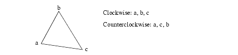
Face orientation.
The orientation in which you choose to enter the faces is not important; however, the faces in a single shell should all have the same orientation. One reason for this requirement is performance - HOOPS can create much longer tri-strips if all faces in a shell have the same orientation.
A second reason that all faces should have the same orientation is so that the object has a consistent handedness. This will enable you to set a polygon handedness, and also use backplane culling to throw away back-facing faces using the “face culling” heuristic (refer to the next section, along with the Set_Heuristics command for more information).
If the faces in a shell do not all have the same orientation, HOOPS Visualize will issue a warning. Note that some applications that produce tri-strips generate the tri-strips with alternate faces oriented in opposite directions - and that is the absolutely worst case with respect to maximizing tri-strip length.
The Compute_Optimized_Shell routines supports an option called “fix handedness”, which converts all faces to the handedness that represents the pre-fix majority. There is also a program called fixshell.c in the demo/common/standard directory of the HOOPS Visualize distribution that shows how to reorient the faces of a shell.
Polygon Handedness and Backplane Culling
Polygon handedness refers to the orientation of the faces in a shell defining which side is ‘front’ and which is ‘back’. For example, wrap your right hand in the direction of the point ordering for a face in the shell (all faces should be ordered in the same way). The direction of your thumb denotes the ‘front’ side of the face (thus the ‘front’ denotes the ‘outside’ of a shell if it’s a closed object). If your thumb is currently pointing in the correct direction for your object, then it has ‘right handed’ polygons. If it’s pointing in the wrong direction (inward!), then your object has ‘left handed’ polygons.
It is set via the “polygon handedness” option in Set_Heuristics. If you are using the OpenGL driver, you should always set a polygon handedness on your models because it improves general rendering performance and is the prerequisite for the use of “display lists” which are an option in Set_Rendering_Options. Display lists can provide significant performance with most graphics cards. Their usage is discussed in detail on this page.
Polygon handedness is a property of the model. It’s possible that shells may have different values (some may be ‘left’, some may be ‘right’). If you know that all your shells have the same handedness, then you should place the polygon handedness setting at the top of your model hierarchy. To use polygon handedness to maximize effect in optimizing rendering performance, set the following properties:
- Define your shells with a consistent handedness.
- Set a polygon handedness.
- If an object has a polygon handedness and is closed (watertight, like a sphere), then you can additionally set the “face culling = back” option in
Set_Heuristics. This tells the system to cull away faces whose normal points away from the camera view vector (the backside faces; think of the dark side of the moon). This improves performance. - Turn on “display lists”.
Backplane culling is set via the “face culling” option in Set_Heuristics. It could also be considered a property of the model, and the following steps would be a good approach for setting this attribute:
- For objects that may not be ‘closed’, such a flat plate, you probably don’t want to enable backplane culling. Otherwise, their faces would disappear as you orbited to their ‘back’ side. You should specifically set ‘no face culling’ for these objects in the model hierarchy.
- Have a mechanism to toggle backplane culling in your top level ‘view’ segment with the default setting as ‘on’.
- You may want to insert a cutting plane in the scene, or make an object transparent. In these cases, you would probably want to see the ‘inside’ or back of the object rather than have it get culled away. Thus, you would turn backplane culling off at a top level and lock that attribute down the tree using the “attribute lock” option of
Set_Rendering_Options.
Selectability of Backplane-Culled Geometry
Backplane culling is different from other types of culling. It uses a different internal algorithm, therefore, using it with selection is a special case. First of all, the “selection culling” heuristic has no effect on backplane-culled geometry. Secondly, backplane culling does not work with Compute_Selection_By_Ray. But you can force Visualize to either select or ignore backplane-culled objects in other ways.
One way to force selection of backplane-culled geometry is to set the list parameter of Set_Selectability to “v!” in the segment where you are performing the selection:
HC_Set_Selectability("geometry=v!");
The “v!” directive will make geometry selectable even if it is not drawn.
Alternatively, you can use the action parameter of Compute_Selection to get the result you desire. Below is a simple code snippet which performs a selection on an object drawn at the point (0, 0):
// uses the selection settings for the segment
int result1 = HC_Compute_Selection(".", ".", "v", 0, 0);

// backplanes are not selectable, even if they are drawn
int result2 = HC_Compute_Selection(".", ".", "v, backplane culling", 0, 0);

// backplanes are selectable, even if not drawn - similar to "v!"
int result3 = HC_Compute_Selection(".", ".", "v, no backplane culling", 0, 0);
As with other selections, remember that unless you specify the starting segment for the selection (second parameter of Compute_Selection - “.” in this case), the selection algorithm will look for the nearest driver segment for its selection instructions.
Vertex Sharing
A shell consists of a list of vertices and a list of faces. The face list consists of a list of indices into the vertex list. If two faces share a common edge (which is common in shells), then these two faces should share some of their vertices in the vertex list. For example, a shell representing a cube should be defined with a vertex list containing eight vertices and a face list containing six faces, with each vertex shared by three different faces.
Of course, sharing of vertices is not required. It is perfectly legal to define a cube by specifying the four vertices for each face separately. In such a definition for a cube, the vertex list would contain four vertices for each face, or 24 vertices instead of eight. In addition to wasting space, failing to share vertices makes it much harder for HOOPS Visualize to form long triangle strips, and thus can slow down rendering significantly.
Thus, you should share vertices whenever possible. Visualize also provides a command, Compute_Optimized_Shell, that removes redundant vertices from the vertex list.
Data Reduction
Level of detail HOOPS’ level of detail capabilities can be leveraged to create polygon decimated variants of shells, which in turn improve rendering performance since fewer triangles are drawn. Level of detail representations are typically created for the purposes of allowing HOOPS/MVO ‘constant framerate’ logic to operate more effectively.
Skinning Fields such as FEA and GIS frequently contain graphical representations of data that contain internal faces. For example, the FEA field involves the use of ‘meshing’ tools which may create 3D volumetric meshes. (similar to a Rubik’s Cube) The HOOPS Visualize shell primitive can be used to represent this object. However, if the end-user is visualizing the object with face’s visible and can only see the surface/skin of the object, then HOOPS/3dGS is spending excess time drawing the internal faces which can’t be seen. It would be more optimal to have a variant of the object which just contains the faces on the surface, or ‘skin’ of the object.
The routine Compute_Optimized_Shell supports an option called ‘skin’ which will cause it to abandon its normal goal of merging nearby vertices in favor of extracting the exterior surface from shells that also have interior vertices and faces. This routine enables creation of the skin variant of the shell. You would modify your code to display the skin variant as long as the current rendering settings do not allow the user to see internal faces. If the user wanted to see a wireframe representation, you could then switch to the full 3D ‘volume’ variant (the variant containing internal faces).
Point Cloud Guidelines
For cases in which you want to render point cloud data which often consists of a large number of data points, we suggest that you present these data points as vertices in a shell. This shell without a face list then can be rendered with significantly high performance without sacrificing detail by calling to Set_Variable_Marker_Size, setting the “marker drawing” option in driver options and “vertex decimation” in rendering options with appropriate values. This is discussed in the detail in the section on vertex markers.

