Lines
HOOPS has three ways to insert lines: single lines, polylines, and ink.
Single Lines
A single line is a straight line segment. For example, to insert a line that goes from the origin to 1 unit in the y direction, use
HC_Insert_Line(0.0, 0.0, 0.0, 0.0, 1.0, 0.0);
Polylines
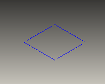
A polyline is a sequence of connected line segments. The following code draws a unit square centered about the origin:
    Point pts[5] = {
        {-0.5, -0.5, 0.0}, // lower left
        {0.5, -0.5, 0.0}, // lower right
        {0.5, 0.5, 0.0}, // upper right
        {-0.5, 0.5, 0.0}, // upper left
        {-0.5, -0.5, 0.0} // lower left
    };

    HC_Insert_Polyline(5, pts);
Notice that the first point had to be repeated at the end to close the figure, because polylines are not assumed to be closed.
Disjoint Polylines
Sometimes it is useful to insert a collection of disjoint line segments into the scene graph as one element. To do this, you can also use HC_Insert_Polyline. Pass your list of points as you would for a continuous line. For the point count, pass an even negative number to indicate that this is a disjoint polyline. HC_Insert_Polyline will return a negative count for the number of lines inserted. The following code draws a perforated square inserted as a disjoint polyline using HC_Insert_Polyline.
        Point pts[8] = {
            {-0.5, -0.5, 0.0}, // start point for first line segment
            {0.5, -0.5, 0.0}, // end point for first line segment
            {0.5, -0.4, 0.0}, // start point for second line segment
            {0.5, 0.4, 0.0}, // end point for second line segment
            {0.5, 0.5, 0.0}, // start point for third line segment
            {-0.5, 0.5, 0.0}, // end point for third line segment
            {-0.5, 0.4, 0.0}, // start point for fourth line segment
            {-0.5, -0.4, 0.0} // end point for fourth line segment
        };

        HC_Insert_Polyline(-8, pts);
A perforated square inserted into the scene as a disjoint polyline.
Infinite Lines
An infinite line is a line that has no beginning or end. It extends indefinitely into space. To draw an infinite line, call Insert_Infinite_Line and specify two points that lie on the line as shown in the following code snippet:
HC_Insert_Infinite_Line(0, 0, 0, 1.0, 1.0, 0);
Note that infinite lines are considered unbounded geometry. Thus, they will be ignored in bounding calculations.
Infinite Rays
An infinite ray is a line that has a beginning but no end. In other words, it has a starting point and then extends indefinitely into space in one specific direction. To draw an infinite ray, call Insert_Infinite_Ray and specify two points. The first point defines the beginning of the ray while the second point specifies a location in which the ray passes through as it extends to infinity. The following code sample shows how you can define a set of five infinite rays. In the figure below, you can see these rays rendered in HOOPS Visualize.
    HC_KEY rays_key = HC_Open_Segment("infinite_rays");
    HC_Insert_Infinite_Ray(0.0, 0.0, 0.0, 1.0, 0.0, 0.0);
    HC_Insert_Infinite_Ray(0.0, 1.0, 0.0, 1.0, 1.0, 0.0);
    HC_Insert_Infinite_Ray(0.0, 2.0, 0.0, 1.0, 2.0, 0.0);
    HC_Insert_Infinite_Ray(0.0, 0.0, 0.0, 0.0, 1.0, 0.0);
    HC_Insert_Infinite_Ray(0.0, 0.0, 0.0, 0.0, 0.0, 1.0);
    HC_Close_Segment();
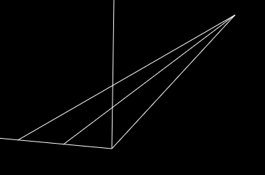
Shows five infinite rays rendered in perspective projection.
Note that infinite rays are considered unbounded geometry. Thus, they will be ignored in bounding calculations.
Ink
An alternate way to insert a polyline is with the Insert_Ink command. Ink works like the ink coming out of a pen on a pen plotter. The first call to Insert_Ink moves the hypothetical pen to its starting position. Each subsequent call to Insert_Ink moves the pen to a new position, inking a straight line segment as it goes. For example, to draw the same square in the above code, given the same array, you can use:
    for (int i = 0; i < 5; i++)
        HC_Insert_Ink(pts[i].x, pts[i].y, pts[i].z);
The advantage of ink is that you do not need to construct an array of points. For example, you can read in coordinates from a file, and ink each one without having to wait until the entire file is read so that you can allocate an array for all the points. You do not even have to ink the entire polyline at the same time - you can close the segment being inked, and later can come back to it and resume inking where you left off.
You can terminate the line by calling Restart_Ink. After that, the next call to Insert_Ink will start a new polyline.
HOOPS also allows you to remove vertices that were added by calls to Insert_Ink. If Restart_Ink has not been called for a given polyline created by Insert_Ink, you can use Rollback_Ink to “erase” a specified number of vertices starting with the most recently added one.
A polyline drawn via ink is considered to be multiple form, even though each line segment is drawn with its own HOOPS commands. That is, an inked polyline is equivalent to a regular polyline in all respects, but both are different from a sequence of calls to Insert_Line.
Line Attributes
You can change the width of a line using Set_Line_Weight. The default weight is 1.0, which is usually a line one pixel wide (except on very-high-resolution devices - greater than 1000 pixels high - when it is one-thousandth of the screen height). You can force the line to be the minimum possible (a hairline) by specifying 0 as the line weight. This causes lines to be drawn in a fixed (screen space) size, and they will not scale as the object scales. However, HOOPS/3dGS also supports line weights which will scale as the object is scaled or the camera changes. This is enabled by calling Set_Variable_Line_Weight.
You can make a line dashed with Set_Line_Pattern. The pattern is (usually) specified figuratively. For example, here are a few possible line patterns:
    HC_Set_Line_Pattern("----"); // solid
    HC_Set_Line_Pattern("- -"); // simple dashed line
    HC_Set_Line_Pattern("-- --"); // long dashes
    HC_Set_Line_Pattern(". . ."); // dotted line
    HC_Set_Line_Pattern("-.-."); // dashes and dots
    HC_Set_Line_Pattern("center"); // drafting centerline
There are other line patterns available - see the HOOPS Reference Manual entry for Set_Line_Pattern for details.
Lines with a weight greater than 1.0 are able to have line treatments. You can treat the ends of lines, and, for a polyline, you can treat how the individual segments join. The end cap of a line is specified as a prefix, and the line join is specified as a suffix, on the line pattern; you must specify a pattern to specify a treatment. For example, to round the ends of a solid line, and to mitre the joints where the line segments of a polyline meet, specify
HC_Set_Line_Pattern("(-->");
- The leading parenthesis “(” specifies that the ends are to be rounded, the
- two dashes “–” specify a solid line pattern, and the trailing angle bracket (greater-than sign) “>” specifies that the individual segments are to be joined with a mitre joint. The result looks something like the image below.

Polyline with line treatments.
You can change the color and visibility of lines just the way you might expect. For example:
    HC_Set_Color("lines=green");
    HC_Set_Visibility("lines=off");
Although you can set the color for lines and polylines, color interpolation is not available for this primitive. However, you can achieve the effect of color interpolated lines via color interpolation with polycylinders.
Custom Line and Marker Styles
HOOPS/3dGS includes support for defining custom line and marker styles.
Custom Markers
We’ll start reviewing the custom marker style functionality since that is used as a basis for custom line styles. Custom markers are specified by defining acustom glyph using Define_Glyph, and then setting the marker style to be the glyph name.
The following code example defines 4 glyphs, and inserts 4 markers with each one using a different glyph as a custom marker style:
    char const crosshairs[] = {10, 0, 0, 2, char(-10), 0, 10, 0, 2, 0, char(-10), 0, 10, 0};
    char const empty_box[] = {10, 0, 0, 5, 10, 10, 10, char(-10), char(-10), char(-10), char(-10), 10, 10, 10, 0};
    char const filled_box[] = {
        10, 0, 0, char(-1), 5, 10, 10, 10, char(-10), char(-10), char(-10), char(-10), 10, 10, 10, char(-3), 0};
    char const filled_red_ellipse[] = {
        100, 0, 0, char(-1), char(-10), 127, 0, 0, char(-4), char(-120), char(-120), 120, 120, char(-3), 0};

    HC_Open_Segment("my_segment");

    HC_Define_Glyph("crosshairs", sizeof(crosshairs), crosshairs);
    HC_Define_Glyph("empty_box", sizeof(empty_box), empty_box);
    HC_Define_Glyph("filled_box", sizeof(filled_box), filled_box);
    HC_Define_Glyph("filled_red_ellipse", sizeof(filled_red_ellipse), filled_red_ellipse);

    HC_Open_Segment("crosshairs");
    HC_Set_Marker_Symbol("crosshairs");
    HC_Insert_Marker(-0.5, 0.0, 0.0);
    HC_Close_Segment();

    HC_Open_Segment("empty_box");
    HC_Set_Marker_Symbol("empty_box");
    HC_Insert_Marker(-0.2, 0.0, 0.0);
    HC_Close_Segment();

    HC_Open_Segment("filled_box");
    HC_Set_Marker_Symbol("filled_box");
    HC_Insert_Marker(0.2, 0.0, 0.0);
    HC_Close_Segment();

    HC_Open_Segment("filled_red_ellipse");
    HC_Set_Marker_Symbol("filled_red_ellipse");
    HC_Insert_Marker(0.5, 0.0, 0.0);
    HC_Close_Segment();

    HC_Close_Segment();
The result is:
Custom Lines
The custom line style functionality is considerably more sophisticated. First review the reference manual entry for Define_Line_Style. The following examples are taken from the reference manual entry:
Example 1:
A solid line (specifically, a dash without blanks) of weight=1 is the default parallel. Therefore the line style resulting from an empty string passed as the definition will be a single, solid line of weight one (1 pixel). However, let’s say we want to create the default solid line style with triple weight:
    HC_Define_Line_Style("thick_solid_line", "3 pixel weight, dash");
    HC_Set_Line_Pattern("thick_solid_line");
    HC_Insert_Line(-0.5, 0.0, 0.0, 0.5, 0.0, 0.0);
The result:
Example 2:
The double-line version of the above example, with a 20 pixel separation, would look like this:
    HC_Define_Line_Style("double_solid_line", "2 pixel weight, dash, parallel, 20 pixel offset, 2 pixel weight, dash");
    HC_Set_Line_Pattern("double_solid_line");
    HC_Insert_Line(-0.5, 0.0, 0.0, 0.5, 0.0, 0.0);
Example 3: The following example creates and sets a scalable line pattern that alternates between a line segment, a blank, and a line segment in the segment’s contrast line color:
    HC_Define_Line_Style("myLineStyle", "0.1 oru dash, 0.1 oru blank, 0.1 oru contrast");
    HC_Set_Color("lines=red, line contrast=blue");
    HC_Set_Line_Pattern("myLineStyle");
    HC_Insert_Line(-0.5, 0.0, 0.0, 0.5, 0.0, 0.0);
Example 4: Let’s define a custom line style which has arrowheads at either end. We’ll first specify the array which defines the glyph for the arrowhead:
const char Arrow[] ={10, 0, 0, -1, 4, -10, 0, 0, 10, 10, 0, -10, 0, -3, 0};
The array entries are as follows:
| 10 | radius |
| 0,0 | offset |
| -1 | start fill |
| 4 | point count |
| -10,0 | point 1 |
| 0,10 | point 2 |
| 10,0 | point 3 |
| -10,0 | point 4 |
| -3 | end fill |
| 0 | terminate glyph |
Now we’ll define the custom glyph and line style, and insert a line with the new style:
    char const Arrow[] = {10, 0, 0, char(-1), 4, char(-10), 0, 0, 10, 10, 0, char(-10), 0, char(-3), 0};

    HC_Define_Glyph("triangle", sizeof(Arrow), Arrow);
    HC_Define_Line_Style("myLineStyle", "arrows = 0.1 oru triangle, dash");
    HC_Set_Line_Pattern("myLineStyle");
    HC_Insert_Line(-0.5, 0.0, 0.0, 0.5, 0.0, 0.0);
Example 5: Using parallels, we can easily create a triple-line style:
    HC_Define_Line_Style("myLineStyle", "dash, parallel, 0.05 oru offset, contrast, parallel, -0.05 oru offset, contrast");
    HC_Set_Color("lines=red, line contrast=blue");
    HC_Set_Line_Pattern("myLineStyle");
    HC_Insert_Line(-0.5, 0.0, 0.0, 0.5, 0.0, 0.0);
Example 6: This example uses the “fixed” setting to force one of the parallels to be always 5 pixels from the center-line, while the other will be affected by the local line weight and consequently be 10 pixels from the center-line.
    HC_Define_Line_Style("myLineStyle", "dash, parallel, 5 pixel fixed offset, contrast, parallel, -5 pixel offset, contrast");
    HC_Set_Color("lines=red, line contrast=blue");
    HC_Set_Line_Pattern("myLineStyle");
    HC_Set_Line_Weight(2);
    HC_Insert_Line(-0.5, 0.0, 0.0, 0.5, 0.0, 0.0);
Transformable Lines
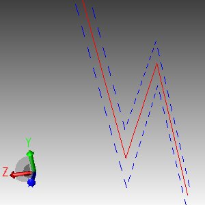
All the preceding examples describe custom lines that are projected onto the plane of the screen. A result is that, on the screen, line offsets maintain a fixed distance from center lines and glyphs are always screen-facing regardless of the camera or 3D line orientation. While this is useful in some situations, in other cases you might want to render offset lines and glyphs such that they appear to be lines in 3D space, not screen space. Note that these lines are still temporary geometry – they do not exist in the HOOPS database on any permanent basis. To do this in HOOPS/3DGS, use the pattern keyword ‘transformed’ when defining a line using Define_Line_Style.
HC_Define_Line_Style("dashing line pattern", "0.3 oru offset, dash, transformed");
|
|
|
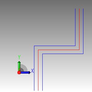
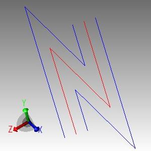
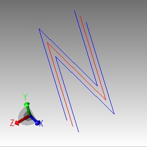
The image on the far left shows a custom polyline as viewed from the top down. The middle image shows the polyline rendered aligned with screen. Note that the offsets appear flush with center line at the ends of the polyline. The image on the far right shows the same line rendered with a projection plane applied to the offset. Consequently, the offsets do not appear flush with the center line at the ends of the polyline.
To create the 3D effect for your custom line, HOOPS projects the line pattern onto an arbitrary plane. The default plane is defined by the normal (0,0,1) and up vector (0,1,0), however, this may not provide the desired appearance for your line pattern. You can use the Set_Geometry_Options method to define the orientation plane onto which you want your line pattern to projected. If you specify one vector to orient your line pattern, then HOOPS Visualize assumes that the vector is normal to the plane you want to project onto. If you specify two vectors to orient your line, HOOPS Visualize assumes the first vector is the normal and the second vector is an up vector. By specifying an up vector, you can specify a full 3d orientation for glyphs in patterns. Note that geometry options are assigned on a per-geometry basis (not on a segment) and thus are not inherited or shared amongst geometries in a segment like other attributes. Be aware that since these patterns are the result of 3D lines being projected onto a 2D surface, some surprising results may occur when using transformed patterns with offsets on polylines that do not lie in a single plane.
    // This call sets a normal vector of (1,0,0) and an up vector of (0,0,-1)
    HC_Set_Geometry_Options(key, "orientation=(1,0,0, 0,0,-1)");
|
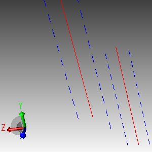
|
These three images show a polyline rendered with the same line style but different orientations. In some cases, parts of the pattern may not appear visible at all as seen in the second image from the left whose middle section is invisible because the orientation plane normal is (1,0,0) which is parallel the middle segment. The third image only has its middle section visible due to the same reason.
When defining orientation for line styles that use glyphs, use the “fixed” keyword to indicate to HOOPS/3DGS that you want your glyphs to orient themselves via the orientation vectors define is Set_Geometry_Options as opposed to the polyline as shown in the following code sample.
HC_Define_Line_Style("glyph line pattern", " 0.1 oru glyphName, fixed,transformed");
The image on the left shows five polylines with glyphs in their custom line styles. The image on the right shows the glyphs in each progressive line from left to right can be rotated by defining the orientation in ``Set_Geometry_Options``.
Modulating Custom Lines
With Define_Line_Style, you can create a variety of custom designs for your lines with predefined markers as well as specialty glyphs. Then, they can be applied to any segment using Set_Line_Pattern.
This function offers some latitude to alter your custom line style during its application but there are limits including no option to change a start or end glyph. However, HOOPS offers the ability to modulate all the available parameters in Define_Line_Style and Set_Line_Pattern with the Set_Line_Pattern_Explicit function.
With Set_Line_Pattern_Explicit, you can set and/or change the following options on a line style:
- “arrows”
- “start glyph arrow”
- “end glyph arrow”
- “caps”
- “start cap”
- “inner cap”
- “end cap”
- “glyphs”
- “start glyph”
- “middle glyph”
- “end glyph”
- “join”
If at any point, you want to revert to the initial line style defined via Set_Line_Pattern or Define_Line_Style, just call Set_Line_Pattern_Explicit and pass the unset_glyph “unset glyphs” option.
Clock Example Using Lines and Markers
We’ve now reviewed enough geometry types to draw a clock. Initially, we shall use lines for the clock hands, a polyline for the rim of the clock, text for the hour numerals, and a marker for the central hub.
This example begins with the definition of struct Point, and the inclusion of several standard header files. Remember that HC_POINT must be defined before hc.h is included:
1  struct Point {
2   float x, y, z;
3   Point & set_point(float xx, float yy,
4        float zz = 0.0) {
5   x = xx; y = yy; z = zz;
6   return *this;
7   }
8  };
9  #define HC_POINT Point
10   #include
11   #include
12   #include<stdio.h>
Initial Definitions
The next part of our example defines the main function. First, we open the segment “?Picture” and set options on it:
13  void main() {
14   HC_Open_Segment("?Picture");
15         HC_Set_Driver_Options(
16                 "subscreen = (-0.5, 0.5, -0.5, 0.5)");
17         HC_Set_Heuristics("no hidden surfaces");
Driver options and heuristics
The Set_Driver_Options command sets the size and location of the output window. The display is assumed to go from -1 to +1 in each dimension, so this command creates a window that is one-half of the height and width of the display, positioned in the middle of the display.
The heuristic Set_Heuristics_hidden_surfaces “no hidden surfaces” (line 17) tells HOOPS that the geometry that we will be using consists of lines and text, with no surfaces (no polygons or other filled objects). Thus, HOOPS does not need to perform hidden-surface calculations. We will get the same picture if we do not specify this heuristic, but it will usually be produced more slowly. It is always a good idea to specify this heuristic if your scene does not contain any hidden surfaces. This heuristic is discussed further in the rendering section.
Now we get into the heart of this example. Remember that the “?Picture” segment is currently open (it was opened on line 14):
18  // clock geometry
19  HC_Open_Segment ("clock");
20    HC_Set_Color("dark blue");
21    HC_Set_Text_Font(
22                "size = 0.1 oru, transforms");
Attributes on Picture
The color of the clock is set to dark blue, and the size of the hour numerals is set to 0.1 oru. Thus, the size of the numbers is set relative to the other objects in the scene, rather than relative to the size of the output window (the default). We also turn on text transforms, because in this case the text is part of the scene (numbers on the face of the clock), and is not just annotation:
23 const float rimr = 0.98f;    // radius of rim
24 const float numr = 0.80f;    // radius of nums
Size of the clock elements.
The constants rimr and numr control the distance of the edge of the clock and the numerals from the center of the clock. Since the output window goes from -1 to +1 in both the x and y dimensions, the clock will nearly fill the output window.
Lines 26 to 39 contain a loop from 0 to 12 (making a total of 13 iterations). Inside this loop, we use Insert_Ink to draw a polyline for the rim of the clock face, and Insert_Text to place the numerals for the hours:
25  // for each hour
26  for (int hour = 0; hour <= 12; hour++) {
27       double angle = hour * (3.14159/6.0);
28       float x = (float) sin(angle);
29       float y = (float) cos(angle);
30       // rim of face
31       HC_Insert_Ink(rimr * x, rimr * y, 0.0);
32       // hour numerals
33       if (hour > 0) {
34              char buffer[32];
35              sprintf(buffer, "%d", hour);
36              HC_Insert_Text(numr * x, numr * y, 0.0,
37                        buffer);
38        }
39   }
Clock rim and numerals.
The final part of the clock face is the central hub. For the hub we use a marker - a solid circle specified figuratively as “(*)” - whose color is set to reddish blue:
40  // central hub
41    HC_Open_Segment("hub");
42      // use solid dot for marker
43          HC_Set_Marker_Symbol("(*)");
44          HC_Set_Marker_Size(1.5);
45          HC_Set_Color("reddish blue");
46          HC_Insert_Marker(0.0, 0.0, 0.0);
47    HC_Close_Segment(); // hub
Central hub of clock.
Note that we have put the hub in its own segment, to keep its attributes separate from those of the rest of the clock. This separation is good programming style in HOOPS. In this example, however, the only attribute that conflicts is the color of the hub, so we could have left everything in the same segment and set the marker color with the command
HC_Set_Color("markers = reddish blue");
If we later change the hub from a marker to a polygon, it is easier to find and change the attributes that apply to it if the hub is in its own segment.
Next, we create the clock hands. Each hand has a different line-weight attribute, so each must be in a separate segment. But both hands are red, so we create a separate parent segment to hold the common color attribute:
48         HC_Open_Segment("hands");
49               HC_Set_Color("red");
50               HC_Open_Segment("minute hand");
51                 HC_Set_Line_Weight(2.0);
52                 HC_Insert_Line(0.0, -0.2, 0.0,
53                         0.0, 0.7, 0.0);
54               HC_Close_Segment(); // minute hand
55               HC_Open_Segment("hour hand");
56                 HC_Set_Line_Pattern("(--");
57                 HC_Set_Line_Weight(4.0);
58                 HC_Insert_Line(0.0, -0.1, 0.0,
59                        0.0, 0.5, 0.0);
60           HC_Close_Segment(); // hour hand
61         HC_Close_Segment(); // hands
62    HC_Close_Segment(); // clock
63  HC_Close_Segment(); // ?Picture
64  HC_Pause();
65 }

