
Texture Mapping
Creation of an Image for a Texture
A texture map is created from a HOOPS image. Consequently, the first step in defining a texture map is to create a HOOPS image using the Insert_Image command. The image data can be created from raw data created by your application, or it can be read in from a file. To use an image as a texture map, however, you must name the image.
The Insert_Image command takes seven arguments:
HC_Insert_Image(x, y, z, format, width, height, data);
The first three arguments specify the coordinates of the image location and the final three arguments are the image’s width and height, and the actual image data. We recommend that your image’s dimensions be square and a power of 2. This will ensure the best rendering performance possible. If your image does not fall into this category, HOOPS, by default, will downsample the image to the next appropriate size. For example, if an image exceeds 512x512, then HOOPS will downsample it into that size buffer. To prevent downsampling, use the fourth argument in Insert_Image. This parameter normally gives information about whether the image data contain RGB triples or indices into a color map. However, you can also specify texture options like “no down-sampling”. Passing this option prevents the degradation of your image. However, setting this option has performance costs because HOOPS will likely upsample your image to a larger buffer.
You can also use the fourth argument to give a name to the image - for example,
HC_Insert_Image(0, 0, 0, "RGB, name=my_image", width, height, data);
This image has been given the name “my_image”.
If you plan to use an image as a texture, then you probably do not want the image itself to be visible. Either the image can be placed into the HOOPS database in a segment that is not under a driver, or else you can put it into an arbitrary segment and turn off the visibility of the segment. In either case, the actual values of the x, y, and z coordinates supplied to the Insert_Image command are irrelevant.
NOTE: Although most images that have a dimension that is not a power of two are downsampled, there is one exception is with very small textures. The smallest texture size is 16x16, therefore, if your texture is smaller than this, it will be upscaled to 16x16.
Use of an Image as a Backdrop
The simplest way to use a named image is as a window backdrop. You can use an image as a backdrop by using the image name as the window color. The following code snippet creates an image inside a segment named “/image”. Because this segment is directly under the root segment, rather than under a driver segment (such as “?Picture”), the image will not be visible. The image is named “stop_sign”. This image name is then used as the window color of “?Picture” and is stretched to fill the window.
    HC_Open_Segment("/image");
    HC_Insert_Image(0, 0, 0, "RGB, name = stop_sign", width, height, data);
    HC_Close_Segment();

    HC_Open_Segment("?Picture");
    HC_Set_Color("window = stop_sign");
    HC_Close_Segment();
Use of a named image as a window backdrop.
Use of an Image as a Texture
Using an image as a texture on an object is only slightly more complicated than is using it as a window backdrop. A texture map can be applied to a shell or a mesh, but using a texture map with a mesh is simpler and more common. You can create a texture map from an image and set it by performing the following steps:
- Insert an image and give it a name via
Insert_Image. When an image is inserted and given a name, HOOPS automatically creates a texture based on that image giving it the same name. - Specify a parameterization source. To apply a texture to a surface, each pixel of the rendered surface must be “mapped” to a texel in the texture source. You can specify the type of mapping via the parameterization source option in your call to
Insert_Image. If you do not know which parameterization source will be used for your texture map at the time of insertion, you can update it or any other texture options withEdit_Image_Options. - Make sure that the “texture interpolation” rendering option is enabled (it is enabled by default).
- Assign texture-coordinate parameters to the shell or mesh, to control the mapping between points on the surface of the object and points in the texture.
- Use the “image as the color” of the object; for example,
Set_Color("faces = (diffuse = my_new_texture)");.
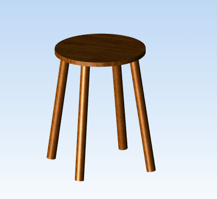
A stool with a wood texture applied to it.
The following sample code shows how to specify a parameterization source of a texture that was automatically created from an inserted image.
    HC_Open_Segment("");
    HC_KEY imageKey;

    // Inserting the image
    imageKey = HC_Insert_Image(0, 0, 0, "RGB, name= cedarGrain", width, height, data);

    // Setting the parameterization source
    HC_Edit_Image_Options(imageKey, "texture options=(parameterization source= natural uv)");
    HC_Close_Segment();
Using an image and texture map in this tightly coupled way can be very convenient. However, it is also useful to be able to create multiple texture maps with different parameterization sources that are based on the same source image. To create a texture map explicitly, use the Define_Texture function and pass the image name for source parameter.
Texture-coordinate parameters and parameterization source
To apply a 2D texture to a 3D surface, you must define how points on the 3D surface map onto points in the texture. You make that determination by assigning a texture-coordinate parameter to each vertex in the shell or mesh. HOOPS/3dGS happens to have built in support for cylindrical, spherical and ‘natural’ mappings. HOOPS/3dGS will automatically calculate and assign the texture-coordinate parameters if you choose either the ‘sphere’, ‘cylinder’, or ‘natural uv’ parameterization source:
HC_Define_Texture("my_texture", "parameterization source = [sphere/cylinder/natural uv]");
All other parameterization sources requires that you manually apply texture-coordinate parameters to an individual vertex in a shell or mesh by opening the shell or mesh (using Open_Geometry), then opening a vertex (using Open_Vertex), and then setting the texture-coordinate parameter using the ::Set_Parameter command. The use of Set_Parameter is identical to the way that colors are set on individual vertices in a shell or mesh. Alternatively, you can use the MSet_Vertex_Parameters command to set texture-coordinate parameters on multiple vertices.
A texture coordinate specifies a pixel location in the texture to use as the color of the object. Regardless of the size (in pixels) of an image used as a texture, the texture coordinates are assumed to go from 0.0 to 1.0 in both x and y. In addition, texture coordinates are 3D points, but the z coordinate is ignored. If a vertex has a texture-coordinate parameter of (0.0, 0.0), then the color at that vertex is taken from the pixel at the lower-left corner of the texture image. Likewise, if a vertex has a texture-coordinate parameter of (1.0, 1.0), then the color at that vertex is taken from the pixel at the upper-right corner of the texture image.
Textures in Driver Segments
Due to the way that HOOPS handles colors, you can sometimes get incorrect images if you apply a texture to a shell or mesh that is contained in a driver-instance segment (such as “?Picture”). The easiest way to avoid this problem is to put the geometry into a subsegment.
Example Program With a Texture
Most of the code in the following snippet defines the mesh for the cylinder. The parts that are for applying the texture map are lines 25 through 33, which define the array of texture coordinate parameters for the points in the mesh; line 36, which applies the texture coordinate parameters to the mesh; and line 39, which uses the image as a texture for the faces of the mesh. The texture coordinate parameters are defined such that the texture wraps around the cylinder.
Note that line 4 (which turns on texture interpolation) also turns off color interpolation and color-index interpolation. We often turn off interpolation when we are using texture mapping, since we want the colors to be taken from the texture, rather than interpolated from the vertex colors. Also note line 37, which turns off the visibility of edges and markers. HOOPS will happily apply a texture to the edges of a shell or mesh, but that texture application takes time to compute. Applying the texture to only the faces results in exactly the same picture as would applying the texture to faces and edges, and is much faster.
    struct Point {
        float x, y, z;
    };

    HC_Open_Segment("?Picture");
    HC_Set_Rendering_Options("no color interpolation, no color index interpolation, texture interpolation");
    HC_Set_Color("windows = black");

    // tessellate a cylinder
    HC_Open_Segment("cylinder");
    static Point point_list[42];
    static Point params[42];
    double const angle = 3.1415926535 / 10.0;

    // create two circles in x,z plane
    for (int loop = 0; loop <= 20; ++loop) {
        // circle at top of cylinder
        point_list[loop].x = (float)cos(loop * angle);
        point_list[loop].y = 1.0f;
        point_list[loop].z = (float)sin(loop * angle);

        // circle at bottom of cylinder
        point_list[loop + 21].x = point_list[loop].x;
        point_list[loop + 21].y = -1.0f;
        point_list[loop + 21].z = point_list[loop].z;

        // texture map coordinates for top
        params[loop].x = (float)loop / 10.0f;
        params[loop].y = 1.0f;
        params[loop].z = 0.0f;

        // texture map coordinates for bottom
        params[loop + 21].x = params[loop].x;
        params[loop + 21].y = 0.0f;
        params[loop + 21].z = 0.0f;
    }
    HC_KEY key = HC_Insert_Mesh(2, 21, point_list);
    HC_MSet_Vertex_Parameters(key, 0, 42, 3, (float*)params);
    HC_Set_Visibility("no edges, no markers");
    HC_Scale_Object(0.8, 0.8, 0.8);
    HC_Set_Color("faces = image");
    HC_Close_Segment();
    HC_Close_Segment();
Using an image as a texture.
If our texture-mapped cylinder will be used in a scene with any lights, we will probably want to set the vertex normals (particularly on the seam), so that the lighting is done properly (appears smooth across the seam).
Texture-Coordinate Parameters on Shells
When you apply a texture to a shell, you may encounter problems, because you often need a vertex to have more than one texture-coordinate parameter. For example, if you used a shell for the cylinder, then the seam where the surface connects with itself will need to have two texture-coordinate parameters - one for the left side of the texture and one for the right side, as shown here:
Vertices with more than one texture-coordinate parameter.
The solution to this problem is simply to duplicate the vertices in the shell’s point list. That way, even though two points may have the same geometric coordinates, they can have different texture-coordinate parameters. Note that, when you duplicate vertices, you will probably want to set the normals on duplicated vertices explicitly.
Multiple Textures on a Shell
In HOOPS/3dGS, you can assign different textures to the individual faces of a shell. To begin, set the parameterization source to uv when defining your texture. This lets HOOPS know that you will be setting the texture-coordinate parameters on the vertices of your target shell.
To set the texture-coordinate parameters on your shell, you can use the MSet_Vertex_Parameters command. As noted in the previous section, when defining texture-coordinate parameters, each vertex can only have a single set of vertex parameters. Because it is possible for two or more points to have the same geometric location, we recommend that you define your vertices explicitly for each individual face.
Once you have created your textures and inserted your shell into the HOOPS database, you may assign each face an individual texture. Normally, to assign a texture to a face, you simply call HC_Set_Color("faces = texture_name"). However, this sets a texture for all the faces in a shell. To set a specific texture for a specific face, create a color map enumerating all the textures. Then, open the individual faces of the shell one by one using ::HC_Open_Face and then use HC_Set_Color_By_Index to set the texture.
In the code sample below, we create a six-sided die by inserting a cube and then applying different textures to each face. When we call Insert_Shell, instead of passing a point list that consists of eight vertices, we pass a point list with 24 vertices or 4 points for each face of the cube. Thus each geometric point is specified three times (once for each face that touches the point). This allows us to later use MSet_Vertex_Parameters to define the texture-coordinates explicitly. Then applying the individual textures via a color map is a straight forward operation.
        // Creating the points and face list for a cube. Note that instead of using an array of eight points,
        // we have create an array of 24 points such that each face has its on set of vertices for texture
        // parameterization later.
        int pcount = 24, flist_count = 30;
        HPoint pts[24];
        int faces[30] = {4, 0, 1, 2, 3, 4, 4, 5, 6, 7, 4, 8, 9, 10, 11, 4, 12, 13, 14, 15, 4, 16, 17, 18, 19, 4, 20, 21, 22, 23};

        // Face 1
        pts[0].Set(0, 0, 0);
        pts[1].Set(1, 0, 0);
        pts[2].Set(1, 1, 0);
        pts[3].Set(0, 1, 0);

        // Face 2
        pts[4].Set(0, 0, 0);
        pts[5].Set(1, 0, 0);
        pts[6].Set(1, 0, -1);
        pts[7].Set(0, 0, -1);

        // Face 3
        pts[8].Set(1, 0, 0);
        pts[9].Set(1, 1, 0);
        pts[10].Set(1, 1, -1);
        pts[11].Set(1, 0, -1);

        // Face 4
        pts[12].Set(1, 1, 0);
        pts[13].Set(0, 1, 0);
        pts[14].Set(0, 1, -1);
        pts[15].Set(1, 1, -1);

        // Face 5
        pts[16].Set(0, 1, 0);
        pts[17].Set(0, 0, 0);
        pts[18].Set(0, 0, -1);
        pts[19].Set(0, 1, -1);

        // Face 6
        pts[20].Set(0, 0, -1);
        pts[21].Set(1, 0, -1);
        pts[22].Set(1, 1, -1);
        pts[23].Set(0, 1, -1);

        HC_Open_Segment("");
        // Inserting the shell
        HC_KEY shellKey = HC_KInsert_Shell(pcount, pts, flist_count, faces);

        // Setting up the paramterization of our faces
        float params[][2] = {{0, 0}, {1, 0}, {1, 1}, {0, 1}};
        HC_MSet_Vertex_Parameters(shellKey, 0, 4, 2, (float*)params);
        HC_MSet_Vertex_Parameters(shellKey, 4, 4, 2, (float*)params);
        HC_MSet_Vertex_Parameters(shellKey, 8, 4, 2, (float*)params);
        HC_MSet_Vertex_Parameters(shellKey, 12, 4, 2, (float*)params);
        HC_MSet_Vertex_Parameters(shellKey, 16, 4, 2, (float*)params);
        HC_MSet_Vertex_Parameters(shellKey, 20, 4, 2, (float*)params);

        // Inserting the image for the faces of a die
        int height = 256, width = 256;

        // For the second parameter, we are passing in the name of the texture
        // as well as the parameterization. The uv parameterization source is used
        // for traditional image based texture maps. The parameterization source
        // comes from a user supplied (u,v) coordinate set with the
        // MSet_Vertex_Parameters() routine used above.
        HC_Insert_Image(0, 0, 0, "RGB, name= one, texture options =(parameterization source=uv)", width, height, data1);
        HC_Insert_Image(0, 0, 0, "RGB, name= two, texture options =(parameterization source=uv)", width, height, data2);
        HC_Insert_Image(0, 0, 0, "RGB, name= three, texture options =(parameterization source=uv)", width, height, data3);
        HC_Insert_Image(0, 0, 0, "RGB, name= four, texture options =(parameterization source=uv)", width, height, data4);
        HC_Insert_Image(0, 0, 0, "RGB, name= five, texture options =(parameterization source=uv)", width, height, data5);
        HC_Insert_Image(0, 0, 0, "RGB, name= six, texture options =(parameterization source=uv)", width, height, data6);

        // Setting up the color map for the textures
        HC_Set_Color_Map("one,two,three,four,five,six");

        HC_Open_Geometry(shellKey);
        for (int i = 0; i < 6; i++) {
            HC_Open_Face(i);
            // setting the textures to the individual faces of the cube
            HC_Set_Color_By_Index("faces", i);
            HC_Close_Face();
        }
        HC_Close_Geometry();

        HC_Close_Segment();
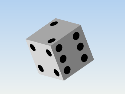
A die created by inserting a cube and laying different textures on the individual faces with a color map.
Other Texture Attributes
Although applying textures to surfaces can be relatively easy in HOOPS, there are numerous options and attributes that you can use to exercise a fine level of control over the texture maps in your application.
Use of Textures as Material Properties
Previously, we demonstrated how to use the image as the entire color specification for the faces of the mesh). It is also possible to use a texture map as one component of the color. For example, we can use one texture for the diffuse color, and another texture for the specular color. See the Set_Color command for more information.
Transformation of Texture-Coordinate Parameters
Normally, texture coordinates are fixed. When you move an object that has a texture applied to it, the texture moves with the object. You can also apply transformations to the texture coordinates. Normally, you transform texture coordinates with the commands Translate_Texture, Scale_Texture, Rotate_Texture, and Rotate_Texture_Offaxis. For example, you could use the Rotate_Texture command to rotate the limestone texture in our previous sample, so that the limestone blocks run up and down the cylinder, rather than around it (alternatively, you could specify different texture-coordinate parameters).
Note that the transformations set with Rotate_Texture and Translate_Texture will not be applied to textures that have the “transform override” option set when in Define_Texture. Instead, these textures will only take on transformations specified explicitly in the texture definition.
You can also use Scale_Texture to make the limestone blocks larger or smaller. If you apply the command…
HC_Scale_Texture(0.25, 0.5, 1.0);
…to the texture coordinates (by inserting it after line 47, you will create a more realistic-looking limestone-block cylinder.
Note that, unlike modeling-transformation matrices, and like most attributes, texture transformations in separate segments are not concatenated. Texture matrices act like normal attributes - a local one overrides an inherited one. Multiple rotate, scale, and translate texture commands in a single segment do accumulate, however.
You can set the texture-transformation matrix explicitly using the Set_Texture_Matrix command, and can remove any texture-transformation matrix using UnSet_Texture_Matrix. You can also concatenate a transformation matrix onto the texture-transformation matrix using the Append_Texture_Matrix command. See the HOOPS/3dGS Reference Manual for details.
Perspective Correction
Because texture coordinates are normally linearly interpolated in screen space, viewing objects that are texture mapped in perspective can cause the texture map to appear distorted. You can correct for this problem using the “perspective correction” rendering option (which is on by default).
Texture Modulating and Decaling
It is sometimes desirable to provide visual feedback that an object has been selected, but still maintain the textured appearance. For example, let’s say we wanted to highlight an oak-textured cabinet assembly by using a particiular ‘selection color’ to indicate highlighting, but still preserve the appearance of the wood grain by blending (modulating) the two. Alternately, it may desirable to ‘decal’ an object (consider the case of draping a logo onto a surface). This functionality is achieved by using HOOPS’ support for two diffuse color channels: one standard - “diffuse color” - and one specifically for textures - “diffuse texture” - which is a sub-channel of, and therefore inherits from, the standard diffuse color channel. Please see the 3DGS Programming Guide’s section Set_Explicit_Color for more details on how to set the diffuse texture for a given geometry.
Modulating
This is achieved by setting the color on the diffuse texture channel using the “diffuse color” sub-option, and making sure that the texture of interest is defined with the “modulate” option. The effect amounts to a tinting of the texture rather than a replacement of it. If the diffuse texture channel does not have an explicit color set, it will inherit the standard diffuse channel’s color and displace the texture.
Decaling
This is achieved by setting the color on the diffuse texture channel using the “diffuse texture” sub-option, and making sure that the texture of interest is defined with the “decal” option. Typically, the texture used for decal would be a texture containing opaque values at the locations of the decal, and alpha values everywhere else. (Imagine a rectangular clear sticker that has a flag or logo in the middle of it.)
Additional Texture Properties
The general use of textures can be complicated. HOOPS gives you full access to all the complexities of texture mapping via the Define_Texture command. Using Define_Texture, you can manipulate texture maps in almost any way imaginable. You can specify which coordinates of the texture-coordinate parameters to use, and you can even tell HOOPS to ignore the texture-coordinates parameter and to use the world coordinates of the vertex as the texture coordinate.
Note that, even if you use world coordinates as the texture coordinates, HOOPS still requires you to set a texture-coordinate parameter on a shell or mesh before it will perform texture mapping. Luckily, you can set a texture-coordinate parameter using the MSet_Vertex_Parameters command. Just set the pcount (third) argument to 0. Using
Define_Texture has many different options. One of the most useful is the “tiling” option, which specifies what to do if a texture coordinate is outside the 0.0 to 1.0 range. The default is for the texture to repeat itself over and over, tiling itself onto the surface to be textured. You can also set tiling to off, which clamps the texture coordinates, so only a single copy of the texture image appears on the surface. You can also set tiling to “mirror”, which causes every other copy of the texture image to be reversed. This option can sometimes help to hide the seams where copies of the texture image meet (however, most images in the texture-universe directory are designed to be seamless).
Another set of useful options are “interpolation filter” and “decimation filter”, which allow you to specify filters to reduce aliasing artifacts. Because a texture is just an array of pixels, when you zoom in close to a textured object, you will see individual pixels of the image. You can use an interpolation filter to interpolate between pixel values in the texture image, and thus to smooth out the texture. A decimation filter helps prevent such aliasing by producing lower resolution versions of the image.
Local Textures
The usage of Define_Texture described above makes the texture a ‘global’ texture. (Think of Define_Texture as a regular #define) You can’t have ‘global’ textures with the same name in different parts of the scene-graph. However, you can use Define_Local_Texture to make the texture ‘local’:
HC_Define_Local_Texture(<texture_name>, <definition>);
This setting makes the texture scoped to a segment and thus allows you to have textures with the same name in different parts of the scene graph.
Additionally, you can define a local texture by setting the following options in the Insert_Image interface:
- “[local | no local]” : If set, the implicit texture created will be local to the currently open segment.
- “[texture | no texture]” : Determines whether an implicit texture is created for this image.
- “texture options = ()” : Options for the implicit texture created for the image.
This saves you from having to define another texture if you want to change some options after inserting the image. The texture options are the same ones available in Define_Texture. The sample program local_texture.c in /demo/common/standard provides an example.

