
Cameras
In computer graphics, a camera, or viewpoint, is what allows us to view a scene. The camera is our surrogate, allowing us to “see” what the mathematical description of a scene in the graphics database actually looks like. It converts the objective world of a scene into the subjective world of an image.
In HOOPS, a camera is an attribute. As is true of any attribute, if you set the camera attribute on a segment, then that camera is inherited by the children of the segment, unless they explicitly override it with their own locally set camera. Each segment has a net value for the camera attribute - either a locally set camera or an inherited camera - and this net value is the camera used to view the geometry in that segment.
Like any attribute, the camera attribute can be set multiple places in the database. What does it mean for a scene to have more than one camera? Do you get more than one view of the same scene? No. Since each segment has only one net value for the camera attribute (as it does for any attribute), each piece of geometry in a scene will be viewed by only a single camera - the camera defined by its net camera attribute. Thus, different segments in a scene can be viewed by different cameras, but each segment will be viewed only once (unless that segment is included more than once in the scene via Include_Segment).
If you have trouble thinking of a camera as an attribute, remember that a camera is just a viewing transformation, which is used by the HOOPS driver to transform a scene from world coordinates into screen coordinates. The net value of the viewing transformation (the camera) for a particular segment is used to transform the geometry in that segment. Different segments can have different values for their net viewing transformation.
Camera Components
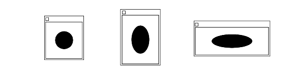
A camera attribute consists of several components. The components of a camera are shown below:
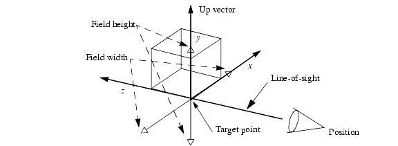
The components of a camera.
Position The position of the camera is a point that represents the position of the viewpoint (in world coordinates). Normally, the camera position is placed slightly away from the objects that you wish to view.
Target The target is a point (specified in world coordinates) toward which the camera is looking. The camera target is usually in the middle of the objects that you wish to view. The camera target must not be at the same position as the camera. The vector between the camera position and the camera target is called the line of sight.
Up Vector The up vector is a vector that defines “which way is up.” If you specified only the camera’s position and target, the camera could still rotate around the line of sight, so the up vector fixes the orientation of the camera. The up vector must not be all zeros, and cannot be parallel to the line of sight.
Logically, the up vector should be perpendicular to the line of sight. If it is not, the up vector is projected onto a plane perpendicular to the line of sight. The resulting projected vector is used to define the direction of the positive y axis on the screen.
Field The field of the camera comprises two numbers - a width and a height - that define the minimum area around the target that will be visible in the output window. The camera field, along with the distance between the camera position and the camera target, determine (in photographic terms) what kind of lens the camera is using. If the field is larger than the distance from the camera position to the target, then we have the equivalent of a wide-angle lens. If the distance between the camera position and target is much larger than the camera field, then we have the equivalent of a telephoto lens. Changing the size of the field (if the camera position and target remain fixed) is the same as zooming the lens.
The ratio of the width to the height of the field is called the aspect ratio.
Projection The projection determines how HOOPS represents the 3D coordinates of a scene using only the 2D coordinates on the screen. A perspective projection scales the x and y coordinates depending on the z coordinate (depth), such that objects that are farther away appear smaller on the screen. In an orthographic projection, the direction of projection is perpendicular to the camera target plane (so, the x and y coordinates aren’t scaled) Other projections are stretched, oblique perspective, and oblique orthographic. Oblique and stretched projections are discussed later.
Camera Inheritance
The components of a camera taken together inherit as a single attribute, unlike most other composite attributes, where each component inherits individually as though it were a separate attribute. For example, color and visibility are composite attributes that consist of components (such as face color and edge color); these components can be set individually and inherit separately.
When you set a new camera, it does not inherit any components from any camera attribute higher up in the database tree. Instead, the new camera completely overrides the inherited camera. If you later unset a camera attribute that was explicitly set on a segment, the segment goes back to inheriting the entire camera. You cannot unset an individual component of a camera.
The Default Camera
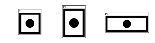
Of course, we have already been using a camera to view our graphics scenes, without explicitly creating one. As reviewed in the previous section, a camera is primarily a transformation that changes the graphics scene from the 3D world-coordinate system to 2D screen-coordinate system.
Since a camera is an attribute, HOOPS supplies a default value for it. Unless you explicitly set a camera attribute on a segment, the default camera is inherited by all segments in the database, and so is used to view all the segments in the database.
The default camera is positioned at (0.0, 0.0, -5.0), which is 5 units in the negative z direction. Recall that, in the left-handed coordinate system normally used in computer graphics, the positive z axis points away from the viewer. The camera’s target is the origin, and the up vector is (0.0, 1.0, 0.0) - the positive y axis. The field of the camera is 2.0 units wide and 2.0 high, and the projection is perspective. The default camera is shown here:
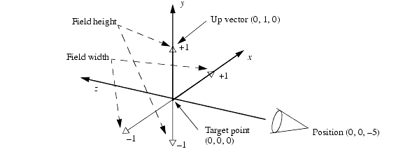
The default camera.
This default camera looks squarely at the x, y plane from 5 units away on the negative z axis, with “up” in the positive y direction; it sees a field that is a square 2 units per side, centered at the origin (between -1.0 and +1.0 on the x and y axes). Thus, if we define our objects such that they are centered at the origin, and are close to but no bigger than 1.0 unit in both their positive and negative x and y dimensions, then they will be viewed well by the default camera.
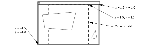
Mapping of the Camera Field to the Window
In review, the camera field defines a portion of the target plane. This is the minimum area around the target that will be visible in the output window. For example, the default camera defines a square field, whose width and height are both 2 units. This image shows how the default camera would map world coordinates onto a window on the screen:
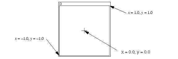
Default camera mapped to window
If the camera field is changed, then the portion of world space visible in the window will change. For example, we might have a scene that contains objects that range from +5 to -5 in both x and y (in world coordinates). Using the default camera, we would see only those objects that are within 1 unit of the origin. We can change the camera field such that its width and height are both 10 units (between +5 and -5).
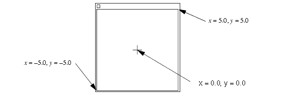
Non-default camera mapped to window
The center of the output window always corresponds to the target position in world coordinates.
Of course, the units/range applied to the world coordinates viewable in the window is completely arbitrary. For example, a molecular-modeling application might use coordinates with magnitudes such as 550 to represent nanometers, and would thus set the camera field to a size appropriately small; a civil engineering application might set the camera field to be 100000 meters wide, so that it could view an area 100 meters across.
It is usually a good idea to scale your application’s units such that your coordinates are neither extremely small nor immensely large. For example, it would probably be a bad idea to choose your units to be meters for an astronomy application (so you would have coordinates that were very large) or a molecular-modeling application (so you would have coordinates that were very small). Even though coordinates are floating-point numbers in HOOPS, most of the HOOPS defaults work best with coordinates that range close to +1.0 and -1.0. You can also run into numerical-accuracy problems when you mix numbers with different scales in the same computation, especially since HOOPS uses single-precision floating-point numbers to store coordinates.
Aspect Ratio
The ratio of the width to the height of a coordinate system is called the aspect ratio. For example, the default screen-coordinate system has an aspect ratio of 1 to 1 (defined by the width and height of the camera field). A window on the screen also has an aspect ratio. If the aspect ratio of the screen window exactly matches the aspect ratio of the camera field, then the camera field fits perfectly into the window, (the window border does not count).
When the user resizes the HOOPS output window on the screen, the aspect ratio of the screen window can change. In addition, your program can change the aspect ratio of the camera field (using Set_Camera_Field, Set_Camera_By_Volume, or Set_Camera). What happens when the aspect ratio of the window does not match the aspect ratio of the camera field? By default, HOOPS Visualize centers the camera field in the screen window, so that all the camera field is visible. Thus, the camera field defines the minimum area around the target in the scene that is guaranteed to be visible in the output window. HOOPS pads either the width or the height of the camera field as necessary to make the camera field fit the screen window.
For example, if the output window is resized such that it is 50 percent wider than it is tall (the aspect ratio becomes 1.5 to 1), then the y coordinates will range from -1.0 to 1.0 (as before), but the x coordinate will range from -1.5 to 1.5. HOOPS does not clip the scene to the camera field, so objects that are slightly outside of the camera field may become visible, as shown here:
Fitting of the camera field into a nonsquare window.
The camera field is indicated by dashed lines. These dashed lines do not actually appear in the HOOPS output window.
As you resize the output window of a HOOPS application, the output scene scales such that it gets larger and smaller as the window gets larger and smaller, but the relationship of x to y coordinates does not change. Thus, a circle continues to look circular, rather than getting fatter or skinnier (becoming an ellipse), as the output window gets wider or taller.
It is possible to tell HOOPS to keep the aspect ratio of the output window constant, using the “no subscreen stretching” option of the Set_Driver_Options command. When this option is in effect, the user can change the size of the output window, but the ratio of the window’s width to height will remain fixed. However, this only applies to HOOPS-created windows, and not to windows created by the user and passed into HOOPS. Since virtually all applications will take the latter approach (discussed later on), this option is not very applicable.
Modification of the Camera
You can modify the camera settings by changing the value of the camera attribute that applies to your scene. You can change the value by setting a camera attribute on the segment at the top of your scene, which is normally “?Picture”. That way, your new camera is inherited by all segments that are subsegments of “?Picture”, which includes all the visible objects in the scene.
The Set_Camera Command
HOOPS provides many different commands for working with cameras. Underpinning all these commands is the Set_Camera command, which modifies all five components of a camera at the same time. For example, say that we want to change the aspect ratio of the camera field to be the same as that of a standard definition monitor. A standard monitor has an aspect ratio of 4 to 3 (if it has a resolution such as 640 by 480, 800 by 600, or 1024 by 768).
The following program sets a camera attribute on “?Picture” that is the same as the default camera, except that the aspect ratio of the camera field is changed. Note that the field width and height can be any multiple of the aspect ratio. For the default camera with an aspect ratio of 1 to 1, the field width and height are both 2.0. To change the aspect ratio to 4 to 3, we leave the field height at 2.0 and change the field width to 2.667 (2 times 4 divided by 3).
    float position[] = {0.0, 0.0, -5.0};
    float target[] = {0.0, 0.0, 0.0};
    float up[] = {0.0, 1.0, 0.0};

    float field_width = 8.0 / 3.0;
    float field_height = 2.0;

    HC_Open_Segment("?Picture");
    HC_Set_Camera(&position, &target, &up, field_width, field_height, "perspective");
    HC_Close_Segment();
Changing of the camera field using Set_Camera.
In this example, we use Set_Camera to set the camera attribute on “?Picture”. If you want to modify a single component of the camera attribute but you do not know its current settings, you can show them with the Show_Net_Camera command. For example, this next code snippet changes the field width and height of the camera, but leaves the other components alone.
        Point position, target, up;
        float field_width, field_height;
        char projection[64];

        HC_Open_Segment("?Picture");
        HC_Show_Net_Camera(&position, &target, &up, &field_width, &field_height, projection);
        field_width = 8.0 / 3.0;
        field_height = 2.0;
        HC_Set_Camera(&position, &target, &up, field_width, field_height, projection);
        HC_Close_Segment();
Changing of part of a camera using Set_Camera.
Setting of a Single Component
HOOPS Visualize provides a number of routines for setting individual camera components. For example, the following command sets the camera field to have an aspect ratio of 4/3.
    HC_Open_Segment("?Picture");
    HC_Set_Camera_Field(8.0 / 3.0, 2.0);
    HC_Close_Segment();
This command behaves slightly differently, depending on whether a camera attribute has been set previously on “?Picture”. If “?Picture” already has a local camera attribute, this command will change only the camera field of that camera, and will leave the other components of the camera alone. But if “?Picture” does not have a local camera attribute, this command will create a new camera with all default values, change the camera field, and set this new attribute on “?Picture”.
Thus, the command uses the net values for all the components of the new camera (except for the camera field), whereas the single command uses the default values for all the components (other than the field). Most of the time, however, the values inherited by “?Picture” for the camera components are the same as the default values, so these two programs would produce the same results.
In addition to the Set_Camera_Field command, the other components of a camera can be set with the Set_Camera_Position, Set_Camera_Target, Set_Camera_Up_Vector, and Set_Camera_Projection commands. Each of these commands creates a default camera if the segment does not already have a camera attribute set on it.
Each of the commands to set a component of the camera has a corresponding command to show the value of that component. For example, you can determine the camera field using Show_Camera_Field. Or you can determine the net value of the camera field with Show_Net_Camera_Field. Show_Camera_Field will work only if the current segment has a local camera attribute set on it.
As you should with the Set_Camera command, if you want to use one of these commands to change the camera for your entire scene, you should make sure that you set the camera attribute on “?Picture”.
Camera Movement
Once you have a camera set up, you might want to move it around the scene. You can move it using Set_Camera, but that would be clumsy, so HOOPS provides a number of routines to make it easier. These routines borrow their names from film-making jargon.
Zoom
The Zoom_Camera command lets you act as though you have a zoom lens on your camera. This command takes a single floating-point argument - for example:
HC_Zoom_Camera(2.0);
A zoom by a factor of 2.0 makes everything look twice as big as before, but also means that the camera sees less of the scene. The same command with an argument of 0.5 will zoom out by the same factor, which makes objects smaller but views more of the scene.
The Zoom_Camera command actually modifies the camera field - a zoom by a factor of 2.0 makes the camera field one-half as big, in both dimensions.
If you are using a perspective projection (the default), then zooming in and out can change how objects look in perspective. Very wide camera angles (which act like a wide-angle lens) accentuate perspective and make objects look strange; very small camera angles (equivalent to a telephoto lens) reduce perspective. If you use a small enough camera angle, perspective will virtually disappear (indeed, an orthographic projection can be thought of as a camera infinitely far away with an infinitely large zoom factor).
Dolly
The Dolly_Camera command moves both the position of the camera and the camera target. Dollying the camera produces the same change in the view as would occur if you translated the scene in the opposite direction.
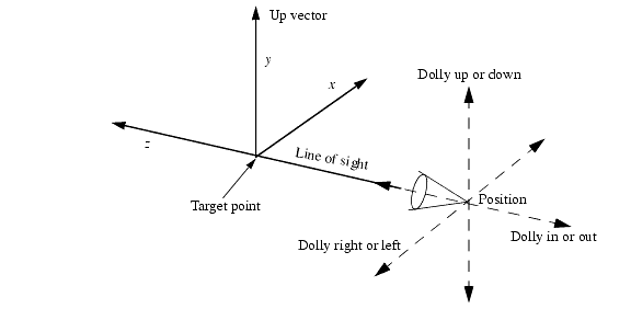
Dollying of the camera.
The Dolly_Camera command takes three floating-point arguments. The first argument is the amount to dolly to the right (or, if negative, left), the second argument is the amount to dolly up (or, if negative, down), and the third argument is the amount to dolly in toward the target (or, if negative, away from the target).
Dollying the camera does not change the width and height of the camera field or the up vector (although they are now relative to the new camera target).
Dolly versus Zoom
Dollying the camera forward and back and zooming the camera in and out might seem to have a similar effect on a view, but the effects are actually quite different. If you are using an orthographic projection, then dollying the camera will not make the objects in the scene get larger or smaller, because, in an orthographic view, the size of an object does not depend on that object’s distance from the camera. To make objects larger or smaller in an orthographic projection, you need to zoom the camera (zooming changes the camera field).
In a perspective projection, zooming the camera in and out will make the objects larger or smaller, but it will also change the perspective in the scene. Dollying the camera forward and back will make objects in the scene larger or smaller without changing perspective, but if there is an object close in front of the viewpoint, then dollying the camera forward might put that object behind the camera (or, even more disconcerting, put the camera inside of the object). Likewise, dollying the camera back might put an object that used to be behind the camera in front of it, blocking the view.
Orbit
Another useful command is Orbit_Camera. This command lets you view your scene from various angles. The name orbit indicates that this command acts as though the camera were a moon orbiting around the object that you wish to view (actually, around the camera target point). Orbiting the camera produces the same change in the view as would occur if you rotated the scene the opposite direction about the target point, as shown below.
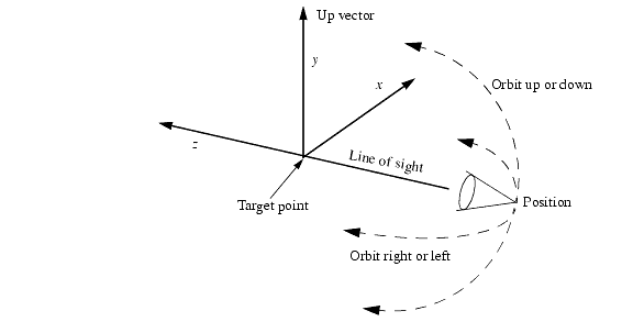
Orbiting of the camera.
The two arguments to Orbit_Camera are floating-point numbers. The first number is the amount to orbit around to the right (or, if negative, to the left). The second number is the amount to orbit up (or, if negative, down). If both arguments are non-zero, the left-right orbit is performed first.
For example, if we start with the default camera, then the command
HC_Orbit_Camera(90.0, 0.0);
…orbits the camera such that the camera is looking at the scene from the positive x axis.
If you orbit the camera up or down, the up vector is rotated by the same amount, so it remains perpendicular to the new line of sight. If you orbit the camera up 180 degrees (up and over the top), the scene will be upside down (with the up vector pointing in the negative y direction), but if you orbit the camera right 180 degrees, the scene will be right-side up (with no change to the up vector).
Each call to Orbit_Camera (like calls to all the camera-movement commands) works relative to the current camera position, so successive calls are cumulative. Two calls, each of which orbits the camera 10 degrees to the right, will orbit the camera a total of 20 degrees.
Pan
Imagine the camera positioned on a tripod. Without changing the position of the tripod, you can swivel the head of the tripod right and left, or up and down. This movement is called panning. Panning the camera changes the camera target, but leaves the camera position unchanged. In addition, if you pan up or down, the camera up vector is rotated an equivalent amount, so it remains perpendicular to the new line of sight.
The two arguments to Pan_Camera are the amount (in degrees) to pan to the right (or, if negative, to the left), and the amount to pan up (or, if negative, down). For example, if someone says “look, up in the sky, it’s a…”, you probably want the following command:
HC_Pan_Camera(0.0, 90.0);
If both an up-down pan and a right-left pan are specified, then the right-left pan is performed first.
Note that pan and orbit both rotate the camera, but Orbit_Camera rotates the camera about the target point and changes the camera position, whereas Pan_Camera rotates the camera about the camera position and changes the camera target.
Roll
The Roll_Camera command rotates the camera about the line of sight, leaving both the camera position and target unchanged. It is equivalent to rotating the up vector. A positive roll rotates the camera counter-clockwise, which makes the scene appear to rotate clockwise. Rolling the camera produces the same change to the view as would occur if you rotated the scene the opposite direction about the line of sight.
The following command causes the camera to stand on its head, turning the scene upside-down.
HC_Roll_Camera(180.0);
Calculating Scene Extents
The default HOOPS camera assumes that your scene lies between -1.0 and +1.0 on the x and y axes. In reality, of course, most scenes are not that cooperative. A scene might be much larger or even smaller, or it might not even lie at the origin. This section presents simple programs that will make it easy for you to set up a camera in your application.
For example, say that your scene contains objects that lie between -100 and +100. You could change the camera field, but then your camera field would be much larger (200 units) than the distance between the camera position and the camera target (which, by default, is 5 units). This situation will give you the equivalent of a very wide lens and consequently a very distorted perspective view (objects closer to the camera position will appear overly large).
To make this image look normal, you also need to move the camera position back (just like a photographer might move back when photographing a large scene). How far should you move the HOOPS camera? In the default camera, the camera field is 2 units wide and the camera position is 5 units from the target, so, if our new camera field is 200 units wide, then it stands to reason that our new camera position should be 500 units back. To view this scene, we would use the following commands:
    HC_Open_Segment("?Picture");
    HC_Set_Camera_Position(0.0, 0.0, -500.0);
    HC_Set_Camera_Field(200.0, 200.0);
    HC_Close_Segment();
These commands work if our scene is centered about the origin, but what if it is not? For example, what if our scene lies between 0 and 200 on the x axis? We could translate the scene until it is centered, but that would be cheating. Instead, we set a new camera target (in addition to a new camera position and camera field), as follows:
    HC_Open_Segment("?Picture");
    HC_Set_Camera_Target(100.0, 0.0, 0.0);
    HC_Set_Camera_Position(100.0, 0.0, -500.0);
    HC_Set_Camera_Field(200.0, 200.0);
    HC_Close_Segment();
Both the camera position and the camera target have been moved 100 units in the positive x direction; the camera no longer lies on the z axis, and it is not looking at the origin. Because both the camera position and target have been moved by the same amount, the new line of sight is parallel to the old line of sight (the z axis), but is translated 100 units in the positive x direction. Similarly, if the object were not centered on the y axis, we could change the y value of the camera position and target by changing the second argument to these two commands.
Because it is common to change the camera position, target, and field at the same time, HOOPS provides a single command to change all three. Instead of calculating and setting a new camera position, target, and field, we can use the Set_Camera_By_Volume command. Given the x and y range of a scene, this command sets up a reasonable view for you. For example, to view the scene just described, which lies between 0 and 200 on the x axis and -100 and +100 on the y axis, you would use the following commnd:
    HC_Open_Segment("?Picture");
    HC_Set_Camera_By_Volume("perspective", 0.0, 200.0, -100.0, 100.0);
    HC_Close_Segment();
The Set_Camera_By_Volume command also lets you set the projection.
Set_Camera_By_Volume always sets the line of sight parallel to the z axis, with the camera displaced in the negative z direction from the target, looking toward the x, y plane, and with the up vector pointing in the positive y direction. If you do not want these defaults, you can first call Set_Camera_By_Volume, and then orbit or roll the camera to the desired position.
As you should with the other camera-oriented commands, if you want the camera created by Set_Camera_By_Volume to apply to your entire scene, you should be careful to use this command on a segment such as “?Picture” or a driver instance segment.
Setting the Camera to a Bounding Volume
It is frequently necessary to calculate the screen-space (2D) or world-space (3D) extents of the scene. HOOPS/3dGS provides support for both, and can also return the extents of a portion of the scene-graph. The functions Compute_Circumcuboid and Compute_Circumsphere return the points of a cuboid/sphere that circumscribes the geometry within a segment (including it’s subsegments). The points denote a region in the current segment’s object-space, but the region takes into account any modelling matrices encountered in subsegments. This routine can be useful for positioning cameras in particular locations (to view a portion, or all of the scene). You can call Set_Heuristics to “[no] exclude bounding” to remove the current segment and its children from bounding box calculations.
The above functions do not honor visibility settings and will always return the extents based on looking at all objects located in the specified segment tree (with the exception of segments that are excluded via the “exclude bounding” heuristic). If it is desirable for visibility settings to be taken into account, you can use the ‘filter’ variants of the aforementioned functions. Namely, Filter_Circumsphere and Filter_Circumcuboid. These take an options string which denotes the visibility settings of interest.
HOOPS/3dGS also supports a 2D variant of the above functions. Compute_Screen_Extent determines an exact fit around a specific part of the segment tree. It returns a screen space box whose coordinates in HOOPS/3dGS window space. The box will be camera dependent and account for both visibility settings in the underlying segment tree as well as any text contained therein.
This code determines the extent of the geometry in the database tree under the “?Picture” segment using the Compute_Circumcuboid command, and sets an appropriate camera on “?Picture” to view it:
1   Point min, max;
2   HC_Open_Segment("?Picture");
3     // find the bounding box of the object
4     int success = HC_Compute_Circumcuboid(".", &min, &max);
5     if (!success) printf("no geometry in ?Picture");
6     // convert to world coordinates
7     HC_Compute_Coordinates(".", "object", &min, "world", &min);
8     HC_Compute_Coordinates(".", "object", &max, "world", &max);
9     // the conversion of object ->; world coordinates
10    // may have flipped the min and max points
11    if (min.x > max.x)
12     float tmp = min.x; min.x = max.x; max.x = tmp;
13    if (min.y > max.y)
14     float tmp = min.y; min.y = max.y; max.y = tmp;
15    HC_Set_Camera_By_Volume ("perspective", min.x, max.x, min.y, max.y);
16  HC_Close_Segment();
Setting of the camera to a bounding volume.
Line 1 defines two points, called min and max, that will be used to hold the min and max points of the bounding volume of the scene. Line 2 opens “?Picture” as the current segment. The bounding volume is retrieved in line 4 with the Compute_Circumcuboid command. This command always takes a segment name as an argument, so we use “.” to indicate that we want to know the bounding volume for the current segment (“?Picture”).
The bounding volume is always returned without regard to any transformations on the current segment, so, to take into account any transformations on “?Picture”, we need to transform the min and max points into world coordinates (note that, if we are absolutely sure that “?Picture” does not have any modeling transformations set on it, we can leave out lines 7 through 14). Lines 7 and 8 transform the min and max points from the object-coordinate system of the current segment into the world-coordinate system. Lines 11 through 14 make sure that min is still less than max after the transformation. Finally, line 15 sets up the camera to view the bounding volume of the scene.
Keeping Parts of the Camera Constant
The previous code ignored the current camera when it set up its camera. So regardless of what direction the old camera was facing, the new camera always viewed the scene from the negative z direction (facing toward positive z). Sometimes, that is not what you want. Sometimes, you want to keep some parts of the old camera, but want to modify the camera (slightly) to fit the scene into the output window.
For example, you might want to keep viewing the scene from the same angle. Your graphics application may let the user orbit and dolly the camera around to view the scene from any desired angle or position, but you also want to provide a command to fit the scene into the output window. Users would be disconcerted if they were viewing the scene from (for example) the positive y axis (from above), but when they pushed the button to fit the view to the scene, the view shifted abruptly such that they were viewing from the negative z axis. Instead, you would like to keep viewing from the positive y axis, but change other components of the camera to fit the view to the scene.
Alternatively, you might want to keep the same camera position, and to change the direction that the camera is facing. An example is an application that flies the camera around a scene during an animation, to look at the scene from all sides, but at the same time keeps the scene centered in the view.
We shall present two routines, one to solve each of these two problems. Both routines start with the current camera. The first routine dollies the camera (which keeps the line of sight parallel to the line of sight of the original camera) until the camera is looking at the center of the scene, and then dollies the camera (again) forward or back until the scene just fills the view. The second routine keeps the camera position the same, and pans until the camera is looking at the center of the scene, then dollies the camera forward or back until the scene fills the view.
The first routine works as follows:
- Find the centroid of the scene to be viewed.
- Preserving the angle of the current line-of-sight vector, dolly the camera such that the line of sight passes through the centroid of the scene. Do so by dollying the camera until it is positioned exactly at the center of the scene.
- Back off the position of the camera so that the distance to the target is 2.5 times the field width. In addition, constrain the position to lie along the line of sight. Do so by dollying the camera in the negative z direction (the dolly works in viewpoint space, and viewpoint z is the line of sight).
- Set the camera field width and height to be twice the length of the radius of the object’s bounding sphere.
The two arguments to the dolly_camera_to_object function are the name of the segment containing the camera (typically “?Picture”), and the name of the segment containing the scene (can also be “?Picture”).
void dolly_camera_to_object(char* camera_path, char* object_path)
{
// find the centroid of the scene
HPoint center(0, 0, 0);
float radius;
HC_Compute_Circumsphere(object_path, ¢er, &radius);
// find the current settings for the camera
HC_Open_Segment(camera_path);
HPoint position, target;
HC_Show_Net_Camera_Position(&position.x, &position.y, &position.z);
HC_Show_Net_Camera_Target(&target.x, &target.y, &target.z);
// dolly the camera to view the scene center
HC_Dolly_Camera(center.x - target.x, center.y - target.y, center.z - target.z);
// back off
HPoint view_axis(center.x - position.x, center.y - position.y, center.z - position.z);
double distance = HC_Compute_Vector_Length(&view_axis);
// compute distance to back out the camera
double back_up = 2.5 * (2.0 * radius) - distance;
// the dolly moves the target as well
HC_Dolly_Camera(0.0, 0.0, -back_up);
// set the target back to the object centroid
HC_Set_Camera_Target(center.x, center.y, center.z);
// set the camera field width and height
if (radius == 0.0)
radius = 1.0;
HC_Set_Camera_Field(2 * radius, 2 * radius);
HC_Close_Segment();
}
Dollying the camera to fit the scene in its view.
The following code is simpler:
- Find the centroid of the scene to be viewed.
- Set the camera target to the scene’s centroid; this action logically is a pan.
- Set the camera field width and height to be twice the length of the radius of the object’s bounding sphere.
- Adjust the position of the camera such that the distance to the target is 2.5 times the field width, by dollying the camera in the negative z direction.
void pan_camera_to_object(char* camera_path, char* object_path)
{
// find the centroid of the scene
HPoint center;
float radius;
HC_Compute_Circumsphere(object_path, ¢er, &radius);
HC_Open_Segment(camera_path);
// find the current settings for the camera
HPoint position;
HC_Show_Net_Camera_Position(&position.x, &position.y, &position.z);
// set the camera target to the scene's centroid
HC_Set_Camera_Target(center.x, center.y, center.z);
// set the camera field width and height
if (radius == 0.0)
radius = 1.0;
HC_Set_Camera_Field(2 * radius, 2 * radius);
// back off
HPoint view_axis(center.x - position.x, center.y - position.y, center.z - position.z);
double distance = HC_Compute_Vector_Length(&view_axis);
// compute distance to back out the camera
double back_up = 2.5 * (2.0 * radius) - distance;
// the dolly moves the target as well
HC_Dolly_Camera(0.0, 0.0, -back_up);
// put it back at the center
HC_Set_Camera_Target(center.x, center.y, center.z);
HC_Close_Segment();
}
Panning the camera to fit a scene in its view.
Creation of a New Camera
As mentioned previously, if you set a camera attribute on a segment that does not already have a camera attribute set on it, HOOPS will create a new camera for you, and will set it on that segment. Most of the time, when you are just modifying your scene’s camera, you will be executing camera-oriented commands on “?Picture”. There are a few times, however, when you might want to have more than one camera in a scene. You already know how to do that - simply call any camera-oriented command on a segment that does not already have the camera attribute set on it, and HOOPS will create a new camera - but what does it mean to have more than one camera in a scene?
The main reason to have more than one camera in a scene is if you want different parts of a scene to be viewed with different cameras. For example, you might want to be able to orbit the main camera to view an object from different directions, while using a separate camera to view a background pattern for your scene from a fixed position. Or you might create a scene that contains two objects, and you want one object to be viewed in perspective and the other object to be viewed orthographically.
As we discussed in the beginning of this section, cameras are inherited just like any attribute. In this example, a camera has been set on segment B. Everything in the scene will be viewed by the default camera except for those objects underneath (or in) segment B:
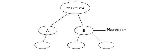
A scene with more than one camera.
You can find out the value of the camera that will be used to view the geometry in a segment by using Show_Net_Camera (or you can show the net value of any of the camera’s components, for example, using Show_Net_Camera_Field).
Note that simply inserting a camera does not cause anything to be sent to the display screen; that is the function of a driver. Any cameras that you create must still be under some driver segment (such as “?Picture”) to be displayed. The camera attribute simply defines the viewing transformation that will be used by the driver to view the geometry. A good way to think of the difference between a camera and a driver is that a camera maps a scene into a window, whereas a driver instance maps a top-level window onto a display device.
You can also use multiple cameras to create multiple views of the same object. You normally use multiple views only when you have multiple windows, each with its own camera. Viewing the same object multiple times logically requires including the object more than once in the scene (for example, using Include_Segment).
Oblique Projections
So far, we have talked about only orthographic and perspective projections. HOOPS also provides two oblique projections: oblique perspective and oblique orthographic. Oblique projections involving skewing.
Oblique orthographic - An orthographic projection is typically used in drafting applications so that objects do not get smaller as they get farther away, and so that parallel lines remain parallel. Unfortunately, a regular orthographic projection can cause some lines to be hidden. As shown in the image below, viewing a cube straight on in an orthographic view causes it to look like a square.
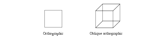
Orthographic and oblique orthographic views of a cube.
In an oblique orthographic view, the x and y coordinates are skewed depending on the z coordinate. For example, a typical oblique orthographic view moves objects up and to the right (but does not make them smaller) as they get farther away. We can thus see the sides of the cube, even though we are still viewing it straight on. See the documentation for Set_Camera_Projection for more information.
Oblique perspective - An oblique-perspective projection is useful when the target plane of a perspective projection is not perpendicular to the line of sight. There are a few (albeit specialized) situations where this kind of projection can be useful.
For example, consider a graphics system with three display monitors arranged side by side to display a panoramic view of a single scene. Logically, the three monitors are displaying a single view, but physically we need to create three separate views, one for each monitor. For the two side monitors, the screen is not perpendicular to the line of sight, so we must use a target plane (which is always parallel to the screen) that is not perpendicular to the line of sight. This image shows the situation viewed from above (looking down the y axis):
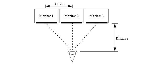
Use of oblique perspective with multiple monitors.
To make this setup work, we rotate the target plane about the y axis for the side views, using an oblique-perspective projection.
To determine the proper angle to rotate the target plane for each monitor, we take the offset from the camera target to the center of the monitor, divided by the distance from the viewpoint to the (entire) target plane, and take the arc tangent of the result. For example, if we are using a default camera for monitor 2, then monitor 1 is offset 2.0 units, and the distance from the viewpoint to the target plane is (the default) 5.0 units, which gives us arctan(2.0 / 5.0) = 21.8 degrees. For the camera corresponding to monitor 1, we issue the following command:
HC_Set_Camera_Projection("oblique perspective = 21.8");
The camera for monitor 3 will have its target plane rotated -21.8 degrees.
The same trick may be useful even if you are not using multiple monitors. For example, consider a flight simulator used for training airplane pilots. Such simulators display the view that the pilot would see out of a window in a monitor positioned where the window would be. Often, these windows are not perpendicular to the pilot’s line of sight, so an oblique-perspective view is required.
Another use for oblique-perspective views is for creating stereo images. To create a stereo image, we need to create two views of an object: one from the perspective of each eye. We already know how to create two views of the same object using two cameras. We offset each camera slightly left or right to approximate the position of each eye; however, then the line of sight for each eye is no longer perpendicular to the target. Here we showthe situation viewed from above.
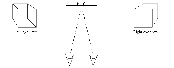
Use of oblique perspective for a stereo view.
We would rotate the target plane slightly for each eye with an oblique-perspective projection. However, it is not necessary for us to manually setup oblique perspective views to create a stereo image because HOOPS/3dGS provides built-in support for stereo viewing.
Stretched Projections and 2D-Scenes
Previously, we explained how HOOPS keeps the aspect ratio of a scene constant, even when we change the aspect ratio of the window. HOOPS keeps the aspect ratio constant by adding extra space to the camera field either on the sides or on the top and bottom. In some cases, however, we might want the camera field to fill the output window exactly, even if that means changing the aspect ratio of the scene. In HOOPS, we can fill the output window exactly with a stretched projection. A stretched projection stretches the scene to fit into the output window.
This program draws a circle in the middle of the screen, and demonstrates stretched projections.
    HC_Open_Segment("?Picture");
    HC_Set_Driver_Options("subscreen stretching");
    HC_Open_Segment("border");
    HC_Set_Camera_Projection("stretched");
    Point border[4] = {{-1.0, -1.0, 0.0}, {1.0, -1.0, 0.0}, {1.0, 1.0, 0.0}, {-1.0, 1.0, 0.0}};
    HC_Insert_Polygon(4, border);
    HC_Set_Visibility("faces=off, edges=on"); // only edges are drawn
    HC_Set_Edge_Weight(50.0);
    HC_Close_Segment(); // border segment
    HC_Close_Segment(); // ?Picture
Setting a stretched projection
Initially, this code draws the circle using the default (perspective) projection, and then pauses. At this point, you could try resizing the output window, changing its aspect ratio. (The command on line 2 allows you to change the aspect ratio by enabling subscreen stretching. Since this is a HOOPS-created window, subscreen stretching is supported by HOOPS) As you resize the output window (and change its aspect ratio), the circle remains circular, as shown here:
Regular projection - circle stays circular.
After you click the mouse inside the HOOPS output window, the program changes the projection to “stretched” and pauses again. If you now resize the output window, then the aspect ratio of the scene will change as you change the aspect ratio of the window. Thus, the circle will not remain circular, as shown here:
Stretched projection - circle stretches to match window.
With a stretched projection, the scene stretches to fit the output window. Why would we want that to happen? Do we not want our circles to remain circular and our squares to remain square?
One case where we would use a stretched projection is to draw a border around the inside of a window. The following code draws a thick black border by drawing a black edge around the inside of the window:
HC_Open_Segment("?Picture");
HC_Set_Driver_Options("subscreen stretching");
HC_Open_Segment("border");
  HC_Set_Camera_Projection("stretched");
  Point border[4] = {
        {-1.0, -1.0, 0.0},
        { 1.0, -1.0, 0.0},
        { 1.0,  1.0, 0.0},
        {-1.0,  1.0, 0.0}
  };
 HC_Insert_Polygon(4, border);
 HC_Set_Visibility("faces=off, edges=on");
 HC_Set_Edge_Weight(50.0);
HC_Close_Segment();     // border
HC_Close_Segment();    // ?Picture
HC_Pause();
A window border using a stretched projection.
The segment named “border” (opened on line 3) contains a polygon (lines 5 through 11) that is exactly the same size as the camera frame. Since this segment has a stretched projection (set on line 4), this polygon will fit exactly inside the output window. Only the edges of the polygon are drawn (line 12), with an edge weight of 50 (line 13), to give a thick border.
Note that line 4 - which sets the camera projection to “stretched” - creates a new camera in the segment named “border” (not in “?Picture”). Thus, only the geometry inside “border” will be drawn with a stretched projection; any objects in the “?Picture” segment, but not in “border”, will be drawn with a non-stretched projection. When the user resizes the window for this scene, the border will change aspect ratio to match the window, but the circle will keep a one-to-one aspect ratio and will remain circular, as shown:
The border stretches, but the circle does not.
There are other cases where we might want to use a stretched projection, but they are mainly for 2D graphics.
Another case where stretched projections are useful is when we want to place an object in a specific position of the output window, even if the output window is resized. For example, to place an object (such as a user-interface gadget) in the upper-right corner of the window, we can position it at *x* = 1, *y* = 1, but then it will appear in the upper-right corner only if the output window is square. By using a stretched projection, we can place objects accurately regardless of the aspect ratio of the output window. Another such use would be to place a toolbar along one of the sides of the window. The toolbar itself could then use a non-stretched projection, so that the tools (buttons and sliders) would not stretch.
Camera Setup Guidelines
How you set up the camera in a scene can significantly affect the visual quality of the rendered result. To maximize visual quality and reduce artifacts like edge stitching and shinethrough, we recommend that you follow the camera set up guidelines outlined in this section.
When you set up your camera, the target should be at the center of the model’s bounding box. The distance from the camera position to the camera target should be 2.5 times the field width. This 2.5:1 camera ratio maximizes the z-buffer resolution around the camera target thus reducing the occurrence of edge stitching or shinethrough. It also provides a commonly accepted level of foreshortening for perspective projections.
This general camera set up should be maintained even when zooming in, out, or to the extents of a specific object. For example, when zooming in, you should NOT actually zoom the camera because it effectively modifies the camera field thus changing the 2.5:1 ratio that you want to maintain. Instead, you can create the effect of zooming by dollying the camera. Specifically, you should reset the camera target to the middle of the object that you wish to view, modify the field as desired, and then move the camera position forward or back to maintain the 2.5:1 camera ratio.
If you deliberately want to set up an extreme field of view where the camera ratio is 5:1 or higher, additional steps are required to preserve the visual integrity of your scene. Although HOOPS automatically sets the near clip plane to the front most object in the scene to maximize the z-buffer resolution, there are situations where this is not effective. For instance, if you have zoomed into a small part in a complex model, there maybe other parts that are not visible in the view frustum but whose bounding box is still closer to the camera position or possibly behind it. In the case, the HOOPS automatic near plane adjustment will not be effective. You need to manually reset the near clip plane so that it is closer to the bounding boxes of the objects being viewed.
Even when the HOOPS automatic near plane adjustment does increase the z-buffer resolution significantly, it cannot remove all the potential edge stitching and edge shinethrough at extreme fields of view. In these cases, you may need to modify the “face displacement” option in HC_Set_Rendering_Options. In addition to tweaking the “face displacement” value, you can also call Set_Rendering_Options and set the “vertex displacement”. These two set in conjunction with one another can be used to fine tune the visual quality of your scene reducing edge shinethrough and stitching.
Changing the Camera Near Plane
By default, Visualize will automatically adjust the near clipping plane to be as close to the camera target as possible, which should generally result in good usage of z-precision. In special circumstances, you may want to favor precision of certain objects at the expense of clipping other objects, and this can be achieved by manually setting the camera’s near clipping plane to a positive value (this will disable the default “auto-adjust” behavior).
The camera near limit can be set in two ways:
Define_System_Options ("camera near limit = [x]");
…or…
HC_Set_Camera_Near_Limit(near_limit_value);
NOTE: The behavior of Set_Camera_Near_Limit can differ slightly between 3D drivers and software drivers. Please see the reference manual for details.
Masking Camera Transforms
It may be useful in certain cases to have HOOPS/3dGS ignore rotations, scales, or translations that are the result of a modification to the camera. An example would be an axis triad that shows the user the current camera orientation. As the camera is zoomed or panned (scaled and translated), you wouldn’t want the axis triad to scale or translate (only rotate). The “mask transform” in rendering options allows you to do this:
HC_Set_Rendering_Options("mask transform = (camera=[rotation/scale/translation])");
HOOPS/3dGS can also ignore rotation, scale, and translations that are the result of a modelling matrix. This feature is discussed here.
Stereo Viewing
Stereo viewing is discussed in this section.

