Meshes
A mesh is similar to a shell in that it is a collection of faces, but a mesh is simpler than a shell, and that simplicity allows it to be stored and displayed more efficiently. A mesh is like a rectangular wire screen mesh - it can be bent into an arbitrary curved surface, but it is still topologically a quadrilateral (it has four edges).
A mesh is defined by a 2D array of points. Here, the terms ‘rows’ and ‘columns’ refer to the rows and columns of points in the mesh, not the faces. For example a mesh with one square face (two triangles) would have 2 rows and 2 columns.
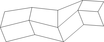
3 by 5 mesh containing eight faces.
In the figure above, we see a 3 by 5 mesh (3 rows by 5 columns, for a total of 15 points).This mesh would be defined as follows:
HC_Insert_Mesh(3, 5, point_array);
…where point_array is an array of 15 points, specified row by row. Because the way in which the quadrilaterals are connected is fixed, there is no need for a face list (as there is in a shell).
The points in the mesh are connected into quadrilaterals. The quadrilaterals in a mesh are often not planar (as required by the renderer), so they are further subdivided in half into triangles. The resulting bands of triangles are called triangle strips, or just tri-strips.
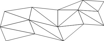
Mesh divided into tri-strips.
It is common for high-end 3D graphics hardware to be optimized to display tri-strips, so using meshes is an especially fast way to display 3D surfaces.
Mesh Attributes
The attributes that apply to meshes are almost identical to those that apply to shells. For more information, refer to our section on shell attribues on shell attributes.
One difference between shells and meshes is that meshes have one additional option for the visibility of edges - it is possible to turn on and off the visibility of the mesh-quad edges separately. The mesh-quad edges are all the edges in the mesh except the diagonal ones. Normally, when edges are visible, all edges are drawn, including the diagonal edges. To turn off the visibility of diagonal edges, we turn off the visibility of edges, and then turn back on the visibility of mesh quads.
HC_Set_Visibility("edges=(off, mesh quads=on)");
This operation is so common that there is an abbreviation:
HC_Set_Visibility("edges=mesh quads only");
With the visibility set this way, our mesh looks like this:

Mesh with only mesh quads visible.
You can also set, unset, and show attributes on individual parts (vertices, edges, and faces) of a mesh, just like you can those of a shell. The vertices are numbered as they are arranged in the point list. To identify vertex number, use the following calculation. For a rows x columns mesh with a vertex at (r, c), the “vertex number” is just r * columns + c. Note that we begin counting at 0. Soif your vertex is in the first row, then r is equal to 0. If your vertex is in the fourth column, then c is equal to 3. The following image shows the vertices as they would be numbered for Open_Vertex (and as they are arranged in the point list).
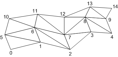
The vertices in a mesh.
Because a mesh has no face list, we need a scheme to number the faces. Here is how we do it. For a rows x columns mesh, the triangle between (r, c), (r+1, c), and (r, c+1) is numbered 2*(r * (columns - 1) + c). The triangle between (r + 1, c + 1), (r, c + 1), and (r + 1, c)—is numbered 2*(r * (columns - 1) + c)+1. Note that we begin counting at 0. So the firstrow would make r = 0 in the calculation.
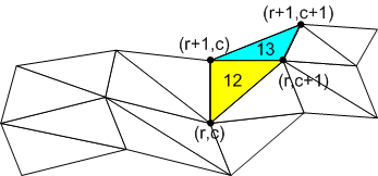
Calculating face numbers in a mesh.
Here, we find the face number of the yellow triangle by performing the calculation 2*(r*(columns-1)+c) where r = 1, c = 2 and columns = 5. Therefore, the yellow triangle’s face number is 12. For the blue triangle which is between (r + 1, c + 1), (r , c + 1) and (r + 1, c), we perform the calculation 2*(r * (columns - 1) + c)+1 to find that it’s face number is 13. To access the attributes of the blue triangle, we call Open_Face passing 13 for the ID.
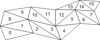
The numbered faces in a mesh.

