Environment and Bump Mapping
Environment Mapping
The idea behind environment mapping is to render an object as if it were perfectly reflective, so the colors on its surface are those reflected to the eye from its surroundings. In other words, if you look at a perfectly polished, perfectly reflective silver object in a room, you see the walls, floor, and other objects in the room reflected off the silver object. To approximate an environment texture map, developers can use an image taken from an extremely wide-angle lens. “Environment mapping” is enabled via the following steps:
The face color sub-options “environment” and “mirror” must be set. For example:
HC_Set_Color("faces=(diffuse=white, environment=metal,mirror=grey)")
The user must define a texture (or named image – see this page) to be used as the environment, and a color to be used as the mirror value. The grey scale of the mirror value (average of r, g, b) determines the relative weight of the image vs the underlying diffuse color of the material. As one might expect, a value of 1.0 means “perfectly reflective”, with the result that the diffuse color makes no contribution at all.
Environment maps can be either a regular 2-D texture or a cube map. Using a ‘cube map’ instead of a 2-D texture for the environment map will provide a more accurate visual result. In the 2-D texture map case, it is assumed that the texture has a spherical texture layout, which can be thought of as a set of distorted polar coordinates. The layout is modified by setting the “layout” option in
Define_Texture.The “parameterization source” sub-option of
Define_Texturemust be set to “reflection vector” (ordinary texture mapping assumes “parameterization source = uv”).
This image was created using environment mapping to depict a lake side scene being reflected on the surface of a blue vase:
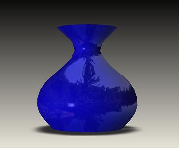
Environment mapping example
The standard HOOPS distribution contains a good demonstration program to show a few of the settings that are available (see env.c).
Zebra Striping
Zebra-striping is a diagnostic shading technique used to help visualize surface curvature, and is typically implemented via a specific application of Environment Mapping, in which stripes or some other image is reflected by the part in realtime as you rotate pan zoom. The fact that zebra stripes or environment maps move across the surface while you rotate the part makes them more useful for finding surface irregularities. The behavior of the stripes can indicate various degrees of surface continuity. G0 portions of a surface, which are position-only continuous, will show disjointed stripes; G1 surfaces, which are tangency continuous, show stripes that may be continuous, but have kinks; and G2 surfaces, which are tangency and curvature continuous, show smoothly flowing stripes.
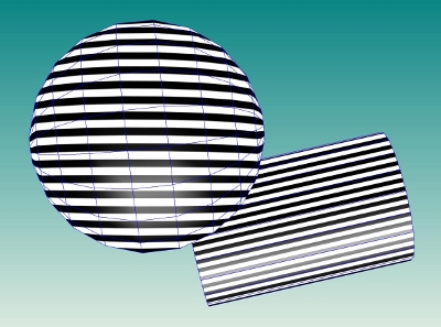
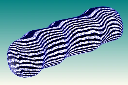
Zebra-striping is accomplished in HOOPS by applying a texture with colored “bands” as an environment map to an object, and using “parameterization source = reflection vector” in the texture definition of Define_Texture. The following images show a few examples of zebra-striping:
|
|
Zebra Striping examples
It is important to remember that HOOPS shells and meshes are tessellated approximations of surfaces. Therefore, the quality and density of this tessellation will have an impact on how effectively and accurately the zebra-stripes convey continuity of the original surface. For example, if the original B-REP surface was smooth at a particular location, but the surface tessellation contained major triangle-discontinuities (i.e. duplicate points at adjacent facets) and surface-derived ‘smooth’ vertex normals were not provided to HOOPS, then the zebra stripes will be disjointed and give a misleading depiction of the original surface’s curvature. To help ensure that the zebra-stripes are generally accurate, any surface-derived vertex normals produced by your solid modeller or surface-generation tools should be explicitly set on the HOOPS shells.
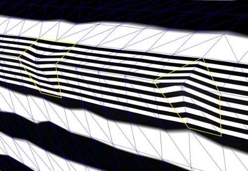
Misleading zebra stripes. In the absence of explicit normals HOOPS will calculate normals based on the shell triangulation
A sample zebra-stripe image called /datasets/textures/environment/zebra.jpg is included with the datasets package (available from the Tech Soft 3D Developer Zone) at <hoops_install_dir>\datasets\textures\environment.
Bump Mapping
HOOPS Visualize supports bump mapping in the OpenGL2 and Direct3D drivers. This allows a surface to have a custom lighting calculation per pixel based on a provided bump map, which contains a normal per pixel. It is enabled by setting the “bump” color channel in Set_Color:
HC_Set_Color("bump = <texture name>");
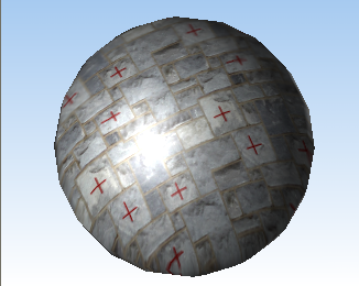
|
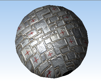
|
A sphere on the left with a stone wall texture applied to it while the sphere on the right has an additional bump map applied to it.

