Rendering
Display Lists
A display list is a set of drawing commands that are stored in a video card’s memory. It can be beneficial to cache commands in a display list if you plan to draw the same geometry repeatedly, which is typically the most common use case with HOOPS’ purpose as a retained-mode graphics system. HOOPS/3dGS supports display lists for OpenGL, OpenGL2, and DX11. This capability can be accessed via the “display lists” option in Set_Rendering_Options. This option has the following possible values: geometry, segment and off. Note that the default value is off. Additionally, to use display lists under the OpenGL driver, you must first define the “polygon handedness” option in Set_Heuristics on the model as described in detail in this section of the Programming Guide.
Segment Level
When the “display lists” option is set to “segment”, HOOPS creates a single display list for all the geometry in that segment. This option is typically the best setting to use, assuming that your scene-graph is reasonably organized by attributes, and each segment contains hundreds, or perhaps even thousands, of graphical primitives. The “segment” option does have some performance implications if your geometry is changing frequently over the course of many updates (during rotating, panning, zooming, etc…) Whenever a piece of geometry changes in a segment that has the “segment” display-list setting, the entire segment-level display list needs to be regenerated. This requires some amount of processing time which can cause the next HOOPS Update to take longer. There are a few application use cases where some intelligent logic can help minimize any unacceptable delay caused by segment-level display lists recreation:
- Highlighting: Highlighting typically involves changing the attributes (color/line-style, etc..) of primitives. Therefore, if you select By_Area on a few thousand polylines that are grouped nicely by attribute in segments with the “segment” display-list setting, one approach is to move them out of those segments into a temporary ‘highlight’ segment that contains the highlighting attributes. However, there is a much more efficient way called ‘quickmoves reference’ highlighting, which consists of creating a ‘reference’ to the highlighted entities within another segment that contains the “quickmoves” Heuristic setting. This causes the geometry to be quickly ‘overdrawn’ using the highlighting attributes, and can also be ‘undrawn’ without having to touch the original geometry (thus the “segment” display-lists are not invalidated/rebuilt), and without having to redraw the entire scene. Refer to the highlighting section and the scene interaction section for more information on quickmoves-reference highlighting, and quickmoves in general.
- Realtime/continual editing: Let’s say a segment contains many shells and has the “segment” display-lists setting to maximize performance, and you wish to perform some realtime edits to one, or a few shells (i.e. dynamically loft a surface). A reasonable approach would be to move the shells into another segment, and then perform the edits on the moved shells. (Note that the new segment should NOT have the display-list setting at all, since you are changing the geometry every update.) There will be a small hit due to moving the shells out, thus causing the segment-level display list to get invalidated/rebuilt. But the continual editing operation will be much faster with this overall approach.
- Animations: Typically only a small subset of items in a scene-graph are animating. Perhaps they are moving around, or the geometry itself could be changing. Geometry being animated should ideally reside in segments that do not have the “segment” display list setting.
To facilitate the creation of the segment level display lists, you can call Control_Update with the “compile only” option. This option tells HOOPS, on the next update, to skip all drawing. Instead, it will do nothing but assemble draw information. Such updates will generally be faster to process, and depending on the data and platform can sometimes be orders of magnitude faster.
    HC_Open_Segment(".");
    HC_Set_Rendering_Options("display lists = segment");
    HC_Control_Update("/", "compile only");
    HC_Close_Segment();
Using the “compile only” option when calling Control_Update can also help you twofold if you additionally have “static model” enabled. However, if this option does not improve performance to a reasonable degree, you might choose to set the display lists option to “geometry”.
Geometry Level
When the “display lists” option is set to “geometry” (or its synonym, “on”), HOOPS generates a single display list for each individual shell within a segment. So, when a shell is modified, only the display list for that shell needs to be regenerated. No other display list in that segment is affected. Note that if you have numerous primitives in each segment, the rendering performance will not be nearly as efficient as the “segment” option.
Video Memory Usage
When you use display lists, you are trading video memory for performance. To prevent problems related to low video memory, HOOPS/3dGS automatically monitors the amount of memory it uses and only creates display lists when video memory is available. A HOOPS system option can also be used to achieve this programmatically via the “video memory limit” option in Define_System_Options. This option allows you to cap the amount of video memory used by display lists.
Culling
The “culling” heuristic when used in conjunction with timed updates can be a powerful way to to maintain a constant framerate while still preserving the visual integrity of your scene. To leverage this feature of HOOPS Visualize, ensure that you are using the Update_Display_Timed function to control exactly how long Visualize spends on an update. Then use the “culling” heuristic to determine what is drawn on the screen and in what order.
Begin by setting “maximum extent” sub-option which tells HOOPS what is important in your scene based on screen size. When “maximum extent” is set on a segment, HOOPS Visualize uses this value to create a bounding box. Then, at update time, it compares all the objects in the given segment, including objects in the sub-tree, to this bounding box. If an object’s screen dimensions are within the bounding box, it will not be drawn. The following sample code below shows how to set the “maximum extent”.
HC_Set_Heuristics("culling = (maximum extent = 10)");
Once you have set the “maximum extent”, you can additionally employ the “maximum extent mode” for more refined control of the drawing process. This sub-option tells HOOPS Visualize how to manage the objects that do not meet the culling threshold. The most useful “maximum extent mode” for preserving visual integrity is “defer”. This mode tells HOOPS Visualize to defer drawing culled objects until the end of an update. At that point, geometry is placed in a fixed number of equal-sized buckets from large to small. Then, they are drawn in that order.
The defer “maximum extent mode” with the “maximum extent” can be used effectively along with timed update to achieve a constant frame rate. The application end-user will experience the ease of manipulating the model in a scene without any lag in performance or loss of visual integrity. However, some flickering may occur as HOOPS Visualize transitions from one update cycle to another. The sample code below shows how to put this feature into place.
    HC_Open_Segment("MyModel");
    HC_Set_Heuristics("culling = (maximum extent = 10)");
    HC_Set_Heuristics("culling = (maximum extent mode = defer)");
    HC_Close_Segment();
    HC_Update_Display_Timed(0.01);
There are other “maximum extent mode” options including none, dot and bounding. “Maximum extent mode” can still be used effectively when updates are not timed. However, the defer mode is not considered the best choice in this case. When updates are not timed, the “none” option gives you the best performance followed by “dot” and then “bounding”.
Another option to use in conjunction with “maximum extent” is “hard extent”. Unlike maximum extent, objects that fall under the hard extent threshold will not be put into a deferred list. In fact, they will not be drawn regardless of how much time may be left in the update. This option effectively creates a concrete lower bound in the scene preventing HOOPS from possibly spending a significant amount of time drawing objects that may be barely discernible. Since hard extent operates independently of maximum extent, we recommend that you set hard extent to a very small value such as one pixel while maximum extent might be five pixels.
View Frustum
Another “culling heuristic” is the ‘view frustum’ setting which means that HOOPS/3dGS does a bounding box check for each segment and shell/mesh primitive to see if the segment/primitive can be viewed by the current camera or lies within the selection region before trying to draw or select it. This is a common culling technique and is on by default; it should only be disabled for debugging purposes. The following code snippet shows how to set this sub-option.
HC_Set_Heuristics("culling = view frustum");
Vector and Vector Tolerance
The “culling heuristic” allows you to set a culling vector and tolerance for a given segment. HOOPS determines if the segment should be drawn by finding the angular difference between the culling vector and the view vector. If the difference is less than the tolerance angle, then HOOPS terminates the tree walk at that segment and it will not be drawn. If you organize your segment tree spatially by faces, then setting these two options could improve the rendering performance significantly.
Transparency
Transparency is reviewed in detail in the transparency section. The primary performance consideration relates to the choice of using the ‘z-sort’ style (default) or the ‘depth peeling’ style for hidden surface removal algorithm:
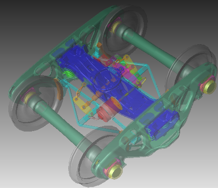
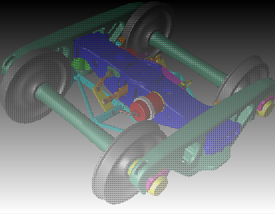
Z-sort provides a fairly accurate result regardless of how many layers of transparent geometry are in the scene, but will steadily reduce performance as the amount of transparent geometry increases. This is the case because the z-sort algorithm breaks every shell apart into each of its triangles and then sorts all of those. A faster but less accurate alternative is to sort based on the center point of each tri-strip within a shell. For a high quality rendering, we recommend that you set the transparency sub-option z-sort options to “nice” which uses the more accurate but expensive algorithm. For situations which require a shorter rendering time, we suggest you choose the “fast” z-sort option. To reduce visual artifacts when “fast” is set, we advise you to turn “backplane culling” on.
|
|
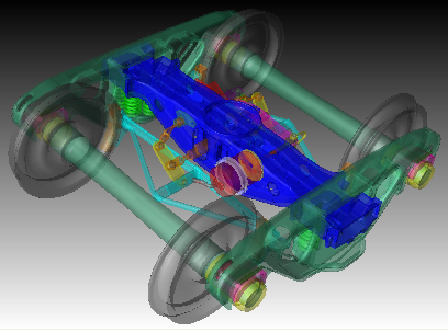
A model rendered with transparency z-sort option set to nice on the left and z-sort options set to fast on the right.
Depth peeling incurs a bit more overhead where there is only a small amount of transparent geometry, but will run significantly faster than z-sort for larger amounts of transparent geometry with the ‘depth peeling options = (layers = 1)’ setting. It will run at nearly the same speed as if there was no transparency in the scene. However, peeling away only the front most layer has the inherent downside that you will not see accurate transparency for additional transparent layers. If you wanted to see through 2 overlapping transparent objects to view opaque object behind them, the 2nd transparent object would not be drawn transparent. In these cases, it would be advisable to set layers to a value greater than one.
|
|
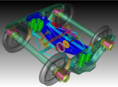
A model rendered with depth peeling set and “layers = 1” on the left and “layers = 2” on the right.
The performance crossover point for z-sort vs 1-layer depth peeling depends on the speed of the CPU and amount of transparent geometry. Developers should experiment with the 2 approaches, testing typical models, and then make a decision based on the subjective balance of accuracy vs performance. We encourage developers to begin with depth peeling and go from there.
However, if you have a situation where you want to forego high visual quality for the sake of performance, HOOPS/3DGS offers the “transparency style option” in Set_Rendering_Options called screen door.
This pseudo-algorithm can be used as a shortcut for blending. When this option is selected, only a fraction of the pixels of the transparent object will be drawn, effectively allowing the user to see through the transparent object.
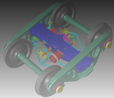
A model rendered with the screen door option set.
Quickmoves
Quickmoves are reviewed in detail here. The key performance takeaway include the following:
- Quickmoves should only be used in cases where a relatively small amount of geometry is being modified (edited, moved, etc..) The most basic example is temporary selection box or set of geometry ‘handles’.
- Developers should confirm that rendering performance is indicative of proper quickmoves usage. A way to confirm that quickmoves is working correctly is that when only quickmoves geometry is changing from one update to the next, ALL that should be redrawn is the quickmoved geometry. Thus the redraw should essentially be instantaneous. If there is any noticeable delay when only quickmoved geometry is changing from update to update, it means that something else has occurred in the scene-graph which is triggering a full scene redraw. In this event, you should contact support for troubleshooting assistance.
Maximizing Rendering Quality
A quality rendering result is essential to a positive end-user experience. The two most common problems that arise are edge shinethrough and edge stitching. When edges or lines either show up when they shouldn’t or stitch into the associated faces, this gives an unpleasant result.
Shell-Edge and Shell-Coincident Lines
This refers to a shell’s set of implicit edges or to a set of polylines whose definition points are a precise subset of a corresponding shell’s definition points. HOOPS Visualize performs a variety of automatic adjustment and mappings to minimize or remove these artifacts but there are still are additional steps that the developer must take. Perhaps the most important one is ensuring that the HOOPS camera is setup with reasonable values and kept that way. HOOPS Visualize has a set of camera setup guidelines which addresses this problem.
Extraneous Lines
There is a separate class of rendering artifacts that can arise when lines or polylines are inserted in the scene and are intended to “drape” on top of the corresponding shells but where the line or polyline definition points are not equal to shell definition points. In these situations, there is nothing HOOPS Visualize can automatically do to reduce or remove this artifact. If polyline points are not perfectly coincident with shell-vertices, there is no guarantee as to whether the polyline, shell facets or pieces of the polyline will be visible.
Highlighting
Highlighting is often necessary to provide feedback based on user input. But it can be an expensive operation because it can trigger a full redraw if your scene is set up inefficiently. However, there are several general highlighting strategies that can be employed to reduce the time Visualize needs to complete the highlighting operation.
- Use a defined highlight instead of just changing the color of geometry directly. Highlighting can be applied using any style defined in a style segment, but should be kept simple if you are conecerned about rendering speed.
- Restrict the use of the “In place” overlay method to those instances in which it is truly necessary.
- Because drawing highlights inherently increases drawing complexity, it is beneficial to keep a list of highlighted objects and un-highlight them as soon as possible. This method is favored over asking Visualize for which objects are highlighted through a highlight search since searching the scene graph for highlighted objects and then parsing the results is time intensive for large models.
- Keep track of which keys are highlighted and do not highlight them if they are already highlighted.
- Keep in mind that the more geometry is highlighted, the more performance will suffer, and this is especially true of complex models.
- Triggering highlights on mouse move callbacks is expensive because Visualize must process so many of them. Additionally, once the mouse moves off of the object, an “unhighlight” must be performed. Furthermore, if the highlight style contains transparency, the whole scene must be redrawn for each operation. If you must go thus route, keep your highlight style as simple as possible.

