Cylinders
Cylinders have a smaller memory footprint and can be rendered more quickly than shells. These two features can create many advantages for developers who have models that lend themselves to cylindrical representations.
In HOOPS, cylinders are defined as two circles, known as end caps, connected to one another to form a tube. To create a cylinder in the HOOPS database, use Insert_Cylinder. This function accepts two points, indicating the center points of the end caps, a radius and an options string. The options string is used to determine if either of the end caps will be rendered. The following sample code shows a cylinder with a 0.05 radius inserted into the database with options set to “none” indicating that neither end cap wil be drawn.
    float p1[3] = {0, 0, 0};
    float p2[3] = {0, 0, 1};

    HC_Insert_Cylinder(p1, p2, 0.05, "none");
Edge and face visibility affect cylinders just like they affect shells. When edges are visible, the cylinder is rendered with two edges connecting the two circles like struts. The edges around the end caps are considered hard edges while the struts are silhouette edges under the right viewing angles. When markers are visible, there will be one marker at the center of each end cap.
Polycylinders
Polycylinders are a sequence of connected cylinders defined by a collection of vertices and their associated radii. Polycylinders are useful in representing a variety of graphical items. For example, they could be used to depict pipework in a factory or plant, or color-interpolated heat/air/fluid-flow streamlines in CAE post-processing applications.
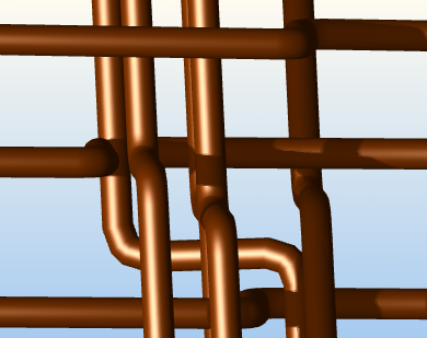
|
|
Three different types of models that can be created using polycylinders.
In addition to their flexibility as a geometric form, polycylinders have only a slightly larger memory footprint than cylinders and can still be rendered more quickly than shells. The following code snippet shows how to create a torus using Insert_PolyCylinder:
    /* creating a list of points for the torus */
    HPoint torus[65];
    static float radius[] = {0.25f};

    for (int i = 0; i < 64; i++) {
        /* Calculating points for the torus*/
        float angle = 2.0f * 3.1415926536f * i / 64.0f;

        float x = 1;
        float y = (float)cos(angle);
        float z = (float)sin(angle) - 1.5f;

        torus[i].Set(x, y, z);
    }

    /* setting the last point to the first point to enclose the torus */
    torus[64] = torus[0];

    HC_Insert_PolyCylinder(65, torus, 1, radius, "none");
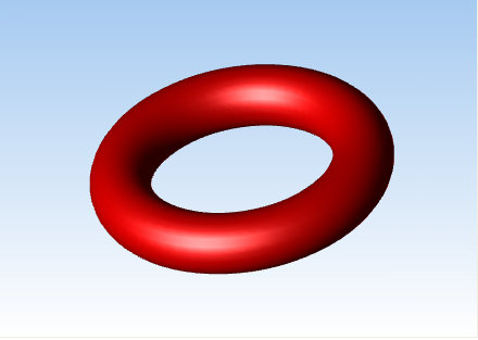
A torus created using the HC_Insert_PolyCylinder function.
You can set the face normals on the two end caps of a polycylinder. The end cap face indices are 0 and 1. The following code sample shows you how to set the face normal on a polycylinder’s end caps:
        static float radius[] = {0.25f};
        HPoint tube[2];
        tube[0].Set(0, 0, 0);
        tube[1].Set(0, 0, 1);

        HC_KEY key = HC_KInsert_PolyCylinder(2, tube, 1, radius, "both");

        HC_Open_Geometry(key);
        {
            HC_Open_Face(0);
            HC_Set_Normal(0, 0, -1);
            HC_Close_Face();

            HC_Open_Face(1);
            HC_Set_Normal(0, 0, 1);
            HC_Close_Face();
        }
        HC_Close_Geometry();
Precision Control
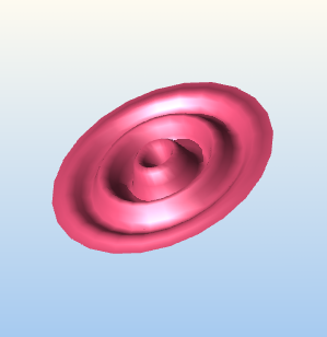
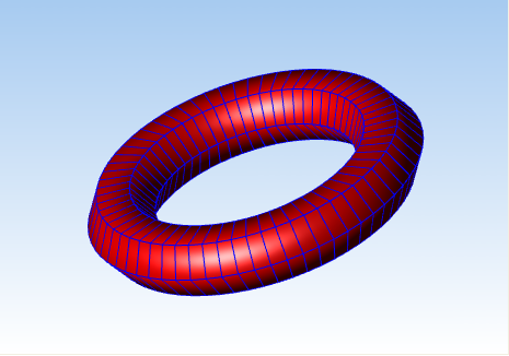
Cylinders and polycylinders, like shells, contain LOD representations. The rendering option “tessellation” specifies the number of facets used to represent the cylinder for each LOD level. When you specify zero for the tessellation value, cylinders will rendered as a single edge between the two end points. This edge will have visibility and attributes of edges (not lines or faces as seen in Set_Visibility). When a negative number is set for the facet value, nothing will be drawn at all. Default resolutions are “tessellation = (cylinder = (24,12,6,0,-1))”.
A torus created with the tessellation set to five.
Color and Color Interpolation
Like shells, you can set the color value for the edges and faces of a polycylinder. In addition, you can also set the color of the individual vertices. When the rendering option “color interpolation” is enabled and color values are set on individual vertices, HOOPS will perform color interpolation between the vertices of the polycylinder. This feature of polycylinders is particularly useful because polylines do not have color interpolation. So to simulate color interpolation for polylines, create a polycylinder with a radius equal to 0 and then, set the color values on your individual vertices. The following sample code shows how this can be achieved:
        int const vertex_count = 5;
        HPoint posFrame[vertex_count];
        posFrame[0].Set(1, 1, 0);
        posFrame[1].Set(-1, 1, 0);
        posFrame[2].Set(-1, -1, 0);
        posFrame[3].Set(1, -1, 0);
        posFrame[4].Set(1, 1, 0);

        char const* colors[] = {"blue", "green", "red"};

        int color_count = sizeof(colors) / sizeof(colors[0]);

        HC_Set_Rendering_Options("color interpolation=on");
        float radius = 0;
        HC_KEY key = HC_Insert_PolyCylinder(vertex_count, posFrame, 1, &radius, "both");

        HC_Open_Geometry(key);
        {
            for (int i = 0; i < vertex_count; i++) {
                HC_Open_Vertex(i);
                {
                    HC_Set_Color(colors[i % color_count]);
                }
                HC_Close_Vertex();
            }
        }
        HC_Close_Geometry();
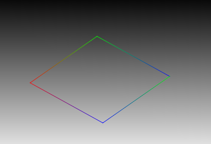
Color interpolation being performed on a polycylinder with radius equal to zero.
Note that if you want to set the color on an end cap, you can set it indirectly by setting the color of the vertex associated with that end cap. Color values can be set via Set_Color_By_Index, MSet_Vertex_Colors_By_Value and its variants.
Another feature of note is the ‘invert polycylinders’ suboption found in “geometry options” via Set_Rendering_Options. When this option is enabled, you flip the order upon which the color and/or radii are applied to points in a polycylinder quickly and easily.
Limitations
Although cylinders and polycylinders are an extremely versatile and highly efficient geometry primitive, there are limitations that affect how they can be used. The following is a list of the restrictions associated with cylinders:
- Changes in the tessellation resolution are the only form of LOD allowed on cylinders. Unlike with shells, it is not possible to use
Open_LODto insert arbitrary geometry or modify the contents of a LOD If such functionality is required, shells, not cylinders, are the appropriate primitive. As described above, however, the special case of 0 resolution has a non-cylinder representation. - Cylinders are never broken lengthwise into pieces, making it impossible to have a specular highlight in the middle of a cylinder using Gouraud shading (though it would be possible with Phong).
- Unlike with shells, the individual faces and edges of cylinders may not be assigned local visibility, or local attributes beyond what is described in the previous section.
- There is currently no mechanism to assign a starting point for the faceting so that the cylinder will exactly match up with other geometry, though cylinders should match up with each other.

