
Cutting Planes
A cutting plane allows you to cut away part of a scene. For example, if you have a scene representing a house, you can cut away everything above the ceiling line (to remove the roof), so that you can see the layout of the rooms. A cutting plane is considered geometry, and it affects (cuts) all geometry in the same scene (under the same driver-instance segment). A scene can contain more than one cutting plane - geometry is removed if it is cut away by any cutting plane.
The following command inserts a cutting plane:
HC_Insert_Cutting_Plane(a, b, c, d);
…where the arguments are (floating-point) coefficients for the plane equation for the cutting plane. The plane equation is:
ax + by + cx + d = 0
The plane itself is all points (x, y, z) in space that satisfy this equation. The part of the scene that is cut away is all points (x, y, z) that satisfy the following inequality:
ax + by + cz + d > 0
You can visualize how the plane equation defines a plane as follows: for some arbitrary cutting plane in space, imagine the line that passes through the origin and is perpendicular to the cutting plane. The (a, b, c) part of the plane equation is a point on this line, and d is the distance from the plane to the origin, in units of the vector from (a, b, c) to the origin. This formulation works even if the plane contains the origin. Note that, for any plane, there is an infinite number of values for (a, b, c, d) that define it (since we can multiply both sides of the plane equation by any positive constant).
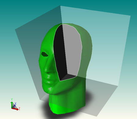
Continuing our house example, let us say that we want to cut away everything whose y coordinate is greater than 0.8, so the cutting plane is perpendicular to the y axis. The vector (0, 1, 0) is in the direction of the y axis, and is conveniently chosen to be of length 1.0. The distance from the cutting plane to the origin in units of this vector is -0.8.
Cutting plane.
The equation of the cutting plane above is 0*x* + 1*y* + 0*z* + -0.8 = 0, which gives us:
HC_Insert_Cutting_Plane(0.0, 1.0, 0.0, -0.8);
Everything above this plane - in the direction of the vector (0, 1, 0) - will be cut away. To cut away everything below this plane, we negate each of the arguments, as follows:
HC_Insert_Cutting_Plane(0.0, -1.0, 0.0, 0.8);
Cutting-Plane Attributes
Like all geometry, the cutting plane is affected by the net transformation matrix of the segment where it is located. The transformation matrix allows you to rotate and translate a cutting plane in space.
Other than that, the main attribute that affects cutting planes is visibility. The command:
HC_Set_Visibility("cutting planes = off");
…will effectively turn off a cutting plane, and will keep a cutting plane in another part of the database tree from affecting local geometry. For example, consider the segment tree:
A graphics database containing a cutting plane.
Normally, the cutting plane in segment B will cut all geometry in the same window, including the geometry in segment C. If you turn off cutting-plane visibility in segment B, then the cutting plane is effectively turned off (it has no effect on any geometry in the scene). If you turn off cutting-plane visibility in segment C, then the geometry in segment C is not affected by the cutting plane in segment B (but geometry in other segments will still be affected).
We can use the ability to turn off cutting-plane visibility selectively, to do partial cutaways. For example, imagine a scene containing a sphere and a cube, with the cube entirely inside the sphere. We want to cut away one-half of the sphere, so that we can see the cube inside, but we do not want to cut the cube. We put the cube and sphere into separate segments, and turn off cutting-plane visibility for the cube.
Local Cutting Planes
What if we want a cutting plane to only affect the segment (and underlying segment tree) where it resides, rather than affect the entire scene underneath a windowed segment? Being able to selectively turn off cutting places as described above doesn’t help us, because we still want cutting planes to take affect. If we want cutting planes to behave in such a ‘local’ manner, we can use the “local cutting planes” rendering option:
HC_Set_Rendering_Options("local cutting planes = on");
Cut Edges/Faces
Cut edges and cut faces (sometimes referred to as cutting or capping geometry) denote the edges/faces of intersection between a cutting plane and the faces in a shell/mesh, and are discussed in the shells attributes section.
Cutting Sections
Normal cutting planes result in the union of the “cut away” parts, which can be viewed as the intersection of the “kept” parts. The planes within a section behave in the opposite manner with respect to each other, so that 2 intersecting planes in a section remove a wedge instead of leaving a wedge. The current cutting_plane becomes a section defined with 1 plane. Multiple sections and/or planes act together in the same manner as cutting planes, where each new cutter removes some additional portion of the scene. Cutting sections are created by calling Insert_Cutting_Section:
HC_Insert_Cutting_Section(count, planes);
Here is an example of a 3-sided cutting section:
Extracting Cutting Plane Geometry
HOOPS Visualize offers you the ability to extract the capping geometry created by a cutting plane. The capping faces are delivered in the form of shells to the currently open segment. Edges are delivered as polylines.
The algorithm must have a definite path from the segment that contains the cutting plane to the window segment, and you must supply a key path for this purpose.
To extract the capping geometry, and delete the associated model, you could do something like this:
    // insert cutting plane to cut the model
    HC_Open_Segment_By_Key(myModelKey);
    HC_KEY cutKey = HC_Insert_Cutting_Plane(1, 0, 0, 0);
    HC_Close_Segment();

    // extract the geometry to a segment called "/caps"
    HC_KEY capsKey = HC_Open_Segment("/caps");
    count = HC_Gather_Capping_Geometry(1, myKeyPath, cutKey, "segment only");
    HC_Close_Segment();

    HC_Open_Segment_By_Key(myViewKey);
    // delete everything in the segment
    HC_Flush_Contents(mySegmentPath, "everything");

    // include the segment where the capping geometry is stored
    HC_Include_Segment_By_Key(capsKey);
    HC_Close_Segment();
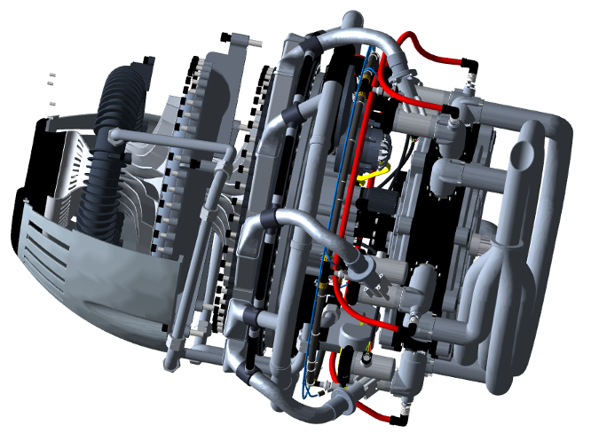
The model before inserting a cutting plane.
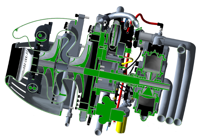
The model after inserting a cutting plane. Notice the capping geometry in green.
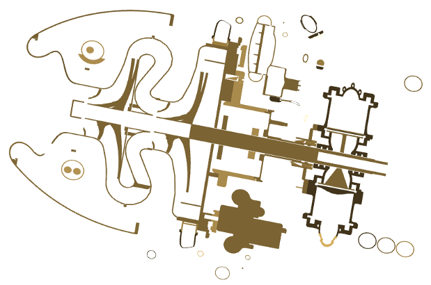
The capping geometry remains after deleting the model.

