Lighting and Color Interpolation
Lighting Interpolation
Also referred to as smooth shading, this rendering option causes facetted objects such as shells, meshes and NURBS surfaces to be displayed as if they were smooth, curved surfaces. Lighting interpolation only applies if there are one or more lights in the scene. If lighting interpolation is off, then ‘flat shading’ will be performed, which causes each facet to have a single uniform color. There are three types of lighting interpolation: Gouraud, Phong and gooch.
Gouraud
The Gouraud shading algorithm computes the light at each vertex, and then interpolates that value across the face. It is enabled by calling the “lighting interpolation” suboption of Set_Rendering_Options:
HC_Set_Rendering_Options("lighting interpolation");
It is also the default method used to draw shell/mesh/surface faces if a light is present in the scene. Gouraud shading is almost always accelerated by underlying 3D hardware. It has some shortcomings, where specular highlights may not be rendered accurately, and ‘phantom’ triangle artifacts can appear, where the underlying triangulation of the model can sometimes be noticed.
Phong
The Phong shading algorithm computes the light on a per-pixel basis, and is enabled by calling the “lighting interpolation” suboption of Set_Rendering_Options:
HC_Set_Rendering_Options("lighting interpolation = Phong");
This results in more accurate display of curved surfaces, and enhances the display of specular highlights.
Phong shading is computationally intensive, and has typically not been used for interactive scenes. However, HOOPS/3dGS can take advantage of graphics hardware to render Phong scenes at speeds that are comparable to Gouraud lighting performance. (It uses some tricks to do so.) This enables developers to enable Phong lighting and obtain visual quality improvements without incurring the performance hit associated with Phong lighting that makes it impractical to use for interactive scenes). However, the developer should first check if Phong lighting is supported by the graphics hardware before setting it. HOOPS/3dGS users can do this by calling ::Show_Device_Info after the first update:
    char result[128];
    HC_Show_Device_Info("/driver/opengl2/window0", "Phong lighting", result);
If the device does not support Phong lighting and Phong lighting is still enabled, HOOPS/3dGS will punt to software, and the only indication that the users will receive that such has happened will be poor performance. The following are some key points about hardware Phong lighting support:
- It should be used only in cases where the light follows the camera or objects are rotated using modelling matrices. If end users are able to position themselves to see specular highlights from grazing angles on the surface, bad artifacts can appear.
- Phong lighting has a fairly small amount of initialization overhead per update, which is based on the number of HOOPS/3dGS subwindows and the number of unique gloss values. If scenes contain multiple gloss values and/or subwindows, the overhead can add up.
- Use of local, area, or spot lights will cause HOOPS/3dGS to fall back to software rendering. Only distant lights (
Insert_Distant_Light) are compatible with hardware Phong support. - We have found performance (with a large model and a single distant light) to be approximately 10% worse than standard Gouraud shading, but the improved quality is more than worth it.
- Transparent materials will produce a more severe slowdown.
- The specular color of materials will be ignored. Only the light’s specular color will be honored. For the purposes of hardware Phong shading, the material’s specular color is assumed to be pure white.
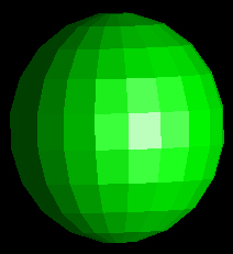
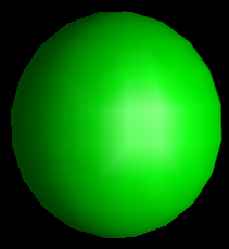
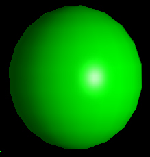
Flat, Gouraud, and Phong-lit spheres:
|
|
|
Flat, Gouraud, and Phong-lit spheres
Eye-Dome Lighting
Eye-dome lighting is a shading technique used to improve depth perception. This lighting method is non-photorealistic and is commonly used when visualizing point clouds. Normally, when you want to apply a lighting effect to a point cloud, you would have to set a normal for each vertex in the cloud. This is not only tedious, but requires significant memory resources. Eye-dome lighting is designed to solve this problem. To enable eye-dome lighting, simply enable it as a driver option:
HC_Set_Driver_Options("eye dome lighting = (on, strength=1.0)");
Note that eye-dome lighting is a window-level attribute that is intended to be used only with point clouds. However, if your scene includes both point cloud data and facetted data, you would typically want to disable the effect for the facetted data. As a frame buffer effect, eye-dome lighting can be disabled for a segment sub-tree using:
HC_Set_Rendering_Options("frame buffer effects = off");
Keep in mind that the above call will disable all frame buffer effects for that segment sub-tree. This is one of the trade-offs of using eye-dome lighting with both point clouds and facetted data.
If you are seeing banding artifacts or other graphical anomalies when using eye-dome lighting, reducing the strength parameter may help to improve the image quality. However, this will also result in detail reduction.
Eye-dome lighting is demonstrated below. The top image has eye-dome lighting enabled, while the bottom image is unlit:

Gooch
Gooch rendering is a non-photorealistic shading model that has become popular in recent years because it draws from some of the techniques used in technical illustration. The following sample code shows how to set the lighting interpolation to gooch:
HC_Set_Rendering_Options("lighting interpolation = gooch");
In addition to taking colors from physics-based lighting equations, gooch rendering also blends them with a color scheme that uses artist’s techniques. Highly lit surfaces are assigned a “warm” color, whereas areas with facing away from the light are given a “cool” color. The total effect is that lighting becomes a color shift in addition to the usual light to dark transition. To set the colors for gooch rendering, you indicate the color range by passing two indices in a predefined color-map by setting the suboption “color range” in “gooch options”. Color ranges can include multiple intermediate colors.
    HC_Set_Color_Map("red, blue");

    HC_Set_Rendering_Options("gooch options=(color range=(0.05,0.95))");
The colors used for gooch are not limited to the color map in the current segment. To use a color map in another location, simply set the “gooch options” “color map segment” with the location of your preferred color map.
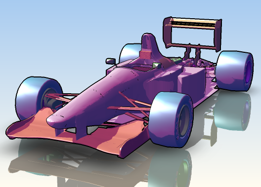
|
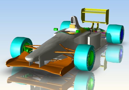
|
The race car model on the left is rendered with gooch using a color map consisting on navy and fuchsia while the model on the right is rendered with Gouraud.
Users can control the relative contribution of the non-photorealistic component versus the usual diffuse lighting using the “gooch option” called diffuse weight. A diffuse weight of one yields an image that is identical to Phong shading while a diffuse weight of zero means that the physical lighting equations make no contribution at all.
HC_Set_Rendering_Options("gooch options=(diffuse weight=0.50)");
Color Interpolation
Many 3D applications offer the ability to visualize non-graphical data associated with a model. The most common scenarios include showing the barometric pressure in a meteorological map, streamlines over an aircraft and altitude lines on a topographical model. In all these scenarios, color is used as a visual indicator of information that otherwise might not be perceived in the application. HOOPS aids in these scientific, geological or other applications through the color interpolation feature.
By default, color interpolation, which is a rendering option, is turned on. However, you cannot see the effects of color interpolation without setting the color on the vertices of a face. When different colors are set on each of the vertices of a face, HOOPS performs a color interpolation across the associated face and/or edges. The following code sample shows how to set colors on vertices to get a color interpolation effect.
    HC_KEY key = HC_Insert_Shell(pcount, pts, flist_count, faces);
    HC_Open_Geometry(key);

    HC_Open_Vertex(0);
    HC_Set_Color("red");
    HC_Close_Vertex();

    HC_Open_Vertex(1);
    HC_Set_Color("orange");
    HC_Close_Vertex();

    HC_Close_Geometry();
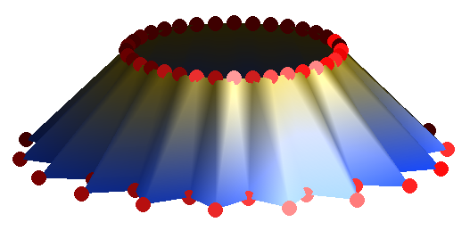
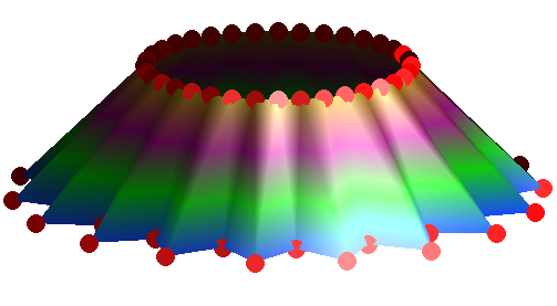
Shows a shell rendered with color interpolation.
Color Index Interpolation
In most cases when color interpolation is employed, individual colors have a specific value or range of values associated with them. For instance, if you want show a topographical map with different colors representing different altitude, you might create a color map. In the rendering of the topographical map, you want to show banded colors that are represented in the color map. To do this, instead of using the “color interpolation” rendering option, use the “color index interpolation” option which interpolates between the indices of a color map rendered as banded colors.
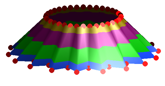
Shows a shell rendered with color index interpolation.
If you want to interpolate between the indices of a color map but also want a blended instead of banded effect, you can turn on both “color interpolation” and “color index interpolation” rendering options.
Shows a shell rendered with color interpolation and color index interpolation.
Learn more details about this feature on the setting color by fractional index section page. If you want to experiment further with color index interpolation and color interpolation, please take a look at the sample program interpol.c <examples/interpol.c>. See the HOOPS/3dGS Reference Manual for more information on Set_Color_By_FIndex command.
Contour Lines
Color interpolation and color index interpolation can be employed successfully to represent nongraphical data in a visual way. Additionally, using contour or isolines can give more detail, elaborate and integrate several different dimensions of data. For instance, a topographic map using color index interpolation gives the viewer a sense of varying altitudes at different locations.
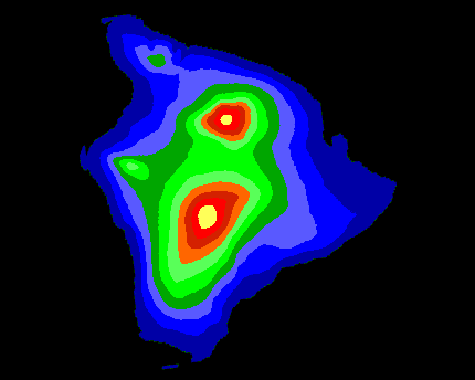
A topographic map of the big island of Hawaii.
Now, if we wanted to used the same topographic map but additionally show barometric pressure at different elevations, we could add contour lines to display this information. To do this in HOOPS, we use the “isoline options”. These options have a variety of suboptions, the first of which is visibility. Once isolines are visible, we can set the position, color, pattern and weight.
HC_Set_Rendering_Options("isoline options = (visibility=on)");
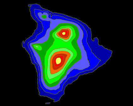
A topographic map of the big island of Hawaii with contour lines that show barometric pressure.
The “isoline option” for position can be set either by specifying an interval and an offset or at explicit positions. In the code snippet below, we can see how both of these options can be set:
    // Setting the positions of isolines with an interval
    HC_Set_Rendering_Options("isoline options = (positions =(repeat= (interval= 0.5, offset=1.3)))");

    // Setting the positions of isolines explicitly
    HC_Set_Rendering_Options("isoline options = (positions =(explicit=(1,2,3,4))");
The color of isolines is by default set to the interpolated color value. If we want a contrasting or specific color, we can set it in “isoline options”. HOOPS accepts the color specification as described in Set_Color. If we want to override only some isolines color, we can use the ‘-’ symbol to specify that you want a given isoline to inherit interpolate color value. If we want isolines to inherit the edge color, use the ‘*’ symbol. In the code snippet below, the call to Set_Rendering_Options is setting the first isoline color to the edge color, then the second one to the interpolated value and finally the last one to blue. These three values will be repeated throughout.
HC_Set_Rendering_Options("isoline options = (color = (*, - , blue)");
Note that although we can set the color and position of isolines via “isoline options”, what HOOPS renders to the screen is not only of function of this option but also the “color index interpolation options”. Within this option is the ability to determine a color map is applied to the surface of your geometry. The value adjustment suboption lets you normalize the color map values so that they range from 0 to 1. Or you can scale and translate the color map values. Thus, if this option is set, color and position values set in “isoline options” will be applied on top of any “value adjustment” that was set.
The two “isoline options” that are not directly affected by “color index interpolation options” are pattern and weight. By default, the pattern and weight of isolines are inherited from the edge pattern and weight respectively. You can override these values in “isoline options” for each isoline. Pattern options are the same as those specified in Set_Edge_Pattern while weight values are as specified in Set_Edge_Weight.
Contour Lines Without Color Index Interpolation
So far, we have discussed adding contour lines to a model rendered with color index interpolation enabled. Although this combination of features is a powerful tool for data visualization, there are situations where isolines can be used on their own.
Going back to the map of the big island of Hawaii. If we want to spotlight information about barometric pressure, we could continue show isolines but instead of using color index interpolation to show elevation, we can apply a texture map to the model.
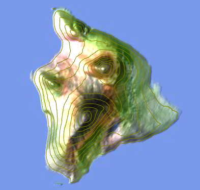
A topographic map of the big island of Hawaii.
The code sample below shows we can set rending options so that we can achieve this effect:
    HC_Set_Rendering_Options("no color index interpolation, color index interpolation options = (value adjustment = none), "
                             "isoline options = (visibility = on)");