Controlling the HOOPS/Parasolid Mapping
As mentioned in the previous section, the HP_Render_Entity function instructs HOOPS to insert the tessellated geometric primitives into the currently open HOOPS segment. The methods by which the HOOPS/Parasolid Integration maps the tessellated representation of Parasolid entities to HOOPS segments and geometric primitives are controlled using the function HP_Set_Rendering_Options. NOTE: this function is different than the HOOPS/3DGS function called HC_Set_Rendering_Options, which controls how the HOOPS 3D Graphics Systems performs 2D/3D rendering.
Default Rendering Options
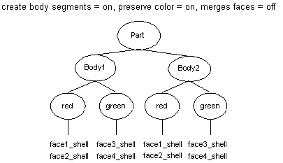
The default mapping behavior will create additional HOOPS subsegments within the currently open segment for each Parasolid body being rendered. Because each HOOPS segment has one opinion about each HOOPS attribute (color, line_pattern, modeling matrix, etc…), such a segment hierarchy facilitates applying unique sets of attributes to the group of geometric primitives that represent a Parasolid body. (The new attribute can be directly set on the unique HOOPS segment associated with the body.)
The default mapping also preserves any color attributes which may have been stored in the Parasolid kernel by creating a HOOPS segment for each unique color in the Parasolid kernel. These segments are created underneath each body segment. Creating multiple segments for each color is again necessary due to the attribute coherence rule of a HOOPS segment. Though some HOOPS geometric primitives (shells and meshes) can be individually colored, the other primitives are rendered using the color and other attributes set in the containing segment.
The integration also maps each Parasolid PK_FACE entity, which are rendered as a result of the PK_TOPOL_render_facet call, to a HOOPS ‘shell’ primitive by default. (The alternative is to map multiple PK_FACE entities to a single HOOPS shell, which is supported by the “merge faces” option discussed later in this section.) Mapping each PK_FACE to a single HOOPS shell facilitates Parasolid operations that work at the level of a PK_FACE; it is easier to access an entire HOOPS shell, rather than access a subset of edges/faces/vertices within a HOOPS shell. Each PK_EDGE entity is mapped to one or more HOOPS ‘line’ primitives, which include ‘line’, ‘polyline’, ‘arc’, ‘circular arc’, ‘ellipse’, and ‘elliptical arc’.
The following diagram depicts how two Parasolid bodies, each containing two different colors, would be mapped to the HOOPS database using the default Mapping_Options; the ‘part’ segment denotes the currently open segment at the time the PK_TOPOL_render_XXX calls are made:

Effects of the Rendering Options Preserve Color
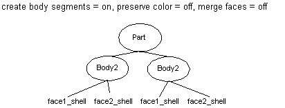
Setting the rendering option “preserve color = off” instructs HOOPS to ignore any color attributes stored in the Parasolid kernel when mapping Parasolid entities to the HOOPS database. HOOPS will not create subsegments within the currently open segment for each unique color:

Color attributes are frequently stored in Parasolid files, hence color should typically be preserved when reading in a file. ( HP_Read_Xmt_File() ) Additionally, when dynamically creating/inserting a Parasolid entity, it is useful to set the entity’s desired color inside of Parasolid so that the color will be stored along with the entity when writing out an Xmt file. In this common situation, color should also be preserved so that the corresponding HOOPS segments/geometry will be rendered with the correct color. However, if there is no need to either create entities with different/specific colors, or to preserve color information contained in a file, “preserve color = off” may be used.
Body Segments
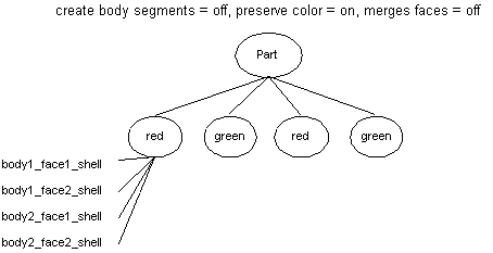
Setting the mapping option “create body segments = off” instructs HOOPS to not create extra subsegments within the currently open segment for each body.

Because each HOOPS segment has one opinion about each HOOPS attribute (color, line_pattern, modeling matrix, etc…), such a segment hierarchy does not allow for attribute granularity among the various geometric primitives that represent the Parasolid geometry rendered within the currently open HOOPS segment. It only allows attributes to be set based on the color partitioning of the segments. Any HOOPS attribute that is set on the ‘red’ segment in the above example will affect all geometry in the segment; hence all bodies that are being represented will be affected equally by the attribute change. If a body needed to have a unique modeling matrix applied to it, its associated HOOPS geometry would have to be identified via the HP_Compute_TagID and HP_Compute_Geometry_Keys() functions, and moved into a separate segment that contained the new modeling matrix. In contrast, if the default segment structure outlined in the beginning of this section was used, the new attribute could be directly set on the unique HOOPS segment associated with the body.
Merge Faces
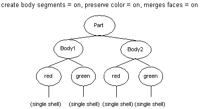
Setting the mapping options “merge faces = on” instructs the Integration to merge all the HOOPS shells that were generated to represent a PK_BODY (one shell for each PK_FACE) into a single HOOPS shell. In the case of a multi-colored PK_BODY, the shells corresponding to PK_FACES that have the same color attribute will be merged into one HOOPS shell, resulting in as many HOOPS shells are there are distinct colors in the PK_BODY entity.

This mapping results in optimal rendering speed at the expense of ease of manipulating individual PK_Body entities. Applications that are concerned only with viewing, or that do not need to select at the PK_FACE level (to perform ‘face-level’ Parasolid operations) will gain significant rendering speed advantages by making use of this feature.

