Modeling Matrices
Each HOOPS segment contains a 4x4 matrix which affects the segment’s geometry. A modeling matrix is an attribute, with a default value being the identity matrix.
Modifying Modeling Matrices
A segment’s local modeling matrix can be modified by either:
- supplying the matrix directly (using
Append_Modelling_MatrixorSet_Modelling_Matrix) - using standard routines such as
Rotate_Object,Scale_Object, orTranslate_Object
Matrices behave a bit differently than other attributes in that a segment’s modeling matrix is concatenated (and hence multiplied) with its parent segment’s matrix. This lends itself to manipulating a 3D hierarchy, which might involve animation, etc… One key point to be aware of, however, is that multiplication of matrices is not commutative. Since the level of a segment in the tree defines the order in which a matrix will be applied in the list of matrices, it is important to set the desired transform at the correct location. Since modeling matrices behave like other segment attributes, all objects in a segment will be affected by the local modeling transform. Therefore, if you need to transform specific objects within a segment you need to copy objects into a separate segment and then apply a transform.
Modeling Matrix Example
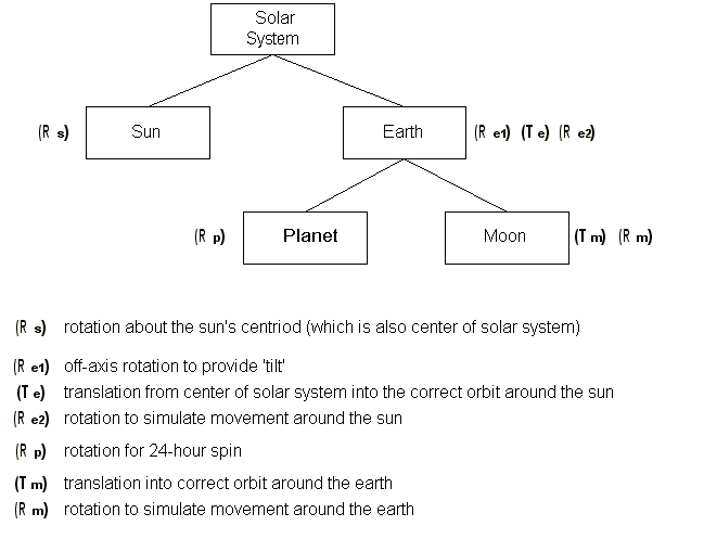
Let’s take the example of the solar system again, and design a segment tree which enables us to accurately simulate how planets and their moons move about the system over time. Each object that has local behaviors (such as a rotation, etc..) needs to have its own local object space, and therefore needs a segment associated with it. If we want to model the sun, the earth and the earth’s moon for starters, we would need this sort of segment tree:

Segment tree with necessary transforms for sun, earth and moon
Note that the earth is composed of a parent segment and two subsegments, one which will hold the actual planet geometry, and the other the moon geometry, since they have their own local movements. (The earth rotates relative to its centroid. The moon rotates about the earth and does not have its own local rotation.) However, since they are both subsegements of the ‘earth’ segment, any transforms applied to the ‘earth’ parent segment will affect the planet/moon combo equally. Let’s assume that each object is represented by a HOOPS shell in the shape of a sphere, and each shell is modeled around the origin. Keep in mind that initially (before there are any transforms), all the objects would be drawn on top of one another since each segment’s local object space has the origin as its centroid.
At each time slice in the simulation, we need to animate the various components of the system. Let’s itemize what must happen with each object at each time slice:
Solar System: Technically, the entire solar system is rotating about the centroid of our galaxy, and would therefore require a rotation transform. However, since we’re only interested in modeling the solar system, we can ignore this fact. Therefore, we won’t apply any transforms to the entire solar system.
Sun: The sun remains at the origin, but requires a rotation transform.
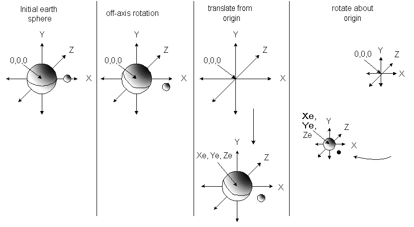
Earth: This segment represents the ‘earth system’ and requires several transforms per update. It first needs a local rotation transform to account for the off-axis tilt of the earth (which also affects the moon). This is a constant value (it is the same during each time slice). Then, since the earth-system is modeled around its own local object space with the origin at 0,0,0 (same as the origin of the sun’s local object space), it needs to be translated away from the origin. Finally, the earth-system of course rotates around the sun over a period of 365 days, so we then apply another rotation transform. So, during each time slice of the simulation, the earth-system is rotated, translated, and rotated. The following image depicts the sequence of the ‘earth-system’ transforms during each update (note that the sun remains at the origin, and Xe, Ye, Ze denotes the new location of the earth’s centroid after transforms have been applied):

Transforms applied to the ‘earth-system’
Note that the order of these transforms is important.
Planet: The earth geometry requires a transform to reflect its continual 24-hour rotation about its axis (note the its axis will also be modified via the first rotation applied in the ‘earth’ segment, discussed above.)
Moon: The moon geometry requires a transform from the origin so that it is drawn at the appropriate distance away from the earth, and then requires a rotation which will model its movement around the earth which is approximately once per month.
Masking Modelling Transforms
It may be useful in certain cases to have HOOPS/3dGS ignore rotations, scales, or translations that are the result of a modification to the modelling matrix. An example would be the creation of handles for moving objects in the scene. As the local object is scaled, you wouldn’t want its handles to scale. (but only to rotate and translate). The “mask transform” in rendering options allows you to do this:
HC_Set_Rendering_Options("mask transform = (camera=[rotation/scale/translation])");

