3DGS Technical Overview
What is the HOOPS 3D Graphics System?
The HOOPS 3D Graphics System (HOOPS/3DGS) is a high performance 3D graphics toolkit for developers building applications for the Windows and UNIX operating systems and the Internet. HOOPS/3DGS’ highly optimized data structures and algorithms dramatically simplify the development of 2D and 3D, interactive, vector and raster graphics-based CAD/CAM/CAE, scientific visualization, and Geographical Information System (GIS) applications.
HOOPS/3DGS contains:
- A subroutine library that provides for the creation, management, querying and editing of an application’s graphical information and is linked with an application’s object code. The libraries can be dynamically or statically linked.
- A large suite of supporting demonstration and integration code to assist developers in learning about HOOPS/3DGS and incorporating it into their application.
- Application developers combine their core application logic with HOOPS/3DGS and the user interface to develop interactive graphics applications.
The HOOPS/3DGS Architecture
HOOPS/3DGS is a retained mode graphics system with a database architecture. HOOPS/3DGS provides the algorithms for creating, editing, manipulating, and querying the graphics information stored in the database. This encapsulates the graphical data in HOOPS, coupling it with an interface layer. This coupling of data structures with algorithms is the fundamental principle of object-oriented design.
Data-encapsulation, messaging, instancing and attribute inheritance are also fundamental design elements of HOOPS/3DGS. While HOOPS/3DGS is not implemented as a class library, its architecture employs these fundamental aspects of object-oriented design.
The HOOPS/3DGS libraries are incorporated directly into the application’s build process, i.e., linked with the application’s other object code to produce the executable image. The developer uses the HOOPS/3DGS API to create and manage geometrical objects from within the other components of their application.
The HOOPS/3DGS Graphics System, illustrated below, consists of two major subcomponents: a graphical object database called the HOOPS/3DGS segment tree, and a rendering pipeline called the HOOPS/3DGS structured device interface.
HOOPS/3DGS Segment Tree and Rendering Pipeline
Retained-Mode Graphics System
Graphics systems that render primitives immediately, without storing them in a display list, are called immediate mode systems. Systems that store graphics information in data structures specifically designed for the display of graphics are called retained mode graphics libraries. HOOPS/3DGS is a retained-mode graphics library. Retaining the graphics primitives in a retained mode system provides significant benefits:
Performance: If the graphics system (rather than the application) retains a copy of all the primitives, it can perform faster modification and traversal of the graphics information as well as optimizations to make rendering the scene faster. For example, the graphics system can calculate bounding volumes that store the location and a rough measure of the extent of a set of primitives. During rendering, many primitives may not be visible on the screen. Bounding volumes allow the system to quickly determine whether a group of primitives is on-screen so that only those graphics primitives that are actually visible are sent to the display hardware to be rendered.
Selection: An important function of a graphics system is performing selections (also called “picking”), where the graphics system determines which graphic primitive the user is pointing at with the cursor. Without a display list, the only way for the graphics system to perform a selection is to have the application resend all the primitives since they were not retained by the graphics system. A display list allows the graphics system to perform selection much faster, typically an order of magnitude faster.
Window system support: If a window containing a scene is partially obscured by another window and then it is brought to the front, the newly-exposed areas of the window need to be redrawn. If the graphics system stores the primitives in a display list, then the window can be redrawn without going back to the application. (The window’s image can also be stored as a bitmap, allowing instant redraws of damaged areas. HOOPS/3DGS supports this method as well.)
Global rendering algorithms: Many kinds of renderers require a copy of all the graphics primitives. For example, for ray tracing and radiosity, the color of an object is affected by other objects, so the renderer requires data on all the primitives before it can start drawing any of them. Such advanced rendering algorithms require the use of a display list to store the primitives.
The Object Database
The HOOPS/3DGS database stores graphical data in objects called “segments”. Think of a segment as a container for geometry and attributes that describe how the geometry is to be drawn. Segment-to-segment relationships are hierarchical and are described as “parent-child” pairings or, as one segment “owning” others (its children). The mapping is one to many; that is, one parent segment may have many child segments but every child segment has one unique parent segment.
Segments may be instanced several times and inserted into the tree in multiple places. This process is called inclusion, as in “one segment includes another”. Often, only the attribute set of a segment needs to be instanced and used by other segments; this process is called styling. Inclusion and styling are discussed in more detail below the section on style segments.
These segment to segment relationships result in a hierarchical tree structure, or more specifically, a directed acyclic graph. This structure enables attribute inheritance. Child segments have the same attribute values as their parent segment, unless they specifically have their own local settings for certain attributes.
The HOOPS/3DGS database structure ensures optimal speed by partitioning the geometric data into objects with homogeneous attributes. This minimizes the need to change hardware display context during drawing of the graphical information and optimizes display-list throughput.
Coordinates and Coordinate Systems
In HOOPS/3DGS, as in most graphics systems, points in space are specified using Cartesian coordinates. HOOPS/3DGS routines always take three x, y, and z coordinates; this means all points in HOOPS/3DGS are three-dimensional. However, a z-value of zero indicates a two-dimensional object, so HOOPS/3DGS uses more optimized two-dimensional rendering routines as appropriate.
Coordinates in HOOPS/3DGS are specified using single-precision floating point numbers. By default, however, C and C++ perform floating point arithmetic using double-precision (64 bit) numbers. These double-precision numbers are converted to single-precision when passed to a HOOPS/3DGS call.
HOOPS/3DGS includes a double-precision module that enables double-precision floating point values to be used when creating and querying geometry. It does this by providing variants of all the HOOPS/3DGS routines for geometry creation, editing, and querying, as well as for several of the coordinate system conversion routines.
Inserting Geometry By Reference
When geometry is inserted into the HOOPS/3DGS database, HOOPS/3DGS makes a copy of the supplied data; this is normal for a retained-mode system and necessary for data encapsulation. For some kinds of geometry, this data can be quite large. Making a copy wastes space and makes the application bigger and slower than it needs to be.
To avoid this problem, HOOPS/3DGS allows for the insertion of meshes, shells, and images by reference. Inserting geometry by reference tells HOOPS/3DGS that it is acceptable not to make a copy of the data. For a mesh, this data is the point list. For a shell, it is the point list and the face list. For an image, it is the image data.
Interfaces
HOOPS/3DGS can be called from C, C++, C#, and Java.
Database Traversal
The information in the database must be examined and formatted for the specific device interface available on the computer hardware. This operation is referred to as database traversal. The internal traversal routine “walks” from segment to segment in the tree and sends the information it finds to the rendering pipeline.
A single subroutine call, Update_Display, instructs HOOPS/3DGS to walk the database tree, visiting each node that contains something to be drawn. To draw a segment, HOOPS/3DGS sends any geometry it contains to the rendering pipeline along with the segment’s attributes, and recursively draws any sub-segments. Consequently, drawing a segment draws the entire branch of the tree with that segment as the root.
Because HOOPS/3DGS is a declarative graphics system, the order in which HOOPS/3DGS traverses the tree (or even whether it traverses the entire tree) is not important. This allows HOOPS/3DGS to choose how it walks the database. There are several types of decisions HOOPS/3DGS can make to control/minimize the amount of geometry sent to the rendering pipeline, thereby enhancing performance or improving usability. They include:
- Selective traversal: Because HOOPS/3DGS keeps track of portions of the display that are not changing between updates, unnecessary redraws are eliminated and damaged portions of the screen can be either selectively redrawn or instantly re-blitted from the software z-buffer or software frame buffer.
- Incremental updates: HOOPS/3DGS contains update logic that allows geometry to be incrementally added to a scene without a full redraw.
- ** Time-Bounded updates** - HOOPS/3DGS can be instructed to redraw as much of the scene possible within a specified amount of time.
- Single-driver updates - An update can be performed on a single driver instance. For example, in some cases the developer may want to update a postscript driver tree, but to avoid a display update. The update can also be performed on a separate thread, enabling the hardcopy to be generated while the user returns to interacting with the display.
Rendering Pipeline: The HOOPS/3DGS Structured Device Interface (HDI)
Key to the optimized performance of HOOPS/3DGS is its rendering pipeline, called the HOOPS/3DGS Structured Device Interface (HDI). HDI accepts information found in the segments, reformats it for the hardware output device interface, and sends it to the device for drawing. HDI successively decomposes the information, passing the database information through software mapping layers until it is in the format the output device can handle.
If the hardware device interface understands 3D information (as with OpenGL), HOOPS/3DGS can pass along information without much change. But if the device interface only understands 2D pixels (as with Xlib or GDI), several layers of decomposition must be used. This ensures both optimal rendering throughput on a given device and consistent functionality of the HOOPS/3DGS API across multiple platforms and devices. This process is presented in the figure below:
HOOPS/3DGS Structured Device Interface (HDI) Architecture
HDI ensures that application performance scales to system capability. Even on a system with graphics hardware, in some cases HOOPS/3DGS software can be faster than the hardware due to highly optimized rendering algorithms.
Flow of Control
The flow of control in a typical HOOPS-based application proceeds as follows:
- The end-user of the application generates events via the user interface in effort to create new or manipulate existing application data (graphical or non-graphical).
- The application code makes some changes to the information stored in HOOPS/3DGS.
- HOOPS/3DGS then traverses the segment tree, determines what should be drawn, and sends this information to the HOOPS/3DGS Structured Device Interface which reformats it for the output device’s capabilities and then sends it along to the output device.
- The output device receives the information from the graphics system and draws the graphical information on the monitor or printer.
- The user sees the new picture, decides what they want to do next and generates new input events with the user interface. (This takes us back to step 1.)
HOOPS as an Object-Oriented System
Object-oriented Design (OOD) is just that: design. Once complete, designs must be realized or expressed in a medium. In computer science terminology, the medium is a computer language, like C, C++, FORTRAN, Cobol, Java, etc. While the syntax of some languages encourages the developer to design in an OOD fashion, languages with less rigorous syntactical structure do not hinder the expression of object-oriented designs. Object-oriented architecture is independent of language and can be implemented in any language.
The main themes of object-oriented design are:
- Encapsulation of object interfaces (methods)
- Data Hiding
- Attribute Inheritance
- Reuse of objects via instancing
HOOPS/3DGS was designed prior to the presence of stable, mature implementations of C++. While HOOPS/3DGS is not implemented as a class library, its design incorporates each of these OOD elements. The ability for the HOOPS’ development team to continually add functionality to the library over time and for HOOPS/3DGS to flexibly adapt to emerging APIs is strong testimony to its object-oriented design.
Encapsulation and Data Hiding With Segments
The HOOPS/3DGS graphics database stores graphics scenes as a hierarchy of segments, which lends itself naturally to organizing graphics information. In terms of object-oriented programming, think of a segment as an object.
- A segment encapsulates a public interface. Most HOOPS/3DGS commands modify the state of a segment, or return information about a segment or its contents.
- A segment uses data hiding to protect the internal details of its representation from the programmer. This makes life simpler for the programmer by hiding unnecessary details. It allows HOOPS/3DGS to modify its internal representation on different platforms for portability, to take advantage of faster algorithms, or to incorporate improved rendering techniques.
- A segment has attributes, which act similarly to the member variables of an object.
- A segment can have one or more sub-segments. The hierarchy formed by the segments in the database is like the class hierarchy in an object-oriented language (but more dynamic).
- Just as member variables are inherited by a class’ subclasses, attributes are inherited by a segment’s sub-segments. This form of inheritance is called attribute inheritance.
- A segment can be reused through the use of include segments and style segments.
- A segment contains a single list of the geometry that belongs to the segment.
A segment contains geometry, attributes, and sub-segments.
Segment Pathnames and Handles
The entire segment tree is rooted under one segment, the root-segment, denoted with a forward-slash “/”, and each segment occupies a unique spot in the segment tree, called its pathname. There are several different ways to identify and subsequently reference a segment:
- Implicitly - Calls to HOOPS/3DGS attribute and geometry commands reference the currently open (active) segment, or more specifically, the most recently opened segment.
- Explicitly, by name - You can refer to a segment by its full pathname by using an ASCII string with the ‘/’ denoting sub-segments. For example “/driver/msw/window0” would refer to the “window0” segment which is a sub-segment of “msw”, etc.
- By Key - Accessing a segment by key is often more convenient and significantly faster than by name because keys don’t require a name lookup. A key is a long integer and is returned by HOOPS/3DGS when a segment is initially created. Keys are commonly used to associate HOOPS/3DGS segments and geometry with application data (such as a data structure pointer).
Instancing and Reuse With Include Segments
HOOPS/3DGS has two kinds of sub-segments: regular segments and include segments. Include segments support a form of reuse. Include segments are similar to symbolic (soft) links in the UNIX file system because they allow multiple links to the same object. An included segment (also called an instance of a segment) behaves like a regular sub-segment, except that the parent of an included segment is always its real parent, not the segment that includes it.
A segment to be included actually lives as a normal segment (with its own geometry, attributes, and even sub-segments) in another part of the graphics database. For convenience, HOOPS/3DGS provides a place called “?Include Library”.
Driver Segments
HOOPS/3DGS automatically defines a segment named “/driver”. Underneath this segment are a dozen or more pre-created sub-segments- one segment for each kind of device for which HOOPS/3DGS has a device driver. These sub-segments of “/driver” are called driver segments. These are abstract classes and are not to be used directly, but rather instanced and built upon.
Each sub-segment of a particular driver segment is an instance of that driver, or more specifically, a unique connection to an output device. For a display driver on a window system like X11 or Windows, each instance corresponds to a connection to a window on the display. For a hardcopy driver like PostScript, each instance corresponds to a file to be printed. For example, “/driver/msw/window0” refers to a window on the MSW (Microsoft Windows) display device.
This image provides a graphical representation of segment hierarchy in HOOPS/3DGS:
Default segment hierarchy
Messaging and Methods
Interface layers for communicating with graphics information in a database typically are either declarative or procedural. With declarative interfaces, the programmer declares what *is to be displayed. With procedural interfaces, the programmer declares details of *how to display the information. HOOPS/3DGS provides a declarative interface.
Procedural graphics systems have been found to be more difficult to use than declarative graphics systems. Because a segment can contain more than one value for an attribute in a procedural graphics system, it is much harder to find the value of any particular attribute, and harder still to change the value of an attribute and know to what geometry the attribute will apply. In addition, such systems cannot support attribute inheritance (in the object-oriented sense) like HOOPS/3DGS does.
In object-oriented programming, data is encapsulated in the object and hidden from external users of the object. An interface layer of methods is presented for creating and manipulating the internal state of the objects’ data. HOOPS/3DGS declarative interface provides just such a mechanism for external manipulation of the internal information.
Attribute Inheritance
Attribute inheritance in HOOPS/3DGS works just like inheritance in an object-oriented language. If an attribute value is not set locally on a segment, it is inherited from a parent segment. Attribute values that are set explicitly on a segment are called local attributes. These are attributes set with any HOOPS/3DGS Set command, such as Set_Color or Set_Line_Weight.
When HOOPS/3DGS renders the database, it needs to know the attribute values for all the geometry in the database. To determine the values of attributes, HOOPS/3DGS first looks at local attributes set on the current segment. If any required attributes have not been set on the local segment, HOOPS/3DGS looks in the parent of this segment to see if a local attribute was set on it, and then its parent, and so on, until it finds a value for the attribute.
Default Attribute Values
When you start HOOPS/3DGS, it sets a local value for every attribute on the root segment of the database tree. When looking for the value of an attribute, HOOPS/3DGS eventually finds its way up to the root of the tree, and then uses the value found there. So the local attribute value set on the root segment of the database acts as a default value for the attribute value. The default value assigned by HOOPS/3DGS can be changed by changing the local attribute value on the root segment of the tree.
Another way to look at this is that any time a local attribute is set on a segment, a default value is established for all segments below that one in the tree. Thus, in a scene with multiple complex graphical objects, each one represented by its own subtree, you can have different default values for each object by setting local attributes on the root segments of their subtrees.
Nonstandard Attribute Inheritance
Most attributes inherit their values from their parent segment. However, a few attributes inherit their values in a nonstandard manner.
Consider a modeling transform: a translation, rotation, or scale. Modeling transformations are always performed with respect to the parent segment. When an object is rotated, for example, it is useful for all of its children to rotate as well (even if they have their own local modeling transformations).
A segment’s local modeling transformation is concatenated (using matrix multiplication) onto the modeling transformation of its parent- it doesn’t simply replace it. If a segment has no local modeling transformations, the net transformation for the segment is the same as its parent’s net modeling transformation. But if a segment does have a local modeling transformation, it is concatenated onto the net modeling transformation of the parent segment.
There are also a few attributes that inherit up the tree; for example, bounding volumes. The bounding volume of a parent segment is the union of the bounding volumes of its children segments, plus the bounding volume of the parent segment’s geometry.
A few attributes, such as normal vectors, do not inherit at all. The HOOPS/3DGS reference manual entry for each type of attribute includes a discussion of any non-standard inheritance characteristics for that attribute.
Attribute Lock
It is possible to override local attributes temporarily, using attribute lock. When a specific attribute is locked in a segment, that attribute’s value applies to all sub-segments, regardless of whether those sub-segments have local attribute values set for that same attribute. For example, attribute lock can be used to highlight a part of the database by changing the color of everything to red, temporarily ignoring any local color attributes.
Style Segments
HOOPS/3DGS provides a convenient way to take a set of attributes and make them apply to a large number of segments. You can create a segment called a style segment. Then, you can make other segments reference the style segment, thereby causing the other segments to take on the attributes of the style segment. Attributes that are “styled” act like local attributes.
Attribute Inheritance Summary
Rendering the database consists of walking the database (segment tree), constructing primitives, and rendering these primitives. From the viewpoint of the renderer, a segment consists of geometry and net attributes. “Net attribute” refers to the fact that an attribute’s value is determined based on (in order of priority, from 1 to 3) its local value, its style segment value, or its inherited value.
A segment from the viewpoint of the renderer
The geometry along with the values of the net attributes are drawn by the renderer. From the viewpoint of the database tree walker, the net attributes of a segment come from three places: locally set attributes, style segments, and parent segments. (Note: This discussion applies only to attributes that inherit normally.)
A segment from the viewpoint of the database tree walker
In this diagram, local attribute values are attributes that are explicitly set on a segment using one of the HOOPS/3DGS Set routines. Style segment attribute values come from the local attributes of a segment that is used to “style” the current segment using the ::Show_Style_Segment routine. Inherited net attribute values (typically) come from the net attributes of the parent segment of this segment.
Geometry and Attributes
In HOOPS/3DGS, geometry is the raw geometric information (such as points or lines) that defines the visual components of the picture. Segments are containers for geometry and attributes. Attributes are used to specify how the geometry stored in the database should be rendered and queried.
Geometry Provided in HOOPS/3DGS
The HOOPS/3DGS interface contains entry points for each geometric primitive in the form: Insert_XXX, where XXX is the name of the primitive (for example, Insert_Line, Insert_Mesh, or Insert_Distant_Light.) The geometric entities supported by HOOPS/3DGS have been specifically tailored for the needs of the MCAD/CAM/CAE software industry.
All geometric entities in HOOPS/3DGS are represented as flat, infinitely thin surfaces- i.e., there are no solid objects in HOOPS. In order to create an object that appears to be solid, you define the collection of its infinitely thin surfaces. Markers, text, and images differ slightly in that markers and text are defined by one 3D point and have no real surfaces, while images have a 3D anchor point and a 2D pixel array defined in screen space, which is mapped to the pixels of an output device.
HOOPS/3DGS provides the following geometry:
- Circles
- Circular arcs
- Circular wedge
- Circular chord
- Ellipses
- Elliptical arc
- Grids
- Images
- Infinite lines
- Infinite rays
- Lines
- Markers
- Meshes
- Polygons
- Polylines
- Shells
- Text
- Cylinders
- Polycylinders
- NURBS curves
- NURBS surfaces
Once geometry has been inserted into HOOPS/3DGS segments, it can be copied, deleted, modified, or manipulated. The position of geometry in the world coordinate system is governed by the information given on insertion and the net modeling matrix in effect on the geometry’s containing segment.
Markers
A marker is a single location in space. The location is drawn with a symbol such as an X, a dot, or a circle. Markers are commonly used to mark data points in a graph, or locations on a map. HOOPS/3DGS directly supports over 30 marker symbols commonly used in the MCAD and AEC industries, and has mechanisms for adding user-defined symbols via HOOPS/3DGS Intermediate Mode.
Text
Text is inserted as a string with a 3D coordinate as a reference point. Text can be rendered in screen space or as fully transformable strokes. Font, size, slant, rotation and alignment can be individually controlled. HOOPS/3DGS provides direct support for Unicode (UTF-8, UTF-16 and UTF-32), Japanese Kanji and ISO-Latin character sets.
HOOPS/3DGS includes an embedded font engine and routines that enable standard fonts to be converted to 3D surfaces. The font engine enables HOOPS/3DGS-based applications to incorporate Adobe Type I (PostScript), TrueType and BitStream’s Speedo fonts in a scene by simply setting the text font name attribute. This conversion also enables HOOPS/3DGS rendering techniques such as texture mapping and lighting to be applied to the geometry generated from the fonts. HOOPS also ships with its own font, TS3D, which can render GD&T symbols.

A model rendered with PMI information using GD&T symbols.
HOOPS/3DGS provides support for native Windows (GDI) and Unix (X11) system bitmapped fonts. This allows the system fonts to be integrated into the OpenGL scene, and enables developers to write portable font search/usage logic that will provide consistent results across the OpenGL, MSW-Display, MSW-Printer, and MSW-Clipboard drivers.
Multiline (block) text is supported and the line spacing is controllable. Text greeking is also supported, which involves drawing a simple box at the text location if the text is going to be rendered below a certain size.
Underline, overline and strikethrough text is supported. Text rendering is highly optimized. The bitmaps for system fonts are cached and used during drawing, and the triangles/outlines for 3D fonts are also cached and drawn when rendering text in full 3D.
Lines and Polylines
A line is a segment with two endpoints. HOOPS support lines and its variants including polylines, infinite lines and infinite rays.
Polygons
A polygon is a flat, infinitely thin surface in space and is defined by the vertices along its perimeter. A polygon consists of two separate parts: the edge and the face. Attributes such as face pattern, edge weight, edge pattern, visibility and color can be set on these parts independently.
Circles and Ellipses
A circle is defined by any three points on its circumference. Circles are grouped with ellipses, polygons, shells, and meshes for rendering purposes. Their rendition may be adjusted with the attributes for faces and edges.
Circular Arcs
A circular arc is defined by three points on the circumference of a circle. The order of the points is important. The arc begins at the first point, draws through the second, and continues to the third. Circular arcs are grouped with lines, polylines, and elliptical arcs for rendering purposes.
Circular Chords
A circular chord is defined by three points on the circumference of a circle. The order of the points is important. The chord begins at the first point, draws through the second point, and continues through the third point. A line connects the first and third points.
Circular Wedges
A circular wedge is defined by three points on the circumference of a circle. The order of the points is important.The wedge begins at the first point, draws through the second point, and continues through the third point. The center of a circle defined by the three points is computed and lines are drawn from the first point to the center and from the third point to the center.
Ellipses
An ellipse is defined by three points: its center point, and intersection points with its major and minor axes. It is grouped with the set of polygonal entities for rendering purposes.
Elliptical Arc
An elliptical arc is defined by the same information for an ellipse, plus two floating point numbers between 0 and 1 which indicate the normalized parametric angle along the perimeter of the ellipse where the arc begins and ends.
Shells
A shell is an arbitrary collection of polygons that forms a three-dimensional object. A shell can represent: 1) points (like a scatter plot), 2) edges (a series of lines), or 3) polygons. A shell that represents a polygon would be an array of points and a connectivity list that describes the polygonal faces. A useful way to visualize these two components is as a point cloud and a collection of “connect-the-dots” sequences in the point cloud.
A shell consists of one or more polygonal faces and is typically used to represent a wide range of geometric objects such as cubes, spheres and parametric surfaces. The advantage of using a shell, rather than multiple independent polygons, is that the shell takes up less memory in the database, is faster to render, and can be smoothly shaded.
Shells can be inserted by tristrips (trifans can also be specified), and the tristrips that HOOPS/3DGS has calculated can be queried.
Shell and mesh faces have the same attributes as polygons. They also have several features that go beyond the capabilities of polygons:
| Vertex markers | 
|
The vertices of a shell/mesh are represented as markers which are subject to normal marker attributes. You can change the marker symbol and size for these markers, and you can turn the markers off with Set_Visibility('markers=off'). For most uses of shells, it is common to turn the visibility of markers off. However, if you want to visualize shell data as a ‘point cloud’ or as ‘point splats’, you might render this data as a shell with no faces and enable marker visibility as well as turn on hardware acceleration for marker rendering as described in the vertex markers section of the Programming Guide. |
| Attributes on sub-parts | 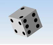
|
Unlike other kinds geometry, attributes can be set on individual faces, edges, and vertices within a shell or mesh. The flexibility of this feature allows freedom to create varied objects by manipulating attributes like color, texture maps and visibility. For instance, you can set different color values on each vertex or face of your shell. You can also apply different textures on different faces of your shell to create a six-sided die. |
| Smooth shading | 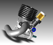
|
Because vertices can be shared between shell and mesh faces, these primitives can be smooth shaded using Gouraud and Phong lighting interpolation algorithms. Lighting interpolation requires HOOPS/3DGS to have a normal vector for each vertex in the shell or mesh. HOOPS/3DGS can automatically compute normal vectors for each vertex, or they can be defined by the user. |
| Data mapping | 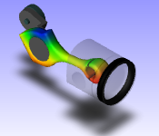
|
In addition to performing lighting interpolation (smooth shading), colors can be interpolated across a shell or mesh. This is used to visualize data associated with the surface. For example, color may be used to indicate temperature distribution across a surface. The method for achieving this consists of associating either floating point or integer scalar values with the vertices of a mesh or shell then using these values to determine color values for the surface at the vertices by using them as indices into a color map. Color values can be interpolated so that the color changes smoothly across a face, or color indices can be interpolated with the result being contour bands. Isolines can also be displayed. |
| Rendering techniques | 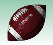
|
HOOPS Visualize supports a wide variety of effects that can produce a more valuable experience for the end user. These effects include texture, bump and environment mapping. You can also set the multiple layers of transparency on your shells. To give the end user a better idea of shape, Visualize offers support for simple shadows, shadow mapping, ambient occlusion and hemispheric ambient lighting. In addition to these effects, you can also add a reflection plane and control the visibility of attributes in the model and the reflection independently. |
| Cutting lines/capping faces | 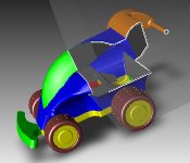
|
If a cutting plane is present, the lines or faces of intersection between the cutting plane and the shell faces can be displayed; their visibility, color, pattern, and thickness can be individually controlled. |
Regions
Sometimes it is important to be able to logically define a shell into specific functional areas. You can do this with region. A region is defined as a collection of facets within a shell. This allows users to more easily manipulate the attributes of discrete areas of a shell, and facilitates data mapping between the application and the geometric objects.
Meshes
A mesh is a two-dimensional array of 3D points with fixed topology. A mesh is like a rectangular wire screen- it can be bent into an arbitrary curved surface but the points in the mesh are connected into quadrilaterals. Meshes and shells are the only primitives in HOOPS/3DGS with the connectivity information for adjoining faces enabling the Phong and gouraud lighting interpolation methods to be used.
Grids
A grid is a flat array of faces, edges, and markers. It can be quadrilateral or radial, finite or infinite.
Images
An image is intended for the display of raster arrays of pixels. An image is unique in that it is laid out in terms of screen space; once the center has been located in 3D space, all other parameters (format, height and width) are defined in terms of pixels on the screen of the current display device. Images can be used as part of sophisticated materials mapping techniques like environment maps and skyboxes.
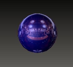
A sphere rendered with environment and mirror values to reflect a bar scene.
HOOPS/3DGS supports the following image formats:
- RGB - 24 bit true color
- Mapped 16 - 16 bit indices into a HOOPS/3DGS color map
- Mapped 8 - 8 bit indices into a HOOPS/3DGS color map
Lights
HOOPS/3DGS supports distant, spot, and point sources of light. Multiple lights can be inserted, and each light can have a unique color. HOOPS/3DGS performs lighting calculations for all the objects in the scene that contain a light. The positions of each type of light can be manipulated with modeling transformations; spot lights can be configured to follow a camera as it is manipulated.
Cutting Planes
A cutting plane “cuts away” part of the scene. In particular, if you consider the [a,b,c] portion of a plane equation as the normal vector for the plane, then that half-space by convention is left open, i.e., it is not cut away. Multiple cuttings planes can be inserted in the segment tree.
NURBS Curves and Surfaces
A Non Uniform Rational B-Spline (NURBS) is defined by a series of control points, weights, knot vectors, and a degree. This is the standard primitive used to represent analytic or free-form shapes. Attributes set on lines/faces apply to NURBS curves/surfaces as well. HOOPS supports a variety of NURBS-related rendering options to provide control over the facetting budget/tolerance. Trimming is also supported.
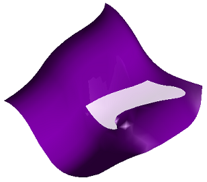
A NURBS surface with a curve trim.
Cylinders and Polycylinders
A cylinder is defined by 2 points, a radius, and a boolean indicating whether it should be capped. The tesselation of cylinders can be controlled. On the other hand, polycylinders are defined by a series of 3D points and a corresponding array of radii of equal length. This primitive is useful for applications that model piping systems. Geometry that can be represented by this entity include torii, straight and non-straight pipes, tanks, arrows and tubes.
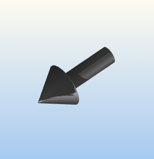
An arrow rendered by using polycylinders.
Attributes
Attributes in HOOPS Visualize are used to specify how the geometry stored in the database should be rendered and queried. There are some non-graphical attributes as well, most of which help the system attach to and configure output and input devices. The main types of attributes in HOOPS Visualize are:
- Display
- Modeling and viewing
- Rendering
- Selection
- Driver options
- System options
- Heuristics
Display Attributes
Display attributes specify how different types of geometry should be drawn - what color to use for polygons, what edge pattern to use on lines, face patterns for meshes, symbols for markers, and so on. They are segment level attributes. Each geometric type in the same segment can, and often does, have its own setting in the same segment. For example, the lines in a same segment may have a different color attribute from the text.
Color and Color Maps
The color of geometry in HOOPS/3DGS may be specified with one of four color space models: RGB, HLS, HIC, and HSV. With regards to the HIC color space model, HOOPS/3DGS also defines the color names of the Crayola64 color set, so textual names such as ‘orange’ and ‘bright blue’ may be used.
A color map attribute may be defined and color values given as indices into the color map. Color maps may be defined in any of the 4 color space formats, or as Crayola names. The user may elect to define his own set of color names defined in any of the available color space models.
HOOPS/3DGS supports monochrome, mapped (i.e. 8-bit) and true color (i.e. 24-bit) devices by using a 24-bit color model internally and automatically dithering colors for mapped devices via a dither cube. The size and shape of the dither cube HOOPS/3DGS uses are configurable.
Double-side coloring/lighting is supported, which allows color to be set differently on the front and back faces of shells/meshs or polygons.
Visibility
Often, it is useful to control whether geometry and/or segments are drawn without affecting the overall structure of the segment hierarchy. The visibility attribute provides this level of control. Segments and geometry whose visibility attribute is set to “off” are not drawn during an update cycle. You can control many elements independently, such as interior silhouettes (edges), perimeters, mesh quads, and ‘hard’ edges which display the ‘boundary’ or ‘feature’ aspects of a model.
Edge Pattern and Weight
There are separate attributes for controlling the width and pattern of the edges of polygons, circles, ellipses, shells, and meshes.
Face Pattern
Face pattern enables patterns to be applied to the faces of polygons, circles, ellipses, meshes and shells.
Capping Faces/Edges and Geometry Intersections
HOOPS can calculate and display the edges/facets of intersection between a cutting plane and shell/mesh geometry. It can also calculate and display the polylines of intersection between shell objects.
Modeling and Viewing
The modeling and viewing attributes in HOOPS/3DGS define what geometry is being viewed in the segment tree and how it is mapped to a windowing system window. HOOPS/3DGS employs the paradigm of cameras and windows for the viewing and modeling transformations.
Cameras exist in the same world space as the geometry and can ‘see’ the geometry in the segment tree. The contents of their field of view is then mapped into a HOOPS/3DGS window. HOOPS/3DGS windows are subregions of a root window corresponding to an instance of a driver segment which is attached to an output device. Thus, all windows below the driver segment are subregions of the output device window or printer page, and their contents are mapped to the output device.
Modeling
Modeling attributes provide for the scaling, rotating and translating of the geometry contained in a segment and, due to attribute inheritance, its sub-segments. If the order in which successive modeling transformations are applied to geometry is changed, the resulting net transformations will be different. (Modeling transformations are non-commutative operands.) Thus, these attributes are the only ones in HOOPS/3DGS that are order-dependent.
Each segment in HOOPS/3DGS has a local 3D space and geometry inserted into a segment is said to be in that segment’s object space coordinate system. Any transformation attributes set on the segment will modify the position of the geometry in the segment. Since modeling transformations are attributes, the final position of the geometry depends on the modeling transforms set locally in its containing segment and of all the modeling attributes set in the line of segments owning it.
HOOPS/3DGS provides for either right or left-handed coordinate systems to be used on a per-segment basis. The same segment hierarchy may have multiple instances with different handedness settings.
Viewing with Cameras
HOOPS/3DGS uses the paradigm of cameras to define views into a scene. Cameras have a position, target, up vector, field of view and a projection. Supported camera projections include perspective, orthographic, and oblique. These values are defined with 3D coordinates in world space. HOOPS/3DGS cameras may be manipulated in the same way as their real-world counterparts with routines that dolly, roll, zoom, pan, rotate and orbit.
As cameras are segment-level attributes, it is quite possible to have multiple cameras defined under the same driver level segment. The geometry visible in each camera’s view will then be projected into the containing (net) window. This may be an attribute of the same segment as the camera or a parent segment. This is a useful technique for generating stereo effects for added depth perception.
The needs of most applications are met by relying on the default camera associated with a driver instance segment and its associated HOOPS/3DGS window.
Developers can construct arbitrary convex clip paths (using the HOOPS IM interface), which allow ‘detail’ or irregular viewports.
Windows
Window attributes are segment-level attributes and therefore inherit. The visual effect is that of nested sub-regions. Window attributes of child segments are defined as sub-regions of the first window found above them in the hierarchy. The top level window is the one at the driver instance segment and it maps to the extents of the output device.
Rendering Attributes
Rendering attributes are used to select algorithms for calculating hidden surfaces, lighting effects, the mapping of associated data to geometry (e.g., stress-strain analysis results mapped to a mechanical parts geometry) as well as the level of detail (LOD) to be used when displaying shells and meshes. HOOPS/3DGS’ rendering functionality also includes transparency, texture mapping, OpenGL display-lists, anti-aliasing, stereo-viewing, atmospheric attenuation (depth-cueing), color contouring, isolines, environment mapping, face-displacement, and dynamic LOD switching.
Lighting Models
HOOPS/3DGS provides flat (faceted), gouraud (smooth), Phong lighting techniques (including hardware-accelerated Phong); and both diffuse and specular reflections. Gouraud and Phong shading are only applicable to shells and meshes.
3D-Spriting
Spriting enables transformation and editing of geometry in a large scene (and in true 3d) without redrawing the entire scene. Only an initial full redraw is necessary at the very beginning of the spriting process, and this redraw can be scoped (and thereby sped up) by using Control_Update. This powerful feature allows a developer to greatly enhance the way that the end-user interacts with geometry, particularly if there is a lot of geometry in the scene.
Data Mapping
Often, it is desirable to map data associated with a surface directly on to that surface, particularly in the CAE areas of Finite Element Analysis (FEA) and Computational Fluid Dynamics (CFD). HOOPS/3DGS provides the capability of mapping scalar information (integer or floating values) directly onto surface topology and then using this information to calculate color contours across the surface. Hard contours (also called fringe-plots) are hardware-accelerated.
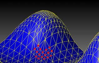
Level Of Detail (LOD)
The rendering performance of large models can be improved by generating multiple versions of the model’s geometry, each with smaller amounts of data or levels of detail (LOD), and then dynamically choosing which version to render based on different criteria. For example, multiple LODs for a shell or mesh can be generated each with a smaller number of triangles using a vertex decimation technique and then those LODs can be chosen for rendering as the user manipulates the camera viewing the model; LODs with more detail are rendered when closer to the model and LODs with less detail used when further away.
The HOOPS/3DGS LOD module provides for the calculation of LODs for shells and meshes as well as enabling the user to supply their own LODs; HOOPS/3DGS primitives can be used as LOD objects. It also provides for dynamic selection of these LODs based on several different types of threshold calculations. Two LOD-generation algorithms are available, one providing better visual results and the other trading visual quality for speed.
Texture and Environment Mapping
HOOPS provides support for tiled, clamped, mirrored, and environment-mapped textures. Texture definition support includes color channel mapping, interpolation filtering, brightness control, and six different parameterization descriptions.
Overlay Geometry
Users can specify the Z-buffer range for objects in a segment. This allows specific pieces of the scene to be drawn on top at all times. (2D overlay geometry, such as geometry that represents a rubberband box for selection, is supported via a HOOPS heuristic called ‘quick moves’. Heuristics are mentioned later in this document.)
Selection
The selection attribute enables control over how the objects in the HOOPS/3DGS database respond to a selection query or hit-test. The application will often need to request that HOOPS/3DGS find the drawing primitive or segment currently being pointed at by an input device, usually a mouse or pen.
Selection settings may be given for the entire contents of a segment or set specifically for certain geometric types within the same segment. For example, to implement “snap-to-grid” behavior, one could insert a grid into a segment and then set the selection attribute for everything except markers to be ‘off’.
Driver Options
These attributes are used to provide information to the HOOPS/3DGS graphics system of special device-specific display options such as
- Double-buffering
- Input event queue control
- Number of colors on the device
- Configure the dither cube for lighting calculations
- Landscape or portrait orientation
- Pen speed (printers and plotters)
- Physical size
- Hardware color map to use, if desired
- Window handle to use, if desired
System Options
System options are used to configure aspects of the entire HOOPS Visualize system. For example, you can control how Visualize conserves memory, set the length of a string, or configure the error reporting. Other examples include:
- bounding volume calculations - user can disable bounding volume calculations
- memory conservation - instructs HOOPS to save memory at the cost of rendering performance
- multi-threading - various levels of multi-threading support can be set, which enable HOOPS to be partially or fully re-entrant (thread-safe). This enables users to create multi-threaded applications, which could, for example, have HOOPS generate a hardcopy from a new thread, and allow the user to return to interacting with the scene on the main thread while the hardcopy is still being generated (specifically, 2 different threads could be traversing, querying, or even modifying the HOOPS database)
Heuristics
Heuristics are hints to give to HOOPS/3DGS to help it make traversal time decisions about how to optimally render the segment tree. By telling HOOPS/3DGS whether or not to use the following information or techniques, the performance of the system may be tuned to a given applications graphics data.
- Backplane culling - HOOPS will perform backplane culling in hardware if available; it also attempts to use CPU-specific extensions to speed up the culling process
- Clipping
- Concave polygons
- Hidden surfaces
- Incremental updates
- Intersecting polygons
- Memory purge
- Polygon handedness - this allows the developer to specify a handedness to allow backplane culling to be performed
- Quick moves - overlayed 3D geometry is supported using XOR or hardware overlay planes; a ‘spriting’ technique (which utilizes underlying OpenGL buffer-region extensions) is also supported which enables 3D objects to be quickly moved about the scene
Input and Hit-Testing
The HOOPS/3DGS architecture includes a mechanism for monitoring input devices for user-generated events. This can be used to build a user interface with HOOPS/3DGS and can be quite useful in the area of rapid-prototyping. More often than not, in commercial applications, this feature is disabled and the application directly controls the event loop, processing all the messages and dispatching them to the appropriate component sub-systems. In this case, events associated with geometry selection (hit-testing) need to be passed to HOOPS/3DGS.
When the application needs to know what geometry the end-user is selecting, HOOPS/3DGS performs a “hit-test” of the input events coordinates against the geometry in the HOOPS/3DGS database. HOOPS/3DGS provides a routine called Compute_Selection which, given a window location, performs a 3D object space intersection test and returns any selected objects. The image below shows the path of a selection event as it starts out as a location event from the window system. The application receives the location event and calls Compute_Selection with the location, which does a hit test against the 3D objects in the database and creates a selection event.
Flow of selection event from window system to HOOPS
HOOPS Visualize supports the following selection methods:
- Aperture - A point location. Aperture is defined by a radial distance from the selection point.
- Area - A rectangular region
- Polygon (lasso) - A polygonal region
- Polyline (fence) - A series of points connected by line segments
- Volume - A 3D object space volume
- Object - A HOOPS/3DGS shell primitive (enables clash-detection/interference-checking between objects)
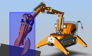
|
Rectangular region for selection |
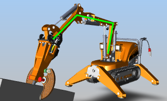
|
Polyline defining a selection area |
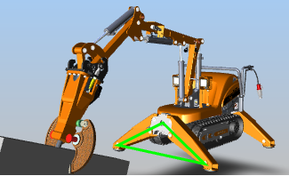
|
Polygon defining a selection area |
Selection methods performed on a tractor model.
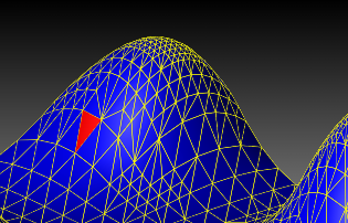
HOOPS/3DGS also supports a range of picking granularity within selected objects:
- Vertex - closest definition point
- Edge -closest polygonal border
- Face - closest polygonal facet
- Object - segment containing the selected geometry
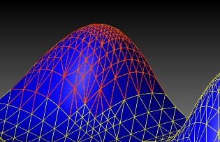
|
Edge selection |
|
Vertex selection |
|
Face selection |
Subentity selection performed on a NURBS surface.
HOOPS/3DGS will also compute the analytical point of intersection with the selected geometry in object, world and camera spaces.
Integrating HOOPS/3DGS with a GUI Toolkit
Just as HOOPS/3DGS is a component for graphics, there are several components that provide graphical user interface (GUI) technology. Typically, developers want to use HOOPS/3DGS with such GUI components as MFC on Windows, MOTIF on UNIX, or Qt and Java for cross-platform GUI.
Window System Integration
When writing a 3D HOOPS-based graphics application, the developer has a choice of writing the user interface in HOOPS/3DGS or in the target platform’s native window system. In most cases, it is desirable to write the user interface using a window system. This allows the application to have a native ‘look and feel’ and allows the graphics system to remain independent of the event queue and user interface. HOOPS/3DGS has been successfully and seamlessly integrated with MFC, MOTIF, QT, Java, and ActiveX GUI tools. This work is encapsulated into the HOOPS/GUI modules and included as part of the HOOPS 3D Application Framework.
Drawing Into Native Application Windows
Normally, HOOPS/3DGS creates its own output window for each driver instance. When the user interface is written using a window system, the window system is in charge of creating the output window. To address this need, HOOPS/3DGS is able to accept a pre-created window to draw into. The application simply passes the window handle to an instance of a HOOPS/3DGS driver level segment.
Color Map Sharing
HOOPS/3DGS provides mechanisms that allow you to share colormaps among multiple driver instances and applications.
HOOPS/3DGS Intermediate Mode
HOOPS/3DGS Intermediate Mode is a secondary interface layer in the library and provides access to the immediate mode routines used in the HOOPS/3DGS Structured Device Interface layer. HOOPS/3DGS Intermediate Mode complements the classic HOOPS/3DGS library and provides for traversal-time modifications of the object hierarchy (segment tree). The diagram below illustrates the relationship between HOOPS/3DGS’ database API, the HC interface, and the immediate mode API, the HIC Interface.
The relationship between HOOPS/3DGS’ HC and HIC APIs.
HOOPS/3DGS is a retained graphics database system. You create a scene by inserting geometry and setting attributes in a segment tree maintained by HOOPS/3DGS. When you call Update_Display (or you request input), the system traverses the segment tree and draws the picture on the display device. To learn more about the rendering pipeline for each type of geometry, see the HOOPS/3DGS Programming Guide section on HOOPS Intermediate Mode.
With the classic HOOPS/3DGS library, additions and modifications to the segment tree cannot be made while HOOPS/3DGS is traversing the tree. The Intermediate Mode library provides a means for the application to trap the HOOPS/3DGS update cycle at certain points in the rendering pipeline by means of a callback mechanism.
When the traversal is trapped at a callback point, decisions can be made about what and how something is drawn, or even the traversal process itself can be aborted. In addition to the callback mechanism, the HOOPS/3DGS Intermediate Mode library provides a set of functions that can be called from the callback functions to draw to the display in an “immediate mode” style and to query the graphics database and the device characteristics.
The HOOPS/3DGS selection feature also involves a traversal of the graphics database contained in the segment tree. However, the selection traversal does not draw on the display. Rather, it computes the screen positions of objects in the database to determine which objects have been hit by selection events. HOOPS/3DGS Intermediate Mode provides callback points at which the selection traversal as well as the update traversal can be trapped.
Why Use HOOPS/3DGS Intermediate Mode?
HOOPS/3DGS Intermediate Mode is useful when it is necessary for the application to be able to make traversal-time decisions about the rendering or selection process, or to accomplish special processing that is not provided by the standard tree traversal process.
Some examples of situations in which to use HOOPS/3DGS Intermediate Mode are:
- You may want the graphical representation of your data, i.e. the actual primitives and attribute values used, to depend on the viewing parameters or the screen transformation. In particular, if your model has a hierarchy of scale and the view is zoomed out sufficiently far, then you may want to skip the rendering of entire subtrees that would appear very small on the display.
- You may want to define your own version of a HOOPS primitive. For example, you could implement a spline drawing algorithm through the HOOPS polyline primitive, using the polyline vertices as spline control points. In this case, you would intercept at one of the callback points in the polyline drawing pipeline, and substitute your own spline drawing routine for the HOOPS Visualize polyline drawing routine.
- Custom marker symbols or line styles are required, and need to be stroked out at traversal-time drawing. In addition, the rendering style may need to be dependent on actual screen size. For example, in a cartographic application railway tracks could be stored as polylines in the database, but be drawn, for certain map scales, as parallel lines with cross ties.
- If the graphics database is voluminous, it may be useful for the application to avoid spending the memory needed for HOOPS/3DGS to duplicate in its database some of the same information already contained in the application’s private data structures. Using HOOPS/3DGS Intermediate Mode in an “immediate mode” style allows primitives to be passed to HOOPS/3DGS one at a time in Intermediate Mode callbacks, rather than storing them in HOOPS/3DGS segments. However, since HOOPS/3DGS no longer “knows about” such primitives, it cannot be used to manage and select them.
- In a real-time application, it may be necessary to be able to modify the picture being displayed according to input received during traversal.

