Shadows
Before adding shadows to a scene that uses backplane culling, please see the backplane culling notes in the ``Set_Heuristics`` reference manual page.
Simple Shadows
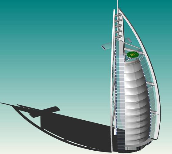
HOOPS Visualize supports simple shadowing of a model using a single, user-defined light source and plane. Simple shadowing is sometimes referred to as fake shadowing, i.e. it does not rely on interpolation. Rather the shadow effect is achieved through use of texture maps. Shadowing is enabled by setting the “simple shadow” rendering option, which also supports modifying the shadow plane, light, opacity and color. For example:
HC_Set_Rendering_Options("simple shadow=(on, plane=(0, 1, 0, 2), color=gray, light=(0.5, 1, -0.2))");
You can modify several shadow options. One of them is the resolution of the shadow texture:
"simple shadow = (resolution = x)"
…where x is a number from 32 to 1024. The current default is 256. Another option is the shadow blurring factor:
"simple shadow = (blurring = y)"
where y is a number between 1 to 31 indicating the level of blurring (softening) that is applied to the shadow. The effect is more noticeable at lower resolutions as the number controls the size of the blur region, which is effectively a smaller part of high-resolution images.
To improve performance of shadow rendering it is possible to specify an arbitrary number of “shadow points” on segments in the model. Segments (and their children) which have a shadow point set generate their own individual shadow which get rendered/updated independent of the rest of the scene. In conjunction with further shadow optimization which allows to skip shadow regeneration in certain cases (e.g. object translation) this allows for a much better performance if parts of the scene are modified. To set a shadow point on a particular segment use the following code:
HC_Set_Rendering_Options("simple shadow = auto");
When HOOPS renders a simple shadow, it honors the transparency values set in the model. In other words, if a surface has a transparency value, the simple shadow cast by this surface will also have the same amount of transparency.

A structure with transparency surfaces casts a simple shadow with transparency values.
If you do not want simple shadows to maintain the transparency value of the model, then you can enable the ‘ignore transparencies’ suboption:
HC_Set_Rendering_Options("simple shadow = (ignore transparencies= on)");
The same structure casting a simple shadow with no transparency values.
Shadow Maps
Under the DirectX11 and OpenGL2 drivers, HOOPS/3dGS supports shadow maps. In shadow mapping, rendering a scene takes two drawing passes. First, the scene is rendered from the light’s (distant and spot lights) point of view. Then, the z-buffer is extracted and stored as a texture. Now it can be used as a shadow map. In the second and final drawing of the scene, each pixel is rendered in the light or shadow based on information from the shadow map. In HOOPS, shadow maps are used to render shadows cast by faces onto any geometry that can be lit. To enable this functionality, turn on the “shadow map rendering option” as well as the “shadow visibility option” at the segment level.
|
|
A scene rendered without shadow maps on the left and with shadow maps on the right.
In the image above, the image to the right was created by setting the follow “shadow map” rendering option to on as well as turning jitter on and setting the resolution and sample to the highest possible values as seen in the following code snippet:
HC_Set_Rendering_Options("shadow map=(on, jitter, resolution=2048, samples=16)");
Using shadow maps can create a more realistic looking scene but there are memory and performance costs. Rendering a scene with shadow maps can result in at least a fifty percent slowdown in rendering performance. However, “shadow map rendering option” provides several parameters you can modify to help you balance the level of visual detail with rendering performance at the scene key level. For instance, you can determine the width and height of your shadow map by setting the resolution parameter. The resolution values can be between 512 and 2048. A higher resolution shadow map can increase the visual quality of your shadows especially around the edges. However, it also means a larger memory footprint. The default resolution is 512.
|
|
A scene rendered with a shadow map resolution of 512 on the left and 2048 on the right. Both scenes have a sample count of 4.
You can also select the number of samples used to determine the amount of light projected on each pixel in the final scene. Valid values for the sample option are 1, 4, 9 or 16. If the sample parameter is equal to one, when HOOPS calculates each pixel value to render the scene, it looks up one corresponding value in the shadow map to determine whether a pixel is in shadow or not. When the sample count is greater than one, it takes the specified number of samples from the shadow map and averages them to create a percentage value representing how much light should be applied to the pixel. If a pixel is clearly in light or shadow, taking more samples will have no effect on the rendered scene but for pixels that lie on shadow edges, more samples can reduce aliasing effects and soften shadows. Note that increasing the number of samples taken for each pixel requires more processing cycles during render time.

|

|
A scene rendered with a sample count of 1 on the left and 9 on the right. Both scenes have a shadow map resolution is 1024.
HOOPS provides another parameter under the shadow map option called jitter. When jitter is enabled, HOOPS performs an additional calculation when taking samples from the shadow map. Instead of taking samples that directly correspond to the pixel’s location in the shadow map, a stochastic function is applied to the process of determining where to take samples. If shadow edges in your scene are particularly jagged and sharp, jitter may improve the scene visually by creating a white noise effect around these areas.
|
|
A scene rendered with jitter off in the left image and jitter on in the right image. Both images have a sample count of 4 and shadow map resolution of 512.
By default, shadow maps are recalculated in a view dependent fashion. In other words, shadow maps are recalculated every time the camera changes position taking into consideration the new view frustum. This improves the quality of the shadows especially if the camera is zoomed in, but incurs some extra per-update calculation time. If the camera will not be zoomed in and you have non-camera relative lights , the ‘view dependent’ suboption of “shadow map rendering option” can be set to ‘off’, to improve performance slightly.
|
|
This pair of images shows a model with shadows rendered without the view dependent option. Notice that the shadow resolution remains the same even in the zoomed image. The second pair of images shows the same model rendered with view dependent option enabled.
|
|
This pair of images shows the same model as in the previous image, but this time the second image is rendered with view dependent shadows. Notice in the zoomed right image, the shadows are sharper than in the left image.
Once you have enabled the “shadow map” rendering option, you will need to enable the “shadow option” in Set_Visibility to see shadows in your scene. This can be done on a per segment basis. The “shadow visibility options” have three parameters: casting, receiving and emitting. Setting the shadow visibility options to “on” is shorthand for turning on casting, receiving and emitting. The casting parameter lets you determine if a piece of geometry will cast a shadow. In HOOPS 3DF, only faces can cast shadows. Note that anything in quick moves or spriting cannot cast shadows. The receiving parameter determines whether a piece of geometry can receive a shadow. This parameter can be applied to any geometry that can be lit. Finally, the emitting parameter lets you determine if a light can cause a shadow to be cast. Currently, the emitting parameter only applies to distant lights, and therefore should be set at the segment containing the light. In addition to limitations created by lighting, it is also important to note that translucent surfaces do not cast shadows. There are also a number of “restrictions” on when objects can cast shadows.
Shadow maps and simple shadows can be setup such that a light casts these shadows in a consistent fashion. This can be achieved by simply setting up the ‘light’ sub-option of the “simple shadow” to match the light’s vector. For example,
if the Distant_Light vector is (1,1,1), then one would set the the ‘light’ sub-option as follows:
HC_Set_Rendering_Options("simple shadow=(on, plane=(0, 1, 0, 2), color=gray, light=(1.0, 1.0, 1.0))");
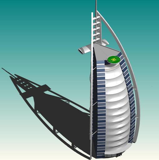
A scene containing a single distant light, and displaying shadow maps and a simple-shadow that both correspond to the light’s vector.
Limitations
The number of lights which can be displayed when shadow maps are enabled is limited to 4.
Ambient Occlusion
Ambient occlusion is a shading method which adds a photorealistic effect to local reflection models by taking into consideration light attenuation due to occlusion. Ambient occlusion requires global lighting calculations around every vertex of a model. The result is a soft shadowed appearance offering a better perception of the model’s shape. However, to achieve a good result, an additional operation that subdivides that model needs to be performed. Thus, these calculations become extremely expensive such that ambient occlusion becomes more suitable as part of the lengthy preprocess stage on a static model.
HOOPS simulates ambient occlusion in a more efficient way by processing the rendered images, including the z-buffer, instead of operating on the geometry directly. It applies a filter to search for small valleys in the depth buffer and then slightly darkens these areas. This operation is extremely low-cost computationally because it is unrelated to the size of the model. Thus it can be used on even the largest model. In addition to having little to no negative impact on performance, HOOPS’ approximation of ambient occlusion has no impact on the memory footprint of the model.
To enable ambient occlusion, call Set_Driver_Options and set “ambient occlusion” to on. The “ambient occlusion” option has a suboption called “strength” which lets you determine the overall darkening effect of the occlusion calculation. The code sample below shows how you can turn on “ambient occlusion” and set the strength to 2.
HC_Set_Driver_Options("ambient occlusion=(on, strength=2)");
|

|
|
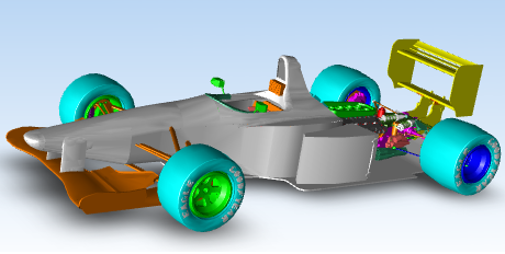
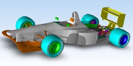
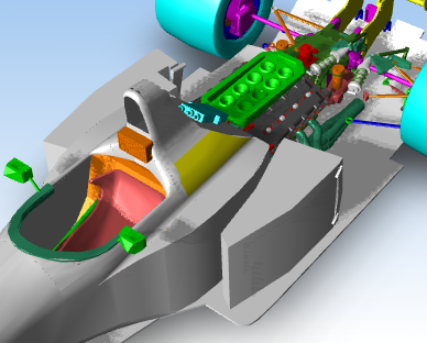
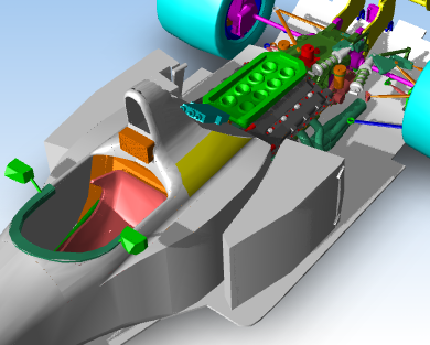
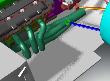
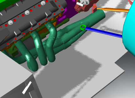
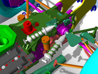
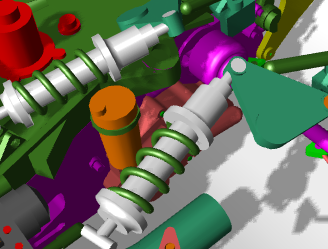
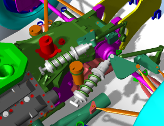
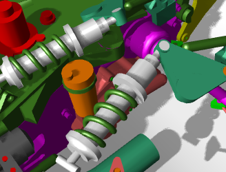
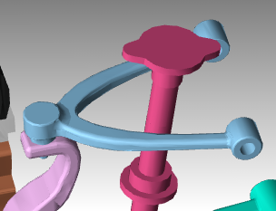
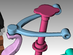
The figure shows three rendering of a wishbone suspension. The first image shows the model rendered with no ambient occlusion. To its right, ambient occlusion is turned on and the strength is left to the default value of 1. In the final image on the right, the model is rendered with ambient occlusion and the strength to 5.
In the figure above, we can see the understated effects of ambient occlusion especially in the center image. Dimpled areas, edges and regions where two or more surfaces meet are rendered with a slight shadowing. As a result, there is more of a sense of depth and realism in the scene.
If you turn lights completely off but keep ambient occlusion on, you can create a non-photorealistic shading effect commonly found in cartoon and other graphics media.
Please note that transparent geometry is unaffected by ambient occlusion.

