Shells
A shell is a collection of polygons that forms a 3D object. If the shell is closed, with no holes in it, then the shell divides 3D space into two parts called the inside and the outside of the shell. A shell consists of one or more polygonal faces. The advantages of using a shell, rather than using multiple independent polygons, are that the shell takes up less memory in the database, is considerably faster to render, can be smoothly shaded, and supports more advanced rendering capabilities such as texture mapping. A shell should be used to represent any 2D or 3D object that is described by a collection of polygons. For example, 3D surfaces or the boundary of solid objects are typically tessellated into a collection of polygons (usually triangles), hence a shell is the appropriate primitive. Shells are also typically used to represent common geometric objects such such as cubes, spheres, cylinders, etc…
Shell Geometry
You specify a shell using two arrays, an array of points called the point list, and an array of indices into the point array, called the face list. A separate array of points is used so that faces of the shell can share points with one another. For example, when you define a cube, each vertex is shared by four different faces, so you need only eight vertices to define six faces. If you defined the same cube using separate polygons (each with their own vertices), then each polygon would require storage for four points, for a total of 24 points stored in the database.
The face list is an array of integers. The first integer is the number of vertices in the first face, followed by an integer for each vertex, which are indices into the point array. For example, if the face list contains (3 0 1 2), then a triangle is formed from the first three points in the point array. The next entry in the face list starts another face, and so on.
Each face must be planar; in other words, all its vertices must lie in the same plane. In addition, the edges of a face must not intersect one another. Finally, all faces in a shell must have the same handedness; that is, the points must all be defined in the same direction (clockwise or counter-clockwise), viewed from outside the shell. Other than that, the definition of shells is flexible. The faces do not even have to be connected, edges can share more than one face, and faces can contain holes. Here is a simple example of the code you would write to create a cuboid of size 2 centered at (1, 1, 1) with a HOOPS shell primitive:
    int pcount, flist_count;
    pcount = 8;
    flist_count = 30;
    HPoint pts[8];
    int faces[30] = {4, 0, 1, 2, 3, 4, 1, 5, 6, 2, 4, 5, 4, 7, 6, 4, 4, 0, 3, 7, 4, 3, 2, 6, 7, 4, 0, 4, 5, 1};

    pts[0].Set(0, 0, 0);
    pts[1].Set(2, 0, 0);
    pts[2].Set(2, 2, 0);
    pts[3].Set(0, 2, 0);
    pts[4].Set(0, 0, 2);
    pts[5].Set(2, 0, 2);
    pts[6].Set(2, 2, 2);
    pts[7].Set(0, 2, 2);

    HC_KEY shellKey = HC_Insert_Shell(pcount, pts, flist_count, faces);
The HUtility class contains a method called InsertBox which creates a simple rectangular box centered around the origin using a shell. It first calls HUtility::GenerateCuboidPoints to obtain the vertices of the cuboid. Then it defines the face list and inserts a shell.
Using this routine, you can create a similar cube with the following code:
    HPoint min, max;
    min.Set(0.0f, 0.0f, 0.0f);
    max.Set(2.0f, 2.0f, 2.0f);
    HUtility::InsertBox(&min, &max);
Shell Attributes
Since shells are collections of polygons, they have the same attributes as polygons do. For example, you can change the face and edge colors of a shell, the face and edge pattern, the face and edge visibility, the edge weight, and so on. Shells also have several features that go beyond the capabilities of polygons:
- Vertex markers
- Silhouette/perimeter/hard/adjacent edges
- Cut edges/faces
- Attributes on subparts
- Smooth shading
- Advanced rendering
Vertex Markers
Like a polygon, a shell has faces and edges; in addition, the vertices of a shell can be represented by markers. You can change the marker symbol and size for these markers, and you can turn off the markers using two different commands. Calling Set_Visibility ("markers = on") will affect both the visibility of markers at shell/mesh vertices, as well as ‘regular’ markers (those denoted by Insert_Marker). Additionally, the markers drawn at shell/mesh vertices can be controlled by calling Set_Visibility("vertices = on"). Finally, calling Set_Visibility("markers only = [on/off]") controls just the ‘regular’ markers and has no effect on the ‘vertex’ markers.
For most uses of shells, it is common to turn off the visibility of markers. However, they can be useful in representing the shell data as a ‘point cloud’, providing highlight feedback during user selection, or providing ‘handles’ for the user to more easily select vertices.
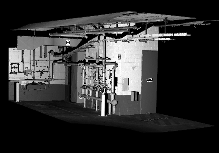
Vertex markers can also be used as point splats. In point splatting, large numbers of densely clustered points are rendered such that they appear as a smooth surface. When zooming in and out, the point splats scale accordingly continuing to give the impression that you are looking at a surface. This type of behavior is commonly used in laser scan datasets which consist of huge number of densely packed sampled points. In HOOPS, to use vertex markers for point splatting set your markers to scale with the object and camera via Set_Variable_Marker_Size. For point splatting to be effective, a large number of markers must be rendered in a scene. This can impact performance significantly, especially when zooming in and interacting with the object. HOOPS provides hardware accelerated rendering in this case via the Set_Driver_Options setting “marker drawing”.
By default, this option is set to “nicest”. To turn on hardware acceleration, set this option to fastest. In addition to setting this option, you must also ensure that your markers have either symbol [*] or (*) and that your variable marker size was set in wsu (world space units). Note that hardware acceleration is only available in the OpenGL2 and DX11 drivers. The following sample code shows how to set up vertex markers for hardware acceleration.
    /*Setting the vertex markers to be of variable size and in wsu*/
    float marker_size = (float)50 / 100;
    sprintf(tempstr, "%f wsu", marker_size);
    HC_Set_Variable_Marker_Size(tempstr);

    /*Setting the marker symbol to one of the two allowable symbols*/
    HC_Set_Marker_Symbol("(*)");

    /*Setting the Driver Option for Hardware Acceleration*/
    HC_Set_Driver_Options("marker drawing = fastest");
|
|
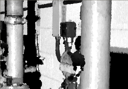
Shows a parking garage being rendered with point splats. The image on the left shows the scene zoom out to object extents. The image on the right show the scene zoomed in on the pipes with the individual splats more visible.
Additionally, you can improve performance by setting the “vertex decimation” rendering option. This option expects a value between 0.0 and 1.0 indicating the fraction of the vertices to be drawn. The fraction will be drawn from the front of the points array. As a result, the vertices need to be listed in a randomize fashion otherwise the point splat will not be rendered as expected. If your vertices are not pre-randomized, you can use the rendering option “randomize vertices” to cause vertices that are compiled into display lists to be inserted in random order. This option is intended for a more uniform point distribution when applying vertex decimation to non-randomized data.
3D Markers
HOOPS Visualize offers one 3D vertex marker that is tuned for use when rendering point clouds. The marker appears as a 3D Phong shaded sphere.
This marker is only for use in the shader drivers, and requires vertex lighting to be enabled (if vertex lighting is not enabled, it will appear as a flat circle). You can select this marker symbol in the following way:
HC_Set_Marker_Symbol("|*|");
HC_Set_Visibility("lights=(markers), markers=on");
In addition to specifying the marker symbol, setting visibility options will ensure your markers are visible.
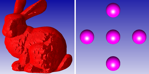
Demonstrating the effect of the 3D sphere vertex marker
Silhouette and Other Edges
The individual faces of a shell all have edges, and you can set the visibility of these edges on and off as usual. For a shell that is not a closed surface, you might want to see only the perimeter edges of the shell - those edges that are attached to only one face in the shell - and not to see the interior edges between two faces in the shell. You can tun on the visibility of perimeter edges with a special option of the Set_Visibility command:
HC_Set_Visibility("edges=(off, perimeters=on)");
This command turns off the visibility of edges, and then turns back on the visibility of perimeter edges, so that only they are visible.
Silhouette edges.
Another alternative is that you might want to display what are called interior silhouette edges. An interior silhouette edge is an interior edge (rather than a perimeter edge) that is visible in silhouette. An edge is visible in silhouette if one of its two attached faces is facing toward the viewpoint, and the other is facing away. Above, there are two interior edges, and one is a silhouette edge. All other edges are perimeter edges (they have only one attached face).
To make visible interior silhouette edges (as well as perimeter edges), you can use:
HC_Set_Visibility("edges=(off, perimeters=on, interior silhouettes=on)");
Rendered interior silhouette edges tend to be obscured by adjacent faces causing a stitching effect. HOOPS provides the ability to render silhouette edges with a different criterion with the “fast silhouette” setting in Set_Driver_Options. Fast silhouette edges are drawn where the difference between z-buffer values of neighboring pixels is greater than a certain threshold. You can determine the size of this comparison threshold via the “tolerance” suboption with values ranging from 0 to 100. As the name suggests, fast silhouette edges are hardware accelerated and take very few processing cycles as opposed to rendered interior silhouettes edges which can be computationally expensive to render. The following sample code shows how you can enable fast silhouette edges and set the tolerance level to 10. The intensity of silhouette edges are rendered based on how closed they are to the tolerance value. If you want all the exterior silhouette edges in your model to be rendered with an extra line to distinguish them, you can set the “heavy exterior” suboption to “on”.
HC_Set_Driver_Options("fast silhouette edges =(on,tolerance=10)");
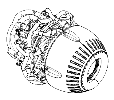
A turbine drawing rendered with fast silhouette edges. The model is rendered significantly faster with little loss of visual quality.
While the ‘perimeters’, and ‘interior silhouettes’ edge visibility options assist in the display of some key aspects of geometric data, they do not address the need to view ‘interesting’ edges of many datasets. Enabling the visibility of ‘hard’ edges will result in the display of edges whose coincident faces have an angle of intersection < 135 degrees (this is the default value; it can be controlled by calling Set_Rendering_Options("geometry options = (hard edge angle = <fff>")"). This results in the display of the ‘boundary’ or ‘feature’ aspects of a model. The ‘hard’ edge visibility setting would typically be used in conjunction with silhouettes and/or perimeters:
HC_Set_Visibility("edges=(off, hard, interior silhouettes)");
The above visibility setting produces particularly good results when used with the hidden-line removal algorithm, discussed here. There are other possible combinations for edge visibility. For more information, refer to documentation for Set_Visibility.
Finally, you can control the visibility of ‘adjacent’ edges, which are edges that are attached to at least one visible face.
In the vertex markers section, we discussed creating non-facetted shells also known as point clouds. Analogously, it might seem that you could create a shell with edges but no faces to gain better performance from a set of lines and/or polylines. However, we do not recommend this approach. Instead, the most efficient way to group and render lines and/or polylines is to use polycylinders. This method has a number of advantages including the ability to apply color interpolation which is not available for lines or polylines.
Cut Edges/Faces and Section Views
Cut edges and cut faces (sometimes referred to as cutting or capping geometry) denote the edges/faces of intersection between a cutting plane and the faces in a shell/mesh. They provide for display of a section view, which is typically controlled by allowing the user to move a cutting plane through the model, thereby ‘slicing’ it. You can turn on the visibility of cut edges and faces by setting:
HC_Set_Visibility("cut geometry = on");
The visibility of the cut edges and faces can also be independently controlled:
HC_Set_Visibility("cut geometry = (faces = on, edges = off)");
Cut edges/faces will only be calculated if one or more cutting planes exist and they are visible. The image below depicts a cone and a sphere that have been cut by a cutting plane and displays cut edges and faces:
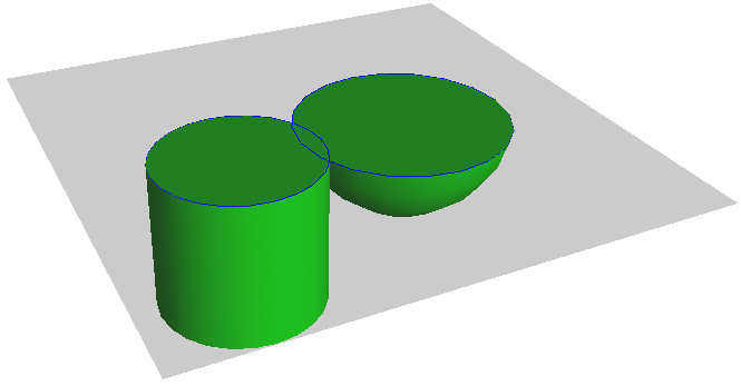
Cut edges and faces
It may also be desirable to control the color of the cutting geometry. Set_Color supports this:
    HC_Set_Color("cut faces = green");
    HC_Set_Color("cut edges = blue");
    HC_Set_Color("cut geometry = red");
The capping geometry generated by HOOPS is created and maintained in an area separate from the shells being cut. If you want a copy of the capping geometry generated by HOOPS, you can access it via Compute_Capping_Shell. This function takes as its parameters a list of shells and an array of floats that define the cutting plane. It returns one key that contains a copy of the generated capping geometry. This function requires that there is a currently open segment for it to insert the generated key. You can manipulate the capping geometry that was returned without affecting the capping geometry in scene because the returned geometry is a copy.
Attributes on Subparts
Unlike for the other kinds of geometry that we have seen so far, for a shell, you can set attributes on individual shells within a segment, as well as individual faces, edges, and vertices within each shell. This ability allows individual shells, and faces (and edges and vertices) in a single shell to have attributes completely different from one another.
To change the color on an entire shell, you first open the shell. Opening a shell is just like opening a segment, except that you must use a key (since shells are not named). Geometry is opened with the Open_Geometry command. Open geometry is closed with the Close_Geometry command. The following code sets the color attribute on a shell:
    HC_Open_Geometry(shellKey);
    HC_Set_Color("red");
    HC_Close_Geometry();
To change the color of a face, you first open the shell. Then, within matching open and close geometry commands, you can open an individual face, edge, or vertex, and can change its attributes. For example, you can open a face with the Open_Face command. The argument to Open_Face is the index of the face in the face list. For example, the following code sets attributes on the faces of a shell:
    HC_Open_Geometry(shellKey);
    HC_Open_Face(0); // open the first face
    HC_Set_Color("red");
    HC_Close_Face();

    HC_Open_Face(1); // open the second face
    HC_Set_Color("green");
    HC_Close_Face();
    HC_Close_Geometry();
Setting of attributes on individual faces in a shell.
This code opens the first face (index zero in the face list) in the cube, and sets that face’s color to red. It then opens the second face (index 1 in the face list), and sets the color to green. The other faces in the cube are not changed. If a face has not had a particular attribute set on it explicitly, that attribute is inherited from the regular segment attributes.
You can set any attribute on a face of a shell that you can set on the face of a single polygon, including the face color, face pattern, and visibility. You can also unset these attributes (for example, using UnSet_Color), and can show them (for example, using Show_Color), just like you would unset or show an attribute on a segment. There is a caveat regarding per-face textures and transparency. They are supported, but require creating a color map that contains the desired colors with its texture/transmission components, and calling HC_Set_Color_By_Index to set that color on a face.
You can also open an edge using the Open_Edge command. The arguments to Open_Edge are two numbers, which are indices into the points array of the currently open shell. There must be an edge between these two points. For example, the code snippet below opens the edge that is shared by the first and second faces of the cube (which happens to be the edge between points 0 and 1 in the points array).
    HC_KEY key = HUtility::InsertBox(point1, point2);

    HC_Open_Geometry(key);
    HC_Open_Edge(0, 1);
    HC_Set_Color("reddish green");
    HC_Close_Edge();
    HC_Close_Geometry();
Opening of an edge in a shell.
You can set (or unset, or show) any attribute on an edge of a shell that you can set on the edge of a single polygon, including the edge color, edge weight, edge pattern, and visibility.
Finally, you can open a vertex using the ::Open_Vertex command. The argument to ::Open_Vertex is an index into the points array. The following code sample marks each vertex of a cube with a different marker symbol.
    key = HUtility::InsertBox(point1, point2);

    HC_Open_Geometry(key);
    char const* symbols[8] = {"()", "(*)", "(x)", "(())", "(+)", "[]", "[*]", "[x]"};

    for (int i = 0; i < 8; i++) {
        HC_Open_Vertex(i);
        HC_Set_Marker_Symbol(symbols[i]);
        HC_Close_Vertex();
    }
    HC_Close_Geometry();
Opening of a vertex in a shell.
You can set any attribute on a vertex that you can set on a marker, including the marker symbol, marker size, marker color, and visibility.
Shells and Smooth Shading
One of the most significant capabilities that shells have (that goes beyond the capabilities of multiple polygons) is the ability to be smoothly shaded via lighting interpolation. Smooth shading, technically referred to as lighting interpolation, is described in the lighting interpolation section of the Programming Guide. There are two forms of smooth shading: Gouraud shading and Phong shading. Either can be applied to a shell.
Shells are drawn with Gouraud shading by default. By modifying the value of the “lighting interpolation” option within the Set_Rendering_Options command, you can disable smooth shading, specify whether shade either faces or edges, or use Phong shading. For example, to turn off smooth shading, use the following command:
HC_Set_Rendering_Options("no lighting interpolation");
Note that your scene must contain one or more lights if you want HOOPS to perform lighting interpolation.
HOOPS must be able to obtain a normal vector for each vertex in the shell. If you do not provide these normals, HOOPS will generate them by averaging the normal vectors for each face that shares that vertex. Even for simple shapes, such as spheres and cylinders, this average may not be realistic, and can produce lighting anomalies. To avoid this problem, you can set normal vectors explicitly using Set_Normal. The Set_Normal command is unusual in that it is valid only inside of an open face or vertex; it cannot be applied to a segment.
For the purposes of smooth shading, it is best to set normal vectors on the vertices, but you can also set normal vectors on the faces or edges of a shell, and HOOPS will average these normals to obtain the vertex normals for smooth shading. Alternatively, you can set the edge color or face color on an open vertex, and HOOPS will use these color values directly for color interpolation.
You can also unset a normal (so that it will go back to being calculated by HOOPS), and can show the value of the normal. The ::Show_Net_Normal command returns the value you have set, or, if you have not set a value, returns the calculated value that HOOPS will use for that normal (there is no “inherited” value for a normal). The value returned by Show_Normal or Show_Net_Normal may not agree exactly with a value that you set because of normalization (normalizing a vector keeps it pointing in the same direction, but sets its length to 1.0). To get the normal value for a specific face and vertex, use MShow_Face_Normals and MShow_Vertex_Normals, respectively.
Advanced Rendering
In addition to performing lighting interpolation (smooth shading), HOOPS/3dGS supports a variety of other rendering techniques for shells, including :ref:color interpolation <prog_guide/3dgs/06_3_rendering_lighting_and_color_interpolation:Color interpolation>`, transparency, fog, and texture mapping </prog_guide/3dgs/05_2_materials_texture>.
The MSet Verb
Setting attributes on individual vertices and faces can be tedious and slow, so HOOPS provides a special verb to set individual attributes on multiple vertices and faces at the same time.
For example, you can set all the normal vectors in a shell from an array of vectors with MSet_Vertex_Normals. You can also set the vertex/faces colors (using either MSet_Vertex_Colors_By_FIndex, MSet_Vertex_Colors_By_Value, MSet_Face_Colors_By_FIndex, and MSet_Face_Colors_By_Value) and texture-map vertex coordinates (using MSet_Vertex_Parameters).
The visibility attribute can be set on specific faces using MSet_Specific_Face_Visibilities, MShow_Specific_Face_Visibilities and ``MUnSet_Specific_Face_Visibilities. It can also be set on specific vertices using MSet_Specific_Vertex_Visibilities, MShow_Specific_Vertex_Visibilities, and MUnSet_Specific_Vertex_Visibilities. To set visibility for individual edges use ``MSet_Specific_Edge_Visibilities, MShow_Specific_Edge_Visibilities, and MUnSet_Specific_Edge_Visibilities.
Editing a Shell
A shell can be large, containing hundreds or even thousands of faces. If an application is making incremental changes to a shell, it will be far too expensive to require the entire shell to be deleted and then reinserted into the HOOPS database after each change. Instead, you can make changes to a shell while it is in the HOOPS database, using the commands Edit_Shell_Faces and Edit_Shell_Points. A common use of these commands is to allow interactive editing of single points in a shell - to allow a user to grab a point on a shell and to move that point into a new position.
To edit a shell, you might need to find out the current contents of the shell. You can get this information with the Show_Shell and Show_Shell_Size commands. You use the Show_Shell_Size command to find out the sizes of the point list and face list, so arrays can be allocated for them. For example, use
    int point_list_size, face_list_size;

    HC_Show_Shell_Size(key, &point_list_size, &face_list_size);

    Point* point_list = new Point[point_list_size];
    int* face_list = new int[face_list_size];

    HC_Show_Shell(key, &point_list_size, point_list, &face_list_size, face_list);
You can also use Show_Partial_Shell and Show_Partial_Shell_Size to retrieve part of a shell. For example, you can find out the value of a single point in the shell with the following command:
    Point the_point;

    HC_Show_Partial_Shell(key, which, 1, &the_point, 0, 0, 0, 0);
The first argument is the key of the (previously inserted) shell. The second argument is the index of the point to be returned. The third argument is the number of points to return in the fourth argument (in this case, just one). The final four arguments return faces from the face list; in this case, they are not used.
Finally, there are two routines to delete arbitrary faces/points in a shell. See Delete_Specific_Shell_Faces and Delete_Specific_Shell_Points.
Tristrips
A list of tristrips (strips of triangles) are generated when a shell is first rendered, and those tristrips are sent to the device for drawing. Use of tristrips ensure maximum rendering performance. If tristrip information for the shell already exists, a variant of the shell insertion routine can be used called Insert_Shell_By_Tristrips and the tristrips can be queried by calling Show_Shell_By_Tristrip.
Tristrip Recalculation
HOOPS/3dGS will automatically re-tristrip a shell after an edit is made. A system option called “restrip on edit” (set by calling Define_System_Options) is available to control this behavior. Setting “restrip on edit = off” instructs HOOPS/3dGS to not recalculate shell tristrips after shell point arrays have been edited. This allows the modified version of the shell to be re-drawn very quickly, and is particularly useful when animating data. This option should be set if only the point locations change. If the topology changes (which would include adding/removing points, or causing a shell face to go from concave to convex or vice versa) and this option is set at the time of the edit, then the visual correctness of the shell is not guaranteed.
Trifans
Tri-fans can also be specified when using Insert_Shell_By_Tristrips. HOOPS/3dGS will pass these through to OpenGL. However the HOOPS internal triangle algorithms do NOT support tri-fan generation. For detailed usage information, refer to the HOOPS/3dGS Reference Manual entry for Insert_Shell.
Regions
MCAD datasets frequently include topology data structures such as ‘bodies’ and ‘faces’. A ‘body’ typically represents a discrete object (like a phone face plate or an engine cylinder), while a ‘face’ in this context represents a subpart of the body (the indented/curved parts of the phone faceplate, or the inside and outside of the cylinder.) Note that a topological-face is not to be confused with a shell-face. (A shell is comprised of n-sided facets, each of which is also called a face.) The most efficient way to represent a body in HOOPS/3dGS is to use a single shell for each body (discussed further in the performance section). However, it may be desirable to select on or modify the display properties of a subset of the shell that corresponds to a particular face. Regions make this easy.
A region is a user-defined collection of facets within a shell and thus can be used to represent a topological-face. You can select and set attributes individually on a region, thereby providing granular shell access without incurring the rendering performance hit or increased memory usage that would result from using a single shell for each face.
Defining Regions
Let’s take the case of a cube that represents a single body, and each side represents a region. We would insert a single shell that represents the cube and then setup the regions. There are two ways to achieve this:
- Open a shell face and then call
Set_Region, which adds the currently open shell-face to the specified region:
    HC_Open_Geometry(shellKey);
    HC_Open_Face(face_id);
    HC_Set_Region(region_id);
    HC_Close_Face();
    HC_Close_Geometry();
MSet_Face_Regions can be used to set the range of faces to a list of specified regions.
- Open a region and then call
Set_Faces, which adds a list of faces to the currently open region:
    HC_Open_Region(region_id);
    HC_Set_Faces(first_face_id, face_count);
    HC_Close_Region();
MSet_Region_Faces can also be used to add a range of faces to the specified region.
Querying Regions
To query what faces belong in a region, open the region and call Show_Faces (You will need to first call Show_Faces_Count to determine how much memory to allocate since Show_Faces will return an array.) Conversely, if you have a shell face id, you can find out the region that it belongs to by calling ::Show_Region (you must first open the shell-face with ``Open_Face). This could be used to determine what region was selected after the user picks on a shell. (The HOOPS/3dGS Show_Selection_XXX routines return the id of the closest vertex, edge and [shell]-face in a shell.)
Creating a New Shell From a Region
In review, various attributes can be set locally on a region since it is just a grouping of shell faces, and shells support several local attributes. They include color, visibility, face pattern. However, it may be desirable to set other non-local attributes on a region such as texture, transparency setting, or modelling matrix (in order to move the region). This would require that the region’s faces be part of a new shell that resides in a segment with different attributes. The function ::Insert_Shell_From_Region makes this easy. It creates a new shell containing only the points and faces (and any associated attributes) contained in the specified. Temporarily changing attributes of a region could be done via the following steps:
- Make a new shell from the region.
- Make the original region invisible.
- Change attributes as desired on the new shell.
- When done, delete the new shell and unset the region visibility (making it visible again).
Compute_Boolean_Shell
Most applications use a dedicated solid modeller toolkit to perform boolean operations on solid objects. However, there is benefit in a graphics toolkit being able to ‘simulate’ such operations on the facetted surface of objects. While the calculation isn’t precise (since we start with a facetted approximation of the parametric surface), there is no need for a solid modeller; the calculation is also faster. HOOPS offers this alternative with the Compute_Boolean_Shell function.
Compute_Boolean_Shell performs a boolean subtract, union, or intersect between two shells. You pass in the points/face-list/normals data representing the ‘target’ and ‘tool’ shells, and then are returned a key to the resulting shell. Note that this is an imprecise calculation. The resulting shell of Compute_Boolean_Shell may contain a disproportionate number of triangles in the region where the target and tool meet. If the boolean functionality is used for continuous surface removal, this effect may become compounded.
Additionally, due to the nature of the algorithm, occasionally very small triangles will be created which can lead to precision problems, such as missing faces or faces with incorrect handedness. In extreme cases, these precision issuescan lead to the creation of extraneous triangles.
Sample Primitives
As previously mentioned, shells are typically used to represent analytic objects such as spheres, cones and cylinders. This requires calculating the shell’s points array and face list based on the equations for these objects. This is demonstrated in the HOOPS/MVO class called HUtilityGeometryCreation defined in HUtilityGeometryCreation.h, and its implementation is contained in HUtilityGeometryCreation.cpp. The class contains routines to create spheres, cones, cylinders and cuboids. The routines utilize a local utility function called GeneratePointsOnCircle to generate multiple points along a circle based on a center point and a radius. These classes also reference members of the HUtility class.
The geometry creation functions will create the object such that it is oriented along the Y-axis by default, but they also take some special arguments to allow for the object to be oriented along an arbitrary axis. This involves some vector math to compute the value of a modelling matrix that is manually set in the HOOPS/3dGS segment containing the object. Details on modelling matrices are discussed later in the viewing section.

