HOOPS RealDWG Integration
Using the RealDWG HIO Component
The native RealDWG libraries supplied by Autodesk are required to read and write DWG and DXF files. To use HOOPS Visualize with the HOOPS/HIO module, developers are required to license the RealDWG Toolkit. Please contact a Tech Soft 3D representative for licensing details. The release notes Library Compatibility Information indicates the version of RealDWG compatible with a given version of HOOPS Visualize.
To use the HOOPS/HIO component for RealDWG, please follow the steps below:
- Create a hio_plugins directory in your application’s working directory.
- Copy the hio_dwg.hio file found in /bin/<platform>/hio_plugins/hio_dwg to the hio_plugins directory created in the previous step.
- Ensure that the RealDWG SDK is installed on your system and in your path.
- Copy all DBX and DLL files from the RealDWG directory to your application’s working directory.
- Copy the en-US folder from the RealDWG directory to your application’s working directory.
- Run your application.
During start-up, when HOOPS/MVO finds the RealDWG HIO component in your application’s path, it will perform the following steps:
- Load in the necessary RealDWG libraries.
- Create the appropriate input handler.
- Register this handler and the associated file extensions to the
HIOManager.
To utilize the extensive services available in the RealDWG toolkit, you must compile against the RealDWG libraries directly and follow the steps described in Integrating directly with RealDWG.
Unsupported Entities
All entities found in RealDWG are supported by HOOPS Visualize except for:
AcDbWipeOut- Custom line pattern
DWG Units
When a RealDWG model is imported into HOOPS Visualize, the model units are also imported. As of HOOPS Visualize version 19.01, this information can be found in the “model_information” segment under the model key as a Visualize User_Option called “cad units”. For example, if the user option value is “cad units =Inches”, this means that one unit length of the imported entity is equivalent to one inch. The possible units are as follows:
- Inches
- Feet
- Miles
- Millimeters
- Centimeters
- Meters
- Kilometers
- Microinches
- Mils
- Yards
- Angstrom
- Nanometers
- Microns
- Decimeters
- Dekameters
- Hectometers
- Gigameters
- Astronomical
- Light Years
- Parsecs
- Undefined Units
For backward compatibility with HOOPS Visualize versions prior to 19.01, the DWG units information is also stored in a segment underneath the model key, called “info”, and is stored in the “dwg_unit” user option.
DWG Font Handling
During the import of a DWG that contains text, any fonts specified in the DWG file must be on the system because fonts can not be embedded in a DWG file. If the importer does not find the given font, the text will be drawn with the default HOOPS Visualize font. This behavior can be modified using Set_Text_Font.
Integrating Directly with RealDWG
The RealDWG HIO component allows developers to easily import visualization information into the Visualize database. However, DWG files also contain more than just visualization information. If your application needs to access or manipulate the extensive information found in DWG files or utilize the full range of the RealDWG library services, you will require a tighter integration than what the RealDWG HIO component can provide - you need to integrate directly with RealDWG. To do so, follow these steps:
Install the RealDWG toolkit on your system.
Set an environment variable which points to the root of your RealDWG installation.
With msvc toolset v142 REALDWG_XXXX_SDK_DIR_X64 = REALDWG_2023_SDK_DIR_X64 With msvc toolset v143 REALDWG_XXXX_SDK_DIR_X64 = REALDWG_2025_SDK_DIR_X64
Add files HIOUtilityDWG.h/.cpp and HDWGHelper.h/.cpp to your project. These files are located in the Dev_Tools/hoops_hio/hio_dwg/source directory of your HOOPS Visualize installation.
Add the following directory paths to your additional include folders’ list $(REALDWG_XXXX_SDK_DIR_X64)/include.
Add $(REALDWG_XXXX_SDK_DIR_X64)/lib to your additional linker directories.
Add the following files as additional dependencies:
With msvc toolset v142 <xx> = 24 With msvc toolset v143 <xx> = 25
- ac1st<xx>.lib
- rcexelib.obj
- acgiapi.lib
- acdb<xx>.lib
- acge<xx>.lib
- rxapi.lib
- acismobj<xx>.lib
- odbc32.lib
- odbccp32.lib
- urlmon.lib
- wininet.lib
Ensure that the
REALDWG_XXXX_SDK_DIR_X64environment variable is in your path.
Once you have completed the above steps, you do not need to rely on the RealDWG HIO component anymore. Please remove the associated .hio file from the hio_plugins directory in your application’s working directory. Note that in a direct integration with HOOPS Visualize, you must register the DWG handler``HIOUtilityDWG`` via HIOManager::RegisterInputHandler so that the HBaseModel::Read function can recognize that the .dwg file format. For more information on HOOPS/MVO file input/output architecture, please see section File Input/Output and the I/O Manager of the HOOPS/MVO Programming Guide.
Now you can begin working with HIOUtilityDWG class which is HOOPS/MVO’s input handler for RealDWG. The next section demonstrates how to instantiate the input handler and import a DWG file.
Importing a File
The process for importing a DWG file is similar to the process for importing other file types through the HIO interface. For example, to import DWG data into the model segment, you could use the following code:
HInputHandler * dwg_handler = HDB::GetHIOManager()->GetInputHandler("dwg");
if (dwg_handler)
{
        HInputHandlerOptions opts;
        char texture_directory[] = "/path/to/textures";
        opts.m_pExtendedData = (void *)texture_directory;

        // import DWG file into model segment
        HFileIOResult result = dwg_handler->FileInputByKey("filename.dwg", m_pHView->GetModelKey(), &opts);
        if (result == HIO_OK)
                // file loaded OK
        else
                // handle error
}
else
        // handle error
Although it is possible to recompile the HIO RealDWG input handler, you can only have one RealDWG handler in your application. If you compile a second handler, you should delete the old one - otherwise, the behavior is undefined.
The sample above includes an optional path to the texture directory, which contains any image files used to generate textures. In a typical installation, this directory would be set to C:\Program Files (x86)\Common Files\Autodesk Shared\Materials.
Alternatively, if you didn’t want to set a texture directory, you could simply call \ref FileInputByKey() with a NULL parameter instead: FileInputByKey("filename.dwg", m_pHView->GetModelKey(), NULL);.
Mapping Between HOOPS/3dGS and DWG Entities
The RealDWG Scene Graph
Upon import, the HIO RealDWG component will create the following scene graph:
- root import segment
- block table
- master
- *<block table name>* - a subsegment for each block table record. Segment names correspond to block table names in AutoCAD, but sanitized. HIO RealDWG will prepend btr_ to the name, characters are converted to lowercase, and finally it will be URI encoded. We also enclose the name in back-ticks if the name has special characters. Thus, a name like *Model_Space becomes `btr_%2model_space`.
- geometry - contains the geometric definition of the entity
- *<block table name>* - a subsegment for each block table record. Segment names correspond to block table names in AutoCAD, but sanitized. HIO RealDWG will prepend btr_ to the name, characters are converted to lowercase, and finally it will be URI encoded. We also enclose the name in back-ticks if the name has special characters. Thus, a name like *Model_Space becomes `btr_%2model_space`.
- xrefs - only present if the DWG file contains external references. The subsegments are URI encoded and they represent the block table recrods from the external file.
- master
- layer table
- *<layer names>* - taken from layer names in the DWG file. HIO RealDWG will prepend the name with and underscore, then convert it to lowercase.
- handles - see "Entity mapping" subsection below for notes about handles
- info - contains a USER OPTIONS value called "dwg_units". This indicates the scale of the model. For example, "dwg_units=Centimeters" indicates the model units are centimeters.
- layouts
- *<layout names>* - one subsegment for each DWG layout. Names are sanitized like layer names. By default, we always display the "_model" layout. To change layouts, turn visibility off for the segment, then on for the layout segment you wish to change to. Additionally, remove the heuristic "exclude bounding", and enable it for the segment you wish to change to.
- viewport table - currently unused
- xdata - see related section below
- block table
Entity Mapping
Each DWG entity has a unique handle associated with it. The handle is unique within the database, and is the same session after session. The handle is represented by an unsigned 64-bit integer. Handles exhibit the following relationships:
- One DWG handle corresponds to one or more HOOPS Visualize keys.
- One Visualize key corresponds to only one DWG handle.
- Two different DWG handles cannot refer to the same Visualize key.
When associating handles to keys, keep the following in mind:
- every time a piece of Visualize geometry is inserted, it is opened by key, and a user option containing the DWG handle identifier this piece of geometry belongs to is set on it.
- a segment called “handles” is created during import and placed directly under the MVO model segment.
- as geometry is read in, a reference to it is placed in a subsegment of the “handles” segment, named after the DWG handle the geometry belongs to.
To relate a DWG handle to a HOOPS Visualize key, you would do the following:
Case A - You have a HOOPS Visualize key and wants to obtain the related DWG handle:
- Open geometry by key
- Use
Show_One_User_Datato read the data stored at index 0 - The data returned by
Show_One_User_Datawill contain the DWG handle.
Example:
Adesk::UInt64 handle;
HC_Open_Geometry(key);
HC_Show_One_User_Data(0, &handle, sizeof(handle);
HC_Close_Geometry();
Case B - You have a DWG handle and want to obtain the related HOOPS Visualize key(s):
- Open the “handles” segment and search for the segment whose name matches the DWG handle.
- Search the segment for reference geometry, and obtain its original key
Using a Hash to Improve Speed
Starting with Visualize 19.33, the developer has the option to query DWG handles in an optimized way. The process described in the previous section will always work, however, for large scene graphs, the processing time can be long. Using the HIO connector to associate DWG handles to Visualize keys is faster because it uses a hash lookup instead of searching the segment tree. There is a performance penalty, however, when the hash is generated.
This is how to obtain a connector:
HInputHandler * handler = HDB::GetHIOManager()->GetInputHandler("dwg");
handler->FileInputByKey("filename.dwg", view->GetModelKey(), options);
HIOConnector * connector = HDB::GetHIOManager()->CreateConnector("dwg");
All the associated functions (see list, below) have an optional parameter at the end. Passing the model key as that parameter causes the hash to be generated (or regenerated, if the geometry has been modified). Therefore, the first time you use this hash, you should always pass the model key.
The DWG connector can use the following functions:
HC_KEY GetHoopsEntity(void * pKernelEntity, HC_KEY modelKey = INVALID_KEY);
This function returns a HOOPS Visualize key associated with a DWG handle. Causes hash to be regenerated. Sample usage:
unsigned int handle = 570;
HC_KEY key = connector->GetHoopsEntity((void *)handle, view->GetModelKey());
void * GetKernelEntity(HC_KEY key, HC_KEY modelKey = INVALID_KEY);
This function returns a DWG handle associated with a HOOPS Visualize key. Causes hash to be regenerated. Sample usage:
void * kernelEntity = connector->GetKernelEntity(key);
bool GetHoopsEntities(void * pKernelEntity, vlist_s *ret_HoopsKeysList, HC_KEY modelKey = INVALID_KEY);
Same as GetHoopsEntity, but is used in the case when a DWG handle is associated with more than one Visualize key. Causes hash to be regenerated. Sample usage:
vlist_s * hoopsKeyList = new_vlist(malloc, free);
connector->GetHoopsEntities((void *)myHandle, hoopsKeyList);
void * item  = vlist_nth_item(hoopsKeyList, 0);
void * item2 = vlist_nth_item(hoopsKeyList, 1);
bool GetKernelEntities(HC_KEY key, vlist_s *ret_KernelEntitiesList, HC_KEY modelKey = INVALID_KEY);Same asGetKernelEntityvoid AddConnection(HC_KEY key, void* pKernelEntity, HC_KEY modelKey = INVALID_KEY);. Adds a connection between a key and a handle. Does not cause the has to be regenerated.
Layers and Layouts
Layers are treated as attribute containers. Whatever attributes are in the layer are applied to the geometry with a HOOPS Visualize style. This means that you can open the layer segment and override the attributes. If the geometry has attributes set on it explicitly, then the explicit attributes override the layer attributes. There’s a case when the attributes of geometry are inherited from the block reference. Those attributes cannot be overridden by the layer. The layers can be found in the segment “layer table”. The layers are URI encoded, to allow unicode characters in the segment names, and are prefixed with an underscore ‘_’ character.
Layouts can be found in the “layouts” segment. The layouts are also URI encoded and prefixed with an underscore. Each layout has user options, “extents_min” and “extents_max” set defining the extents in 2D space. Each layout also sets the heuristic “exclude bounding” and sets the visibility to “off” except for the currently active/visible layout. The currently active/visible layout does not set visibility and does not set the exclude bounding heuristic. Iterating the visibility of the layouts is done by finding the layout that does not set the visibility, then setting the visibility to off, setting the exclude bounding heuristic, then moving on to the next layout segment and unsetting the visibility and unsetting the heuristics.
Object Enablers
HIO DWG allows developers to use object enablers. Using object enablers, customers can load DWG files which contain custom entities defined in their own .dbx files.
The only requirement for this to work is that the developer must place the .dbz files and associated DLLs into the same folder as the HIO DLL, so that they can be loaded when DWG starts up.
Handling Metadata
Each DWG entity may have associated XDATA. The DWG standard calls metadata XDATA. Metadata can be of any type. If a DWG file contains metadata, HOOPS Visualize will create a subsegment under the main DWG model segment called xdata. The xdata segment will contain subsegments that correspond to metadata stored in the file. The name of each subsegment corresponds to the value of the DWG entity handle to which the metadata applies. The image below shows an example segment tree showing the xdata segment and subsegments which contain metadata.
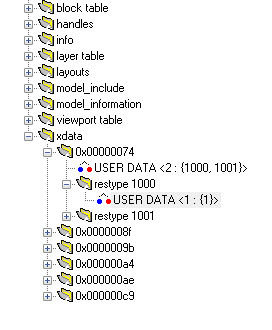
The subsegment 0x00000074 indicates the metadata in this segment belongs to DWG entity with the same handle value. In this case, USER DATA indicates that there are two types of metadata present for this entity. These types are 1000 and 1001. The child segment “restype XXXX” contains the metadata values themselves. For an example of how to read metadata from an XDATA segment tree, see the code sample in get_xdata.cpp <examples/get_xdata.cpp>.
Limitations
Dimensions, Annotations, and Layouts
It is possible for a DWG file to be stored with uninitialized annotations and layouts. These uninitialized structures don’t always exist in the DWG file. In this situation, RealDWG returns them as null pointers. Using its own internal logic, AutoCAD is able to load the uninitialized structures from null pointers, however, RealDWG cannot. Therefore, we do not support uninitialized annotations or layouts.
Viewports
Viewports within layouts can be in an ‘active’ or ‘inactive’ state. RealDWG doesn’t provide any mechanism to find which viewports are active.
Rendering
Although we make every effort to duplicate the rendering results of any file loaded using RealDWG, Visualize cannot exactly match AutoCAD in all cases when it comes time to actually draw. AutoCAD uses its own proprietary rendering engine that handles geometry in its own way. Some examples of differences we have noticed include:
- tessellation values
- line weights and line styles
- font handling
Incorrect Linetypes in Some Cases
Occassionally, RealDWG will incorrectly read a linetype. For example, a line may appear continuous when it really should appear dashed. This is a confirmed bug in RealDWG recognized by Autodesk. The bug happens because the DWG libraries will cull details in order to optimize a drawing when the view distance is sufficiently far. However, when loading a file, RealDWG incorrectly provides the culled version of the entity instead of the actual verion.

