Hidden Surface Removal
Hidden-surface removal refers to removing objects (or parts of objects) that are hidden from the viewpoint by other objects, which ensures that the scene looks correct. This process involves the use of a hidden-surface removal algorithm. In HOOPS/3dGS, you can choose from a number of hidden-surface removal algorithms. Which one is best (executes fastest, and gives the most realistic images) will depend on the hardware you have and the specific result that you’re looking for. Algorithms supported by HOOPS include hardware Z-buffer, software Z-buffer, painter’s, Z-sort, priority, and hidden line. The HOOPS/3dGS routine Set_Rendering_Options allows you to specify the hidden surface removal algorithm by setting the “hsra” rendering option. For example:
HC_Set_Rendering_Options("hsra = hardware z-buffer");
Do note that it may not even be necessary to perform hidden surface removal, such as a wireframe scene (‘edge’ and/or ‘lines’ are visible but ‘faces’ are not), or if you are in a 2D scene. You control whether hidden surface removal is performed by setting the “hidden surface” heuristic:
HC_Set_Heuristics("no hidden surfaces");
The most common rendering scenarios are discussed below.
2D and Wireframe Scenes
A 2D scene refers to a scene where everything is drawn in the same plane. The z component of each point in each geometric primitive may not necessarily be zero, but is equal. In this case, there is typically no reason to perform a hidden surface calculation, since nothing is ‘in front of, or behind, anything else. There is a caveat to this, such as the case where you may need to specify a particular drawing order of the primitives, even though they may have the same (z=0) values. This is common when dealing with CAD drawings where entities are meant to be drawn on specific layers. See this section, for info on how to control drawing order for such scenes.
A wireframe scene, regardless of whether the data is 2D or 3D in nature, is similar; it implies that only edges or lines are visible, and faces (which represent surfaces) are not visible. Therefore, there is generally no need to perform a hidden surface calculation. As implied above, if you set the “no hidden surfaces” heuristic, it doesn’t matter what hidden surface removal is set, because hidden surface calculations won’t be performed.
Using Hidden Surfaces with 2D/Wireframe Scenes
There may be situations when it is desirable to perform hidden surface removal in 2D or wireframe scenes. In a wireframe scene, you may want to have the wires (edges/lines) of objects be drawn ‘accurately’ with respect to one another. This would require turning on hidden surfaces.
For 2D scenes, it’s possible that the 2D vectors and/or polygons have some ordering to them, where some should be drawn on top of others. One way to address this is to add a 3D ‘fudge factor’ to the data and turn on hidden surfaces, so that geometry will be drawn in a certain order. However, a better solution to this issue may be to manually control drawing order by setting the “no hidden surfaces” Heuristic and using Bring_To_Front as discussed in this subsection.
3D-Scenes
By a 3D scene, we mean one which contains 3D facetted data, and the faces are visible. Therefore, the picture will only look correct if a “hidden surface removal” calculation is performed. The following algorithms are supported by HOOPS/3dGS:
Z-buffer
The Z-buffer algorithm uses a large block of memory consisting of one word for every pixel in the frame buffer. This memory is initialized with a number larger than the largest z value of any object to be drawn. To render an object, we calculate the pixels that make up the object. Before each pixel is written into the frame buffer, the depth (distance from the viewpoint) of that pixel is compared against the current value for that pixel in the Z-buffer. If the new pixel is closer, its color value is written into the frame buffer, and its depth is written into the Z-buffer. That way, we write only those pixels that are closer than any object already written into the frame buffer.
The main advantage of the Z-buffer algorithm is speed, especially when the algorithm is implemented in hardware. A secondary advantage is this algorithm can handle curved surfaces, such as NURBS patches. In the curved surface shown below, the same pixel (indicated by the small square) intersects the surface three times. In the painter’s algorithm, we would have to subdivide the surface into three pieces; that subdivision is difficult to do (and is computationally expensive). The Z-buffer algorithm just renders all the pixels of the surface, and the closest surface at each pixel will be displayed.

A curved surface hiding itself.
The Z-buffer algorithm in hardware is the best choice when rendering to the screen. HOOPS/3dGS provides support for both hardware and software Z-buffer algorithms. The software Z-buffer uses the same algorithm as the hardware Z-buffer option except that all calculations are done in software using a 32-bit software Z-buffer. The default algorithm is hardware Z-buffer; if it is not available, then the painter’s algorithm will be used. If one of the HOOPS/3dGS 3D driver interfaces is being used, then hardware Z-buffer will work correctly. If a non-3D driver is being used (such as the HOOPS/3dGS Windows GDI driver), then the software Z-buffer is the probably the best choice.
Painters
The painter’s algorithm is so named because it works like opaque paint - objects painted later cover up earlier objects. All the objects in a scene are sorted in order of their distance from the viewpoint, with the farthest object first. Then, they are rendered in depth order. As each object is rendered, it covers up any object that is farther away. The painter’s algorithm has a problem in that it assumes that each object has a single distance from the viewpoint. If an object is not parallel to the screen, then its distance from the screen is actually a range of values. It is possible for several objects to overlap such that there is no ordering that will result in them being rendered properly. In this case, it is necessary to split one or more of the objects into smaller pieces.

Three objects that overlap in depth.
Z-Sort
The Z-sort algorithm is a faster variation of the painter’s algorithm. It assumes that objects never overlap in depth, so they never have to be split. Z-sort is useful when high rendering speed is more important than is an occasional mistake in hidden-surface removal.
Priority
Using Set_Priority() values with “hsra=priority” to control drawing order of specific pieces of geometry:
If the “hidden surface removal algorithm” rendering option is set to “priority” HOOPS will render the scene based on the Set_Priority() value applied to geometric primitives.
This is useful in a case where we want all geometric primitives to be drawn in a specific order, relative to one another. Typically this would be used in a case where we’re dealing with a 2D drawing and all primitives have z=0.
If you have 2D scenes and want to ensure maximum performance, be sure to follow some key guidelines:
Group primitives into as few segments as possible based on similar attributes
Set the “segment level display lists” rendering option
If the primitives are all 2D (i.e. z=0) but require a specific drawing order:
- apply a priority to each primitive, using
Set_Priority() - set the “hidden surface removal algorithm” to “priority”.
- apply a priority to each primitive, using
If the “no hidden surfaces” heuristic is set, HOOPS will render the scene based on the Set_Priority() value applied to sibling segments.
This is useful in a case where we want all the contents of a particular segment drawn in a specific order relative to the contents of another sibling segment. This may be useful in cases where a 2D drawing, and we want to order entire layers in the drawing.
For example, if two sibling segments are being used to represent Layer A and Layer B and it’s desirable to have everything in Layer A get drawn in front, you would set a priority of 1 on Layer B, and a priority of 2 on Layer A (B gets drawn first, A gets drawn last). Since we have “no hidden surfaces”, the z-values of the geometry are ignored.
Note that in this “no hidden surfaces” case, a priority value has NO effect on geometry. It only affects segments.
Be sure to read the Reference Manual entry on the “priority” hidden surface removal algorithm in detail.
Hidden Line Removal
Hidden line removal involves displaying only visible (i.e. unobscured) lines or parts of lines. The visibility of lines must be set to “on”. Faces of geometry which have a visibility setting of “faces=on” will be used to obscure lines, markers and text.
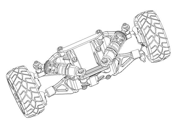
A suspension system rendered with hidden line removal.
However, it may be useful to display faces in certain situations. For example, if the scene contains arrowheads or text, the user will probably want to see ‘filled’ versions of these objects rather than just their outlines. To force display of faces during an HLR rendering, you can set “hlr options” to “render faces”:
HC_Set_Rendering_Options("hlr options = render faces");
HLR Algorithms
Two hidden line removal algorithms are supported. One of them is an analytic algorithm which is more accurate, but is of O(n log n) complexity and can be computationally intensive depending on the amount of geometry in the scene. This is because it needs to clip all visible lines, text and strings against all visible triangles. Triangles are placed into a quad-tree to speed up the clipping process. The insertion points of text and markers are used during the clipping process. This algorithm is enabled by setting the “hidden surface removal algorithm” in the following line:
HC_Set_Rendering_Options("hsra = hidden line");
The other algorithm is Z-buffer based and thus is of O(n) complexity. This allows it to be used during interactive viewing. It works on all 3D drivers. HOOPS/3dGS will fall back to analytic hidden line if the current driver does not support Z-buffer, or if HOOPS finds a driver implementation that doesn’t support the required features. A way to combine the use of the two algorithms would be to use the fast algorithm for visual display, but use the more accurate analytic algorithm for hardcopy output. The fast algorithm is enabled by setting the “hidden surface removal algorithm” to ‘fast hidden line’:
HC_Set_Rendering_Options("hsra = fast hidden line");
Note: “zhlr” is a synonym for “fast hidden line”.
The “fast hidden line” algorithm can be used with a combination of “render faces” and object transparency to provide a hybrid rendering showing HLR, hidden lines and shadows.
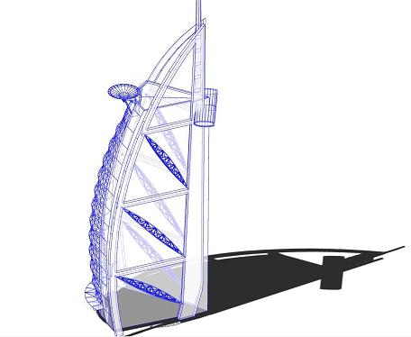
A structured displaying a hybrid rendering of HLR, hidden lines and shadows.
The above sample image can be produced with the following attribute combination:
    // Set the window background color equal to the face color, and enable transmission
    HC_Set_Color("windows = white, faces = (diffuse = white, transmission = gray)");

    // Turn on 'fast hidden line', and display the visibility of both 'faces' and the hidden lines
    // Displaying the faces allows for the simple-shadow to get displayed, but since they are transparent,
    // well be able to see the hidden lines
    HC_Set_Rendering_Options("hsra = fast hidden line, hlro = (render faces, visibility = on)");
HLR Options
A variety of options can be set to customize the “hidden line rendering”. They include:
visibility : controls the display of the hidden lines and markers. This is not to be confused with the overall visibility of regular lines (which is controlled by Set_Visibility("lines = [on/off]"), as mentioned above)
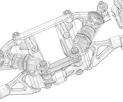
A suspension system rendered with hlr and the visibility of hidden lines enabled.
pattern : specifies the pattern of the hidden lines. (Refer to Set_Line_Pattern for acceptable values. The originally supported numerical values listed in pattern.h are still supported but are deprecated). Note that if you are using patterned lines, you should consider using the “remove duplicate lines” rendering option. In certain cases, namely when one shell per topological face is being used, an HLR rendering will result in lines showing up with inconsistent patterning, due to their being overlapped and out of sync. This option causes duplicate lines to be rendered only once, resulting in a better picture.
weight : specifies the weight of the hidden lines. (Refer to Set_Line_Weight for acceptable values)
color : specifies the color of the hidden lines and markers. Examples include “color = red” and “color = (R=1 G=0 B=0)”.
dim factor : specifies the fraction of the current line color’s R, G, and B channels to use for the color of hidden lines and markers. By default, HOOPS will automatically take a fraction of the RGB values to darken the hidden lines and markers.
face displacement : specifies how many units to push faces into z-space. This can help improve hidden line scene quality if distinct polylines/lines are being used to denote user-defined edges on shell/mesh regions, but are not exactly coincident with the actual shell/mesh edges/vertices. The factor sets a tolerance value which allows lines that might not be fully above the shell/mesh surface to still be rendered. (The display of shell/mesh edges themselves does not pose a problem.) Note: hidden line face displacement is separate from the general face displacement value set via Set_Rendering_Options("face displacement = ddd"). Recall that the latter is used to reduce edge-stitching with the Z-buffer hidden surface removal algorithm.
silhouette cleanup: A silhouette edge is defined as any edge for which one adjacent face points towards and the other away from the camera, and is enabled via the edge visibility settings discussed in the geometry section. Silhouette edges can show unpleasant “fishtail” patterns at points on smooth surfaces where curvature in one orientation is very different from the curvature in another (e.g. the inside of a torus). Silhouette cleanup forces a post-processes to remove most of these patterns at a slight performance cost.
render faces : Causes triangles to be flagged for display during a hidden-line rendering. HLR visibility and dim factor are applied appropriately. Faces are either visible or hidden based on a centroid test. Transformed text characters are drawn as triangles with the “render faces” flag forced on.
rendered face sorting algorithm (or rfsa) : Specifies the sorting algorithm that should be used to sort the geometry which is to be drawn using the ‘render faces’ option discussed above.
render text : This causes HOOPS to text to be flagged for display during a hidden-line rendering regardless of its location in the scene.
image outlines : This causes HOOPS to draw a polyline around the edge of where the image previously resided.
Bringing Objects to the Front
Bring to Front in 2D-Scenes
As mentioned above, the function Set_Priority is the preferred method for specifying drawing order of objects in 2D scenes, which generally have no variance in z-values that can be used by an HSR algorithm to produce a specific result.
Additionally, Bring_To_Front can also be used. It allows you to bring a segment or piece of geometry to the front (Bring_To_Front_By_Key could also be used for geometry or segments). Internally, this function also reorders the current segment’s geometry/subsegment list and only functions if hidden surfaces are off in the current segment.
Again, the use of Set_Priority or Bring_To_Front should be limited to controlling the drawing order of wholly 2D scenes containing 2D objects such as polygons, or groups of lines that perhaps represent layers in a 2D drawing.
Bring to Front in 3D-Scenes
If you wish to bring a 3D object to the front in a 3D scene, and still want that object to be correctly hidden surface removed with respect to itself (you want a sphere to still look like a sphere), then you should use the “depth range” rendering option. This involves specifying a normalized Z-buffer range to compress z-values into a subset of what they otherwise would have been. For example, setting “depth range = (0,0)” will force all geometry in the affected segment to be drawn into the front-most Z-bucket. This particular setting would suffer the drawback that it will cause z-fighting amongst any 3D geometry that shares that setting since we’re not allocating any z range at all. To get such pieces of geometry to resolve reasonably well against each other, “depth range = (0,0.1)” should work reasonably well. However, if all the geometry in the segment (or segment tree) with the depth-range setting is 2D (it’s in the same plane), then setting “depth range = (0,0)” would be fine.
The depth range setting does not take affect if the HSR algorithm is set to “none” or “priority”. Recall that just like any other attribute, this setting will affect the contents of the segment as well as subsegments. Therefore, if you wanted to bring forward a piece of geometry that the user selects, you would move it to a segment with the “depth range” setting, and then move it back to it’s original segment after the user deselects it.
Recall that if you simply want to create temporary, overlayed rubberband geometry (like a zoom box), you should use the “quick moves” heuristic described in the scene interaction section.
Although “face displacement” is typically used to alleviate edge stitching and edge shinethrough, it can also be used to push objects in front of or behind others. One common example is when a mesh is used to represent the location of a cutting plane. Thus, it needs to be pushed ‘in front of’ the cutting plane so it doesn’t get cut away.
Mixing Hidden Surface Removal Algorithms
Only a single hidden surface removal algorithm should be set per HOOPS/3dGS ‘driver instance’. Recall that a driver instance is a subsegment of a HOOPS/3dGS driver segment. For example, in “/driver/opengl/window0”, if subsegments of a driver instance segment contain disparate hsr algorithms, the result correctness of the picture is not guaranteed. Consider the problem that could arise if two algorithms such as Z-buffer and painter’s were mixed: the contents of one segment are rendered using hardware Z-buffer, and placed in the main frame buffer, and then the contents of another segment are rendered using painters and painted wholly ‘on top’ of the contents of frame buffer. The two algorithms don’t ‘know’ about each other (meaning, the painter’s algorithm doesn’t look at the Z-buffer’s contents when determining what lies in front of what). If the objects in the two different segments should be intersecting, the picture would then look incorrect.

