Applying Materials
This tutorial will demonstrate how to apply materials to a shell. A shell is one of the fundamental and most versatile geometric objects of HOOPS Visualize Desktop. Creating a portfolio and applying materials will also be discussed. The code in this tutorial is demonstrated using the framework of the WPF and MFC sandboxes. Those applications are found in the projects wpf_sandbox and mfc_sandbox in the HOOPS Visualize Desktop solution and you are encouraged to follow along. The sandbox applications contain a basic HOOPS Visualize Desktop window as well as four “User Code” buttons which you can use to invoke the example code and interact with the scene.
The cube sample model used in this tutorial can be found in the samples/data directory in your HOOPS Visualize Desktop installation.
2.1 Loading a Shell
HOOPS Visualize Desktop offers a few primitives for 3D geometric representation, however, the vast majority of geometry will be represented by shells. It is recommended that you read this section of the Programming Guide to gain a deep understanding of shells.
This section of the tutorial will use the sandbox to demonstrate how to load a shell cube from a file. Later, we’ll apply materials to each face. In the sandbox, the view hierarchy is already preconfigured and ready to use, so we can begin without any initialization other than creating the model segment.
    HPS::Model model = HPS::Factory::CreateModel(); // creating the Model
    canvas.GetFrontView().AttachModel(model); // attaching model to the view

    HPS::Stream::ImportNotifier notifier = HPS::Stream::ImportNotifier();

    try {
        HPS::Stream::ImportOptionsKit importOptionsKit = HPS::Stream::ImportOptionsKit();
        importOptionsKit.SetSegment(model.GetSegmentKey()); // model from file is imported into our model segment
        notifier =
            HPS::Stream::File::Import(path_to_file, importOptionsKit); // pauses this thread until the file is finished loading
        notifier.Wait(); // pauses this thread until the file is finished loading
    }
    catch (HPS::IOException ioe) {
        // handle exception as you see fit
    }

    canvas.GetFrontView().FitWorld().Update();
HPS.Model model = HPS.Factory.CreateModel(); // creating the Model
canvas.GetFrontView().AttachModel(model); // attaching it to the view

HPS.Stream.ImportNotifier notifier = new HPS.Stream.ImportNotifier();

try
{
	HPS.Stream.ImportOptionsKit importOptionsKit = new HPS.Stream.ImportOptionsKit();
	importOptionsKit.SetSegment(model.GetSegmentKey());  // model from file is imported into our model segment
	notifier = HPS.Stream.File.Import(path_to_file, importOptionsKit);
	notifier.Wait(); // pauses this thread until the file is finished loading
}
catch (HPS.IOException)
{
	// handle exception
}

 canvas.GetFrontView().FitWorld().Update();
note
To load the model in the screenshot, replace path_to_file with <Visualize_Install_Directory>/samples/data/cube.hsf.
If everything went well, at this point the geometry from the file should be loaded into the model segment. Again, the code above should be placed into one of the Execute methods, such as the one in DemoUser1Command. If you were to start the application now, and run the code above by clicking “User Code X”, you would get an image like the following:
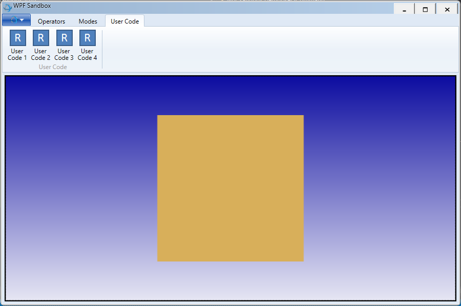
The shell cube
The cube doesn’t look great as it’s unlit and at a flat camera angle. Let’s make the cube look better by adjusting some of the attributes in its segment. We’ll set a transparent color for the faces and enable the visibility of edges:
    HPS::SegmentKey mySegmentKey = canvas.GetFrontView().GetAttachedModel().GetSegmentKey();

    mySegmentKey.GetMaterialMappingControl()
        .SetFaceColor(HPS::RGBAColor(1.0f, 0.0f, 0.0f, 0.5f))
        .SetEdgeColor(HPS::RGBAColor(0, 0, 0));

    mySegmentKey.GetVisibilityControl().SetEdges(true);
HPS.SegmentKey mySegmentKey = canvas.GetFrontView().GetAttachedModel().GetSegmentKey();

mySegmentKey.GetMaterialMappingControl()
    .SetFaceColor(new HPS.RGBAColor(1.0f, 0.0f, 0.0f, 0.5f))
    .SetEdgeColor(new HPS.RGBAColor(0, 0, 0));

mySegmentKey.GetVisibilityControl().SetEdges(true);
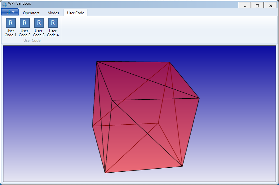
The cube after color and transparency is applied. Note that you can rotate the cube using the orbit operator (first tab in the ribbon control).
Because the materials are set using the segment’s HPS::MaterialMappingControl, the setting will apply to all geometry in that segment - and is also inherited by subsegments. Note that applying materials at the segment level is recommended over setting them at the geometry level because HOOPS Visualize Desktop is able to use performance optimizations when attributes are grouped on segments. However, sometimes it is impossible to arrange the scene in this way because you might, for example, desire to set different materials on faces of the same shell. The following sections will build new materials in a material palette and demonstrate how to apply them to each of the cube’s faces.
2.2 Applying a Diffuse Texture
This section deals with setting a texture on geometry, however, as texture is a material, the procedure in this exercise can be applied to all types of materials. A diffuse texture can be thought of as a standard, unadorned image applied to the face of a geometric object. It is the simplest type of texturing as the face color is simply replaced by the image’s pixels. Details about loading and defining a texture are discussed in depth in the texture section of the Programming Guide. More information on applying materials can be found in this section. The remainder of this tutorial will assume you know how to import images and define materials.
Segment-Level
Like other materials, textures can be applied at the segment, entity, or face level. A segment-level texture means the texture will be applied to every face in the segment - even across disparate geometric bodies (this is the least performance-intensive way to apply materials). An entity-level material will be applied to a single entity, such as a particular shell or mesh. Setting a texture at the face level allows you to control how individual faces are textured - at the expense of rendering speed. For example, the quads below all belong to the same shell. To set a texture to cover all three of them, you could set a segment-level texture by calling:
mySegmentKey.GetMaterialMappingControl().SetFaceTexture("woodDiffuse", HPS::Material::Texture::Channel::DiffuseTexture);
mySegmentKey.GetMaterialMappingControl()
            .SetFaceTexture("woodDiffuse",
            HPS.Material.Texture.Channel.DiffuseTexture);

A shell textured at the segment level
Entity-Level
Materials can be set for individual geometry if the geometry is a shell or mesh. Setting a material on a particular shell or mesh requires using a HPS::MaterialMappingKit. You can set any material property on a HPS::MaterialMappingKit, but for this example, we’ll keep it simple and just set color. To do this, build a kit and apply it to the particular shell key that you want to be different:
    HPS::MaterialMappingKit myMaterialMappingKit;
    myMaterialMappingKit.SetFaceColor(HPS::RGBAColor(0, 0, 1));

    myShellKit.SetMaterialMapping(myMaterialMappingKit);
HPS.MaterialMappingKit myMaterialMappingKit = new HPS.MaterialMappingKit();
myMaterialMappingKit.SetFaceColor(new HPS.RGBAColor(0, 0, 1));

myShellKit.SetMaterialMapping(myMaterialMappingKit);
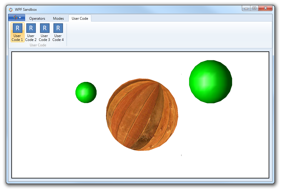
All geometry is in a single segment, and the material is set on just one piece
Setting material at the geometry level does incur a performance penalty relative to setting materials at the segment level.
Face-Level
Face-level texturing is the most performance-intensive way to apply a material. It should be reserved for those times when fine-tuned control of the appearance is absolutely necessary. It also may be appropriate if there are many shells in a segment, but some of the shells have their own specific material. In any case, when applying materials to faces, the primary difference is that the texture itself must be part of a material palette. For this tutorial, we’ll reload the cube model from section 2.1. Six material kits are defined, one for each face of the cube. In each subsection in this tutorial, we’ll build another material to apply to the cube:
    // building the array of six materials
    HPS::MaterialKitArray materialKitArray(6);
    materialKitArray[0].SetDiffuseTexture("woodDiffuse"); // sets a texture on the material

    // ... set other materials

    // defines a palette using the materials
    HPS::MaterialPaletteDefinition mpd = myPortfolio.DefineMaterialPalette("myPalette", materialKitArray);

    // the palette is made active on the segment
    model.GetSegmentKey().SetMaterialPalette("myPalette");
// building the array of six materials
HPS.MaterialKit[] materialKitArray = new HPS.MaterialKit[] { new HPS.MaterialKit(), new HPS.MaterialKit(),
                                                             new HPS.MaterialKit(), new HPS.MaterialKit(),
                                                             new HPS.MaterialKit(), new HPS.MaterialKit() };

materialKitArray[0].SetDiffuseTexture("woodDiffuse"); // sets a texture on the material

// ... set other materials

HPS.MaterialPaletteDefinition mpd = myPortfolio.DefineMaterialPalette
    ("myPalette", materialKitArray); // defines a palette using the materials

// the palette is made active on the segment
model.GetSegmentKey().SetMaterialPalette("myPalette");
The code in the snippet above builds a palette and sets it as the active palette for the segment. The next step sets the mapping between the palette materials and the faces of the shell:
    HPS::SizeTArray faceIndices(6);
    for (size_t i = 0; i < faceIndices.size(); i++)
        faceIndices[i] = i;

    float materialIndices[] = {0, 1, 2, 3, 4, 5};

    myShellKey.SetFaceIndexColorsByList(faceIndices, 0);
ulong[] faceIndices = { 0, 1, 2, 3, 4, 5 };
float[] materialIndices = { 0, 1, 2, 3, 4, 5 };

myShellKey.SetFaceIndexColorsByList(faceIndices, 0);
In this snippet, we are setting the face indices array for all faces, even though we’re only texturing one face at this time (the HPS::MaterialPaletteDefinition has only one real material, as the others are only initialized with defaults). Also note that for this model, the vertex parameters for each face have been stored in the model file. Normally, you will have to set up the vertex parameters as described in this section.
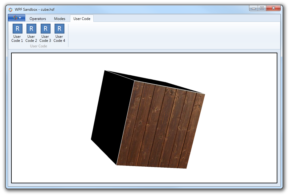
The cube shell with a texture applied to a single face using a material palette.
Lastly, the code in this section assumes you have a reference to the HPS::ShellKey for this shell. When loading from a file, you will not have the keys for the geometry inside. In order to find them, you must search the model segment for the keys. In this case, the procedure is easy as there is only one shell in cube.hsf:
    HPS::SearchResults searchResults;
    size_t numResults = model.GetSegmentKey().Find(HPS::Search::Type::Shell, // searching for shells
                                                   HPS::Search::Space::SegmentOnly, // within the model segment
                                                   searchResults); // search results returned here

    HPS::SearchResultsIterator it = searchResults.GetIterator();
    while (it.IsValid()) {
        HPS::Key key = it.GetItem();

        if (key.Type() == HPS::Type::ShellKey) {
            myShellKey = (HPS::ShellKey)key;
        }

        it.Next();
    }
HPS.SearchResults searchResults;
ulong numResults = model.GetSegmentKey().Find(HPS.Search.Type.Shell,   // searching for circles
                                              HPS.Search.Space.SegmentOnly, // within all subsegments
                                              out searchResults);       // search results returned here

HPS.SearchResultsIterator it = searchResults.GetIterator();
while (it.IsValid())
{
    HPS.Key key = it.GetItem();

    if (key.Type() == HPS.Type.ShellKey)
    {
        myShellKey = new HPS.ShellKey(key);
    }

    it.Next();
}
Applying Diffuse Color Using a Palette
Now that you have an idea of how material palettes work in HOOPS Visualize Desktop, we can revisit simple color. All that is needed is to create a HPS::MaterialKit and set its diffuse color:
materialKitArray[1].SetDiffuse(HPS::RGBAColor(1.0f, 0.0f, 0.0f, 0.5f));
materialKitArray[1].SetDiffuse(new HPS.RGBAColor(1.0f, 0.0f, 0.0f, 0.5f));
Diffuse color and transparency set on one face of the cube.
2.3 Bump Mapping
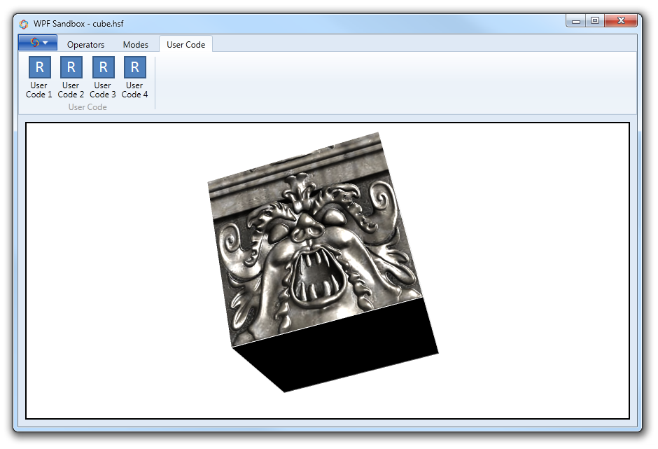
A bump map is a texture that uses a height map in order to create the illusion of a surface with ridges or bumps. Using a bump map is very similar to normal texture mapping. The main difference is the requirement of the height map to provide the height information to the renderer. Since the bump calculation depends on lighting, you must have at least one light in your scene. Bump mapping is most noticeable when the light is able to reflect off of the surface of the geometry (as opposed to being located behind the geometry).
Bump textures have a diffuse component and a height component. Frequently these components are in two separate files - the procedure for loading them as textures in HOOPS Visualize Desktop is identical. Simply load both components as a normal texture. The code below demonstrates how to make two textures into a bump map. In this case we’ll reuse the materialKitArray from the previous section. Note that lighting must be enabled in order to see the bump effect.
    model.GetSegmentKey().InsertDistantLight(HPS::Vector(1, 1, 1));

    materialKitArray[2].SetDiffuseTexture("my_texture");
    materialKitArray[2].SetBump("my_heightmap");
model.GetSegmentKey().InsertDistantLight(new HPS.Vector(1, 1, 1));

materialKitArray[2].SetDiffuseTexture("my_texture");
materialKitArray[2].SetBump("my_heightmap");
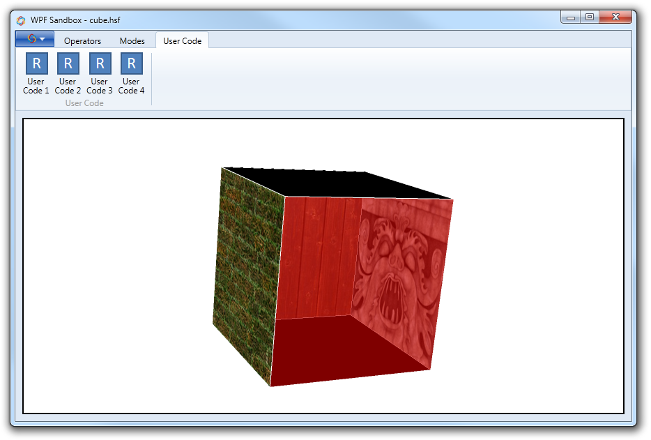
The diffuse texture and heightmap combined to form a finished bump mapped texture.
Note that in order to get the bump texture into the material palette, you must redefine the palette with the new material inside. Normally, you wouldn’t do it this way, as you would simply load all of your textures into the palette at once. But for the purposes of this tutorial, they are loaded separately for clarity’s sake.
2.4 Multi-Texturing
HOOPS Visualize Desktop also supports multitexturing. A multitexture is a texture that is composed of two other textures blended together using modulation. For this example, a brick image and a grass image are loaded. You can have up to eight layers of textures blended together. Only one texture may be modulated, the other must be loaded without modulation.
    textureOptionsKit.SetModulation(true);

    materialKitArray[3].SetDiffuseTexture("brickDiffuse", 0);
    materialKitArray[3].SetDiffuseTexture("grassDiffuse", 1);
textureOptionsKit.SetModulation(true);

materialKitArray[3].SetDiffuseTexture("brickDiffuse", 0);
materialKitArray[3].SetDiffuseTexture("grassDiffuse", 1);
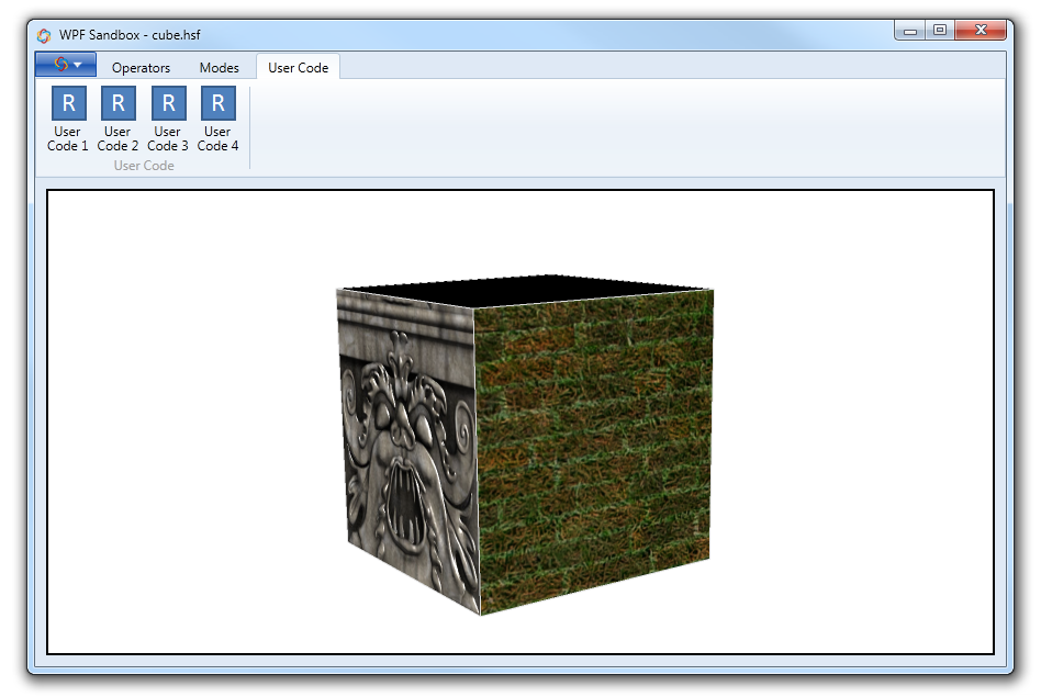
The grass and brick textures blended together using texture modulation.