Material Properties
The perceived color of an object is determined by a complex interaction between the object’s material and the scene’s light sources. Color is made up of a few material properties, such as diffuse, specular, gloss, and transparency. When lights are present in a scene, HOOPS Visualize Desktop the appearance of each pixel as a function of these four properties and the light sources (including the ambient light).
Color Channels
HOOPS Visualize Desktop supports both RGB and RGBA color. Color is a segment-level attribute and, for some geometry, can also be set on subentities (faces, edges, vertices) or interpolated across faces. In HOOPS Visualize Desktop, color is a material component. Thus, to set color for faces or lines at the segment level, you must use the HPS::MaterialMappingControl. The default color for all geometry (including text, lines, polygons, meshes, and shells) is black. Values for each channel must be specified as RGBA color components in the form of floating point values ranging from 0 to 1:
HPS::RGBAColor(1.0f, 0.0f, 0.0f, 1.0f); // red
HPS::RGBAColor(0.0f, 1.0f, 0.0f, 1.0f); // green
HPS::RGBAColor(0.0f, 0.0f, 1.0f, 0.5f); // half-transparent blue
HPS::RGBAColor(1.0f, 0.5f, 0.0f, 0.9f); // mostly opaque orange
Diffuse Color
The diffuse color of an object is the color that the object appears to have when illuminated with a soft, diffuse light. The diffuse color of an object is what we normally think of as the object’s color. The following command sets the diffuse color of the faces in a segment to blue:
    mySegmentKey.GetMaterialMappingControl().SetFaceColor(HPS::RGBAColor(0.0f, 0.0, 1.0f),
                                                          HPS::Material::Color::Channel::DiffuseColor);
mySegmentKey.GetMaterialMappingControl().SetFaceColor
    (new RGBAColor(0.0f, 0.0f, 1.0f), HPS.Material.Color.Channel.DiffuseColor);
Specular Color
Specular color is the opposite of diffuse color - highly specular surfaces are hard and shiny, causing the specular reflected light to have a strong directional component and little scattering. The angle at which light strikes a specular surface is equal to the angle of the reflected ray, which is a view-dependant reflection.
Specular reflectance calculations consider only light that reflects directly from a light source. This reflection approximation does not include any light that would require more than one bounce to reach the camera, nor does it include an actual reflected image of neighboring surfaces as a real-world mirror reflection would. With most nonmetallic objects, the specular reflection color is a shade of white - meaning the specular reflected light maintains the same color (hue) as the light source. For example, the “glare” off a shiny red apple is the color of the light source (white), not the color of the apple (red).
myMaterialKit.SetSpecular(HPS::RGBAColor(1, 0.8f, 0.9f, 0.5f));
myMaterialKit.SetSpecular(new HPS.RGBAColor(1, 0.8f, 0.9f, 0.5f));
Emission
The emission channel is used when you want an object to appear as though light is being emitted from its surface. It is most useful when you have an object you don’t want to appear shaded or shadowed, such as a light bulb. Although emissive light does not brighten other surrounding objects, this effect can be achieved by inserting a light at the point of the emissive object.
There is an overhead cost associated with lighting whenever a scene includes lights. If there are no light sources in your scene, HOOPS Visualize Desktop will skip lighting altogether in order to optimize performance. However, since emission uses lighting calculations (but is not a light source itself), it requires at least one light source to be active in your scene in order to work. If you want emission but don’t require any other lighting, you can insert a black light source.
    mySegmentKey.GetMaterialMappingControl().SetFaceColor(HPS::RGBAColor(1, 0, 0.5f), HPS::Material::Color::Channel::Emission);
    mySegmentKey.InsertDistantLight(Vector(x, y, z)); // IMPORTANT
mySegmentKey.GetMaterialMappingControl().SetFaceColor(new HPS.RGBAColor(1, 0, 0.5f),
                                                      HPS.Material.Color.Channel.Emission);
mySegmentKey.InsertDistantLight(new HPS.Vector(x, y, z)); // IMPORTANT
In summary, almost anything rendered by HOOPS Visualize Desktop can be colored in a custom way. Many objects are composed of subentities that can also be colored. One limitation when coloring geometry is the subentities of geometric primitives such as cylinders and spheres. These objects are dynamically tessellated and contain no subentity information. For example, while you are able to choose a color for all of a sphere’s faces collectively, it is not possible to color an individual face apart from the whole. Note that in general, setting colors on subentities is more computationally intensive for HOOPS Visualize Desktop during the rendering process. For performance reasons, it is best to group similar attributes - including color - into segments, when possible.
For a discussion on applying color at the segment, geometry, or subentity level, see our section on applying materials.
Transparency
There are two components to transparency in HOOPS Visualize Desktop: the method and the algorithm. The method describes what path to take during transparency calculations. Most applications will use a blended method, which is the type of transparency we are all familiar with. Transparent pixels in the foreground are blended with those behind to produce a blended color.
The transparency algorithm specifies the algorithm that calculates the color value when two pixels need to be blended. The default is DepthPeeling, though two Z-sorting algorithms and the painters algorithm is also available.
A simple way to use transparency is build a color object with an alpha value. When not explicitly set, the HPS::RGBAColor object has a default transparency value of 1, or completely opaque. A value of 0 would be completely transparent. To make a partially transparent object, simply set the alpha value to something other than 0 or 1.
    // opaque blue square
    segmentKey1.GetMaterialMappingControl().SetFaceColor(HPS::RGBAColor(0.24f, 0.48f, 0.56f));

    // half-transparent red square
    segmentKey2.GetMaterialMappingControl().SetFaceColor(HPS::RGBAColor(1.0f, 0.0f, 0.0f, 0.5f));
// opaque blue square
segmentKey1.GetMaterialMappingControl().SetFaceColor(new HPS.RGBAColor(0.24f, 0.48f, 0.56f));

// half-transparent red square
segmentKey2.GetMaterialMappingControl().SetFaceColor(new HPS.RGBAColor(1.0f, 0.0f, 0.0f, 0.5f));

Basic transparency
In addition to setting transparency as part of a complete RGBA color, transparency can also be adjusted independently of the color channels. Doing this enables you to set a new alpha value without having to query the system for the current color and build a complete new object. This can be accomplished in this way:
    // adjust front face alpha value
    myMaterialMappingKit.SetFaceAlpha(0.5f);

    // adjust edge alpha
    myMaterialMappingKit.SetEdgeAlpha(0.75f);

    // adjust vertex alpha
    myMaterialMappingKit.SetVertexAlpha(0.25f);
// adjust front face alpha value
myMaterialMappingKit.SetFaceAlpha(0.5f);

// adjust edge alpha
myMaterialMappingKit.SetEdgeAlpha(0.75f);

// adjust vertex alpha
myMaterialMappingKit.SetVertexAlpha(0.25f);
Blending objects with the color of underlying objects is a basic requirement to produce a scene with transparent objects. However, if a transparent object has faces that overlap with one another, or if multiple potentially overlapping transparent objects are present in the scene, they can only be drawn accurately if their faces are sorted with respect to one another. In addition to the basic blending requirement, HOOPS Visualize Desktop will perform extra work to sort the faces of the transparent objects. This results in a more accurate picture, but at the cost of rendering speed. The developer can control both the transparency sorting algorithm and the blending method used to handle the transparent objects by selecting from a number of algorithms, as described in the following subsections.
Transparency Algorithms
Painters Algorithm
The painters algorithm is so named because it works like opaque paint - objects painted later cover up earlier objects. All the objects in a scene are sorted in order of their distance from the viewpoint, with the farthest object first. Then, they are rendered in depth order. As each object is rendered, it covers up any object that is farther away. The painter’s algorithm has a limitation in that it assumes that each object has a single distance from the viewpoint. If an object is not parallel to the screen, then its distance from the screen is actually a range of values. It is possible for several objects to overlap such that there is no ordering that will result in them being rendered properly, as shown in the image below. In this case, it is necessary to split one or more of the objects into smaller pieces.
Three objects that overlap in depth
The painter’s algorithm is a good choice for simple scenes with lots of transparency and non-overlapping geometry. However, its usefulness is limited to those times when hardware acceleration is not available. For complex scenes, it is slow and inferior to all hardware-based sorting algorithms.
Z-Sort
The z-sort algorithm is a faster variation of the painter’s algorithm. It assumes that objects never overlap in depth, so they never have to be split. Z-sort provides a fairly accurate result regardless of how many layers of transparent geometry are in the scene, but will steadily reduce performance as the amount of transparent geometry increases. This is the case because the z-sort algorithm breaks every shell apart into its constituent triangles and then sorts all of those. In HOOPS Visualize Desktop, this type of z-sort is known as HPS::Transparency::Algorithm::ZSortNicest.
A faster but less accurate alternative is to sort based on the center point of each tristrip within a shell. This algorithm is called HPS::Transparency::Algorithm::ZSortFastest, and is useful when high rendering speed is more important than an occasional anomaly in the image. To reduce visual artifacts when using this algorithm, we advise you to enable backplane culling.
Depth Peeling
Depth peeling is an algorithm that “peels away” transparent surface geometry in order to expose any surfaces behind it and therefore calculate a blended color value for the peeled surface. Layers are peeled in passes, thus, a higher number of passes yields a more accurate, but more algorithmically intensive rendering.
Relative to z-sort, depth peeling incurs slightly more overhead when there is only a small amount of transparent geometry, but will run significantly faster when there are large amounts of geometry in the scene. As the number of passes determines the depth to which the transparency is calculated, peeling away only the front most layer has the inherent downside that you will not see any transparent geometry underneath (transparent geometry in deeper layers is ignored). For example, if you wanted to see through two overlapping transparent objects to view opaque object behind them, the second transparent object would not be drawn. In these cases, it would be advisable to set the number of layers to a value appropriate for the scene.
Depth peeling is the default algorithm. It is supported in hardware by most modern GPUs and generally gives the best trade-off between scene quality and performance. Choosing any transparency algorithm is done through the HPS::TransparencyControl.
    // setting the transparency algorithm to "depth peeling"
    mySegmentKey.GetTransparencyControl().SetAlgorithm(HPS::Transparency::Algorithm::DepthPeeling);

    // Visualize will "peel away" three layers when calculating transparency (only meaningful with depth peeling)
    mySegmentKey.GetTransparencyControl().SetDepthPeelingLayers(3);
// setting the transparency algorithm to "depth peeling"
mySegmentKey.GetTransparencyControl().SetAlgorithm(HPS.Transparency.Algorithm.DepthPeeling);

// Visualize will "peel away" three layers when calculating transparency (only meaningful with depth peeling)
mySegmentKey.GetTransparencyControl().SetDepthPeelingLayers(3);
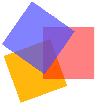
In this image, blue is on top of red, on top of orange, and all objects have transparency. Since depth peeling is set to three layers, all the geometry is visible.
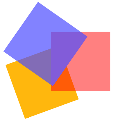
In this slightly different image, depth peeling is set to two layers. As the orange square is partially transparent, it is ignored for color calculations beyond level two, and thus is not visible where the blue and red squares overlap.
Remember, depth peeling only affects transparent objects. If the orange square was opaque, it would be blended with foreground objects - and thus visible behind them - regardless of the depth layer setting.
Transparency Methods
Blended
This method will add values of overlapping pixels, taking into account their alpha values, in order to produce a blended pixel. This is the method used in the screenshot shown above. HPS::Transparency::Method::Blended will give you the most realistic effect, but it generally more intensive that the screen door method, described in the next subsection.
Screen Door
If you have a situation in which you want to forego high visual quality for the sake of performance, HOOPS Visualize Desktop offers the transparency method called screen door. This pseudo-algorithm does no blending, but can be used as a shortcut when rendering speed is very important. When this option is selected, only a fraction of the pixels of the transparent object will be drawn, effectively allowing the user to see through the transparent object. Like real transparency, a larger alpha value will reveal more of the underlying geometry. As the transparency method directly affects the transparency algorithm, screen door does not makes sense when using the blending algorithms such as depth peeling or z-sort, since screen door does no blending.
    // enables the "screen door" method
    windowKey.GetTransparencyControl().SetMethod(HPS::Transparency::Method::ScreenDoor);

    // the default transparency method is "blended"
    windowKey.GetTransparencyControl().SetMethod(HPS::Transparency::Method::Blended);

    // disables transparency
    windowKey.GetTransparencyControl().SetMethod(HPS::Transparency::Method::None);
// enables the "screen door" method
windowKey.GetTransparencyControl().SetMethod(HPS.Transparency.Method.ScreenDoor);

// the default transparency method is "blended"
windowKey.GetTransparencyControl().SetMethod(HPS.Transparency.Method.Blended);

// disables transparency
windowKey.GetTransparencyControl().SetMethod(HPS.Transparency.Method.None);
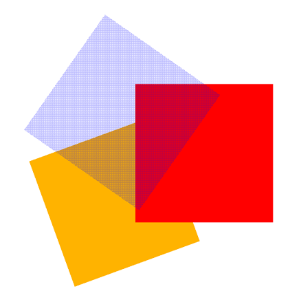
This image demonstrates the screen door method. The red and orange squares have been made opaque to emphasize the effect the method has on the blue square.
Gloss
Gloss is another setting that helps to determine the specular response of a material. It is a single floating point value that describes the “focus” of specular reflections off a surface. A problem with point light sources (distant, local, and spot lights) is that they are infinitely small. The viewed specular “glare” of a point source off a perfect mirror would be correspondingly small (a single pixel). The gloss value changes the area of the “glare” off a surface—a high gloss value gives a small, focused glare; a low gloss value results in a less polished, more scattered reflection. Gloss is an approximation that can be thought of as giving point light sources area, or as a way of partially scattering specular surface reflections. Gloss is always positive, and most surfaces have a gloss in the range from 1.0 to 30.0.
myMaterialKit.SetGloss(15.0f);
myMaterialKit.SetGloss(15.0f);