Fundamentals
This tutorial is intended to describe the fundamentals of how to use HOOPS Visualize Desktop in a simple application. It will demonstrate basic segment operations, creating geometry, loading a model, and setting attributes in the scene graph. For C# users, it is recommended that you follow along in the wpf_sandbox, as an application framework and rendering context are already setup for you. C++ users should use the mfc_sandbox.
The tutorial provides code samples that you can copy and paste into the project source to run in the application. If you are using the WPF sandbox, the example code should be placed in one of the Execute methods of the DemoUser**X**Command classes. These classes are found in DemoUserCommands.cs and are linked to the buttons in the ribbon control of the sandbox:
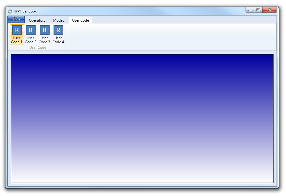
The ribbon control which contains the User Code buttons
If you are using the MFC sandbox, the code samples belong in the CHPSView::OnUserCodeX methods of CHPSView.cpp.
IMPORTANT: All HOOPS Visualize Desktop classes are members of the HPS namespace. You will need to either prepend the namespace to the beginning of each class name, or declare a namespace in your source so that the compiler can find the classes you’re trying to reference. The code snippets provided as examples may not include the namespace identifier for each class.
1.1 Basic Segment Operations
This section reviews basic segment operations in HOOPS Visualize Desktop. If you are new to HOOPS Visualize Desktop or otherwise unfamiliar with the terminology and data structures, you are encouraged to first read section 1.1 as well as section 3.1 of the Programming Guide as a prerequisite to this page.
The sandbox applications both use the view hierarchy for organizing the scene in a window. The Canvas-Layout-View hierarchy is already in place, but you need to create the final piece, the Model. Behind the scenes, the Model is actually a segment, and it can be referenced by a HPS::SegmentKey object, just like any other segment. After creating the Model, it then gets bound to the View in so that the contents of the Model segment are included in the rendering pipeline.
        // create the Model object
        HPS::Model myModel = HPS::Factory::CreateModel();

        // get a reference to the View
        HPS::View myView = GetCanvas().GetAttachedLayout().GetAttachedView();

        // attach the Model to the View
        myView.AttachModel(myModel);

        // you can also get a reference to the Model segment
        HPS::SegmentKey myModelKey = myModel.GetSegmentKey();
// create the Model object
HPS.Model myModel = HPS.Factory.CreateModel();

// get a reference to the View
HPS.View myView = GetCanvas().GetAttachedLayout().GetAttachedView();

// attach the Model to the View
myView.AttachModel(myModel);

// you can also get a reference to the Model segment
HPS.SegmentKey myModelKey = myModel.GetSegmentKey();
In the code example above, the HOOPS Visualize Desktop scene graph that describes your model would be built out from the myModelKey segment. But how is the scene graph actually built? There are two ways that this is done: by creating subsegments and attaching branches.
Creating Subsegments
Creating a new subsegment is always done by calling SegmentKey::Down or SegmentKey::Subsegment. Doing this recursively enables you to make a scene graph of any needed size.
        // get a reference to the Model segment
        HPS::SegmentKey myModelKey = myModel.GetSegmentKey();

        // create children of the model segment
        HPS::SegmentKey childSegment1 = myModelKey.Subsegment();
        HPS::SegmentKey childSegment2 = myModelKey.Subsegment();

        // create a grandchild segment by calling Subsegment on the child
        HPS::SegmentKey grandchild = childSegment1.Subsegment();
// get a reference to the Model segment
HPS.SegmentKey myModelKey = myModel.GetSegmentKey();

// create children of the model segment
HPS.SegmentKey childSegment1 = myModelKey.Subsegment();
HPS.SegmentKey childSegment2 = myModelKey.Subsegment();

// create a grandchild segment by calling Subsegment on the child
HPS.SegmentKey grandchild = childSegment1.Subsegment();
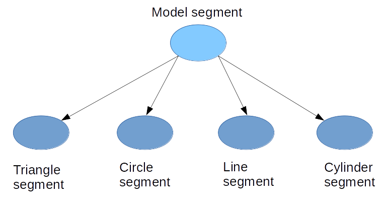
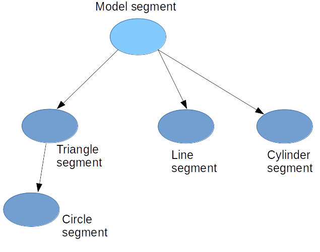
The code above would produce a scene graph of the following form:
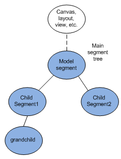
A diagram of this segment hierarchy
When a subsegment is created, it is empty of geometry, but always inherits the attributes of the parent segment. You can override these inherited attributes by setting local attributes on the child segment. Local attributes always override inherited attributes, except in the case of attribute lock.
Attaching Branches
Attaching a branch is the second way you can grow your scene graph. In HOOPS Visualize Desktop, attaching a branch is called including, and the object used to do this is called an include segment. Include segments are useful because a single instance can be attached at multiple locations in the hierarchy. So if you have model subassemblies that are identical, you can keep one copy of the subassembly, saving memory. Updates are also made easier because any changes in one included branch will be reflected in the others. Let’s say you would like to include the root segment in the diagram below under the Model segment:
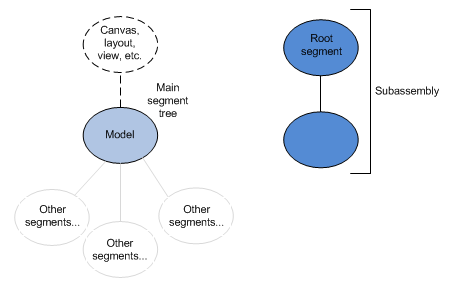
Diagram showing the main segment tree along with a separate root segment structure
The code sample below demonstrates how to do this:
        // get a reference to the Model segment
        HPS::SegmentKey myModelKey = myModel.GetSegmentKey();

        myModelKey.IncludeSegment(subassemblySegment); // first branch
        myModelKey.IncludeSegment(subassemblySegment); // second branch
// get a reference to the Model segment
HPS.SegmentKey myModelKey = myModel.GetSegmentKey();

myModelKey.IncludeSegment(subassemblySegment); // first branch
myModelKey.IncludeSegment(subassemblySegment); // second branch
The resulting scene graph would be arranged as such:
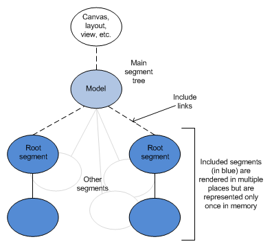
Diagram showing the scene tree with the segments included
Segments can also be moved, copied, and deleted using the following commands:
        // move a segment to a new parent
        someSegment.MoveTo(newParentSegment);

        // copy a segment to another parent
        someSegment.CopyTo(anotherSegment);

        // delete a segment
        childSegment.Delete();
// move a segment to a new parent
someSegment.MoveTo(newParentSegment);

// copy a segment to another parent
someSegment.CopyTo(anotherSegment);

// delete a segment
childSegment.Delete();
Note that in a real application, you would probably want to insert intermediate segments between the Model and the include segments in order to set any attributes that would be specific to those branches, such as position or rotation.
1.2 Creating Geometry
Every piece of geometry has one and only one segment associated with it. Geometry cannot be shared among segments, nor can it exist independently of a segment. The most common types of geometry typically used in a HOOPS Visualize Desktop scene are shells and meshes. HOOPS Visualize Desktop also contains two 3D geometric primitives, spheres and cylinders, as well as 2D lines, curves, and text. In order to eventually build up to the subsection on attributes, we will insert some examples of geometry into the scene graph structure from snippet t.1.1.b.
Shells
Shells are the basic building blocks of most 3D geometry. To create a shell, you need to specify its vertices and face list. For a basic shell, such as a triangle, this is rather simple. The code below will create a triangular shell out of three vertices and a face list.
        Point myPointArray[] = {Point(0, 0, 0), Point(0, 1, 0), Point(1, 1, 0)};
        int myFaceList[] = {3, 0, 1, 2};

        HPS::SegmentKey shellSegment = myModel.GetSegmentKey().Subsegment();
        shellSegment.InsertShell(3, myPointArray, 4, myFaceList);
HPS.Point[] myPointArray = { new HPS.Point(0, 0, 0), new HPS.Point(0, 1, 0), new HPS.Point(1, 1, 0) };
int[] myFaceList = { 3, 0, 1, 2 };

HPS.SegmentKey shellSegment = myModel.GetSegmentKey().Subsegment();
shellSegment.InsertShell(myPointArray, myFaceList);
Shells can be made with any number of vertices or faces by increasing the points and face lists. However, for complex shells with many vertices and faces it is usually easier to build the model in an external modelling program and import it into HOOPS Visualize Desktop at run time.
2D-Geometry
HOOPS Visualize Desktop supports 2D geometry such as lines, curves, and arcs. All lines are polylines, even if they consist of a single segment. Ellipses and circles are the only types of 2D geometry that are considered to be logically closed and facetted. Inserting a circle and a line can be done using the following code (note that line visibility may be off by default - you need to enable it):
        HPS::SegmentKey circleSegment = myModel.GetSegmentKey().Subsegment();
        circleSegment.InsertCircle(Point(2, 0.5f, 0), 0.5f, Vector(0, 0, 1));

        HPS::SegmentKey lineSegment = myModel.GetSegmentKey().Subsegment();
        lineSegment.InsertLine(Point(3, 0.5f, 0), Point(4, 0.5f, 0));
        lineSegment.GetVisibilityControl().SetLines(true);
HPS.SegmentKey circleSegment = myModel.GetSegmentKey().Subsegment();
circleSegment.InsertCircle(new HPS.Point(2, 0.5f, 0), 0.5f, new HPS.Vector(0, 0, 1));

HPS.SegmentKey lineSegment = myModel.GetSegmentKey().Subsegment();
lineSegment.InsertLine(new HPS.Point(3, 0.5f, 0), new HPS.Point(4, 0.5f, 0));
lineSegment.GetVisibilityControl().SetLines(true);
Primitives
3D primitives are inserted in a similar way:
        HPS::SegmentKey cylinderSegment = myModel.GetSegmentKey().Subsegment();
        cylinderSegment.InsertCylinder(Point(5, 0, 0.5f), Point(5.3f, 1, 0), 0.5f);
HPS.SegmentKey cylinderSegment = myModel.GetSegmentKey().Subsegment();
cylinderSegment.InsertCylinder(new HPS.Point(5, 0, 0.5f), new HPS.Point(5.3f, 1, 0), 0.5f);
At this point, the geometry is represented by the following scene graph:
Segment structure
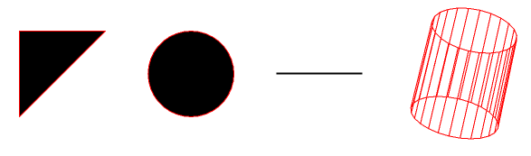
If you compile and run the code snippets from this section, you would end up with something like this:

The example geometry
This geometry is hard to visualize because it is only drawn in silhouette. We’ll add some attributes in the next subsection to improve the appearance.
1.3 Setting Attributes
Attributes are what give geometry its particular appearance. For example, color, edge weight, and visibility are all configurable attributes. All attributes have a default value - the reason the geometry all appears in black in the image above is because black is the segment’s default color. Attributes are inherited from parent to children, and with this in mind, we can begin to assign new attributes to the segments we created earlier.
First, let’s turn off faces on the cylinder to get a better idea of its orientation. We can make this setting in the Model segment or in the cylinder’s segment, and the effect would be the same for the cylinder. However, since attributes inherit, disabling face visibility in the Model segment would also cause faces to disappear in all the child segments as well.
Let’s set the edge color to red in the Model segment and disable face visibility in the cylinder segment:
        myModel.GetSegmentKey().GetMaterialMappingControl().SetEdgeColor(RGBAColor(1, 0, 0));
        cylinderSegment.GetVisibilityControl().SetFaces(false);
myModel.GetSegmentKey().GetMaterialMappingControl().SetEdgeColor(new HPS.RGBAColor(1, 0, 0));
cylinderSegment.GetVisibilityControl().SetFaces(false);
Running the code above, we get the following result:

Setting the edge color and disabling faces
What happened to the cylinder? And why didn’t the edges of the other geometry turn red? The reason is that edge visibility is an attribute that is disabled by default. HOOPS Visualize Desktop assigns a default value to all attributes at the root of the scene graph, and this value was inherited all the way down to the cylinder segment. Let’s fix this by enabling edge visibility in the model segment:
myModel.GetSegmentKey().GetVisibilityControl().SetEdges(true);
myModel.GetSegmentKey().GetVisibilityControl().SetEdges(true);
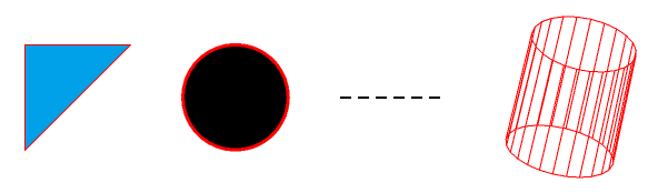
The scene with edge visibility enabled
Much better. We see the triangular shell and the circle have a border. Why didn’t the line change to red? In HOOPS Visualize Desktop, lines and edges are separate types of entities. Lines are used to form line segments and arcs. Edges form the borders of facetted geometry. We only modified the color of the edges, so the line retained its original black color. Now lets add some colors and experiment with the line weights:
        // change face color of shell to blue
        shellSegment.GetMaterialMappingControl().SetFaceColor(HPS::RGBAColor(0, 0.6, 0.9));

        // increase edge weight of circle
        circleSegment.GetEdgeAttributeControl().SetWeight(3.0f);

        // change the solid line to a dashed line
        HPS::PortfolioKey myPortfolio = HPS::Database::CreatePortfolio();

        lineSegment.GetPortfolioControl().Push(myPortfolio);
        HPS::LinePatternKit myLinePatternKitpk = HPS::LinePatternKit::GetDefault(HPS::LinePattern::Default::Dashed);
        myPortfolio.DefineLinePattern("dashed_pattern", myLinePatternKitpk);

        lineSegment.GetLineAttributeControl().SetPattern("dashed_pattern");
// change face color of shell to blue
shellSegment.GetMaterialMappingControl().SetFaceColor(new HPS.RGBAColor(0f, 0.6f, 0.9f));

// increase edge weight of circle
circleSegment.GetEdgeAttributeControl().SetWeight(3.0f);

// change the solid line to a dashed line
HPS.PortfolioKey myPortfolio = HPS.Database.CreatePortfolio();

lineSegment.GetPortfolioControl().Push(myPortfolio);
HPS.LinePatternKit myLinePatternKitpk = HPS.LinePatternKit.GetDefault(HPS.LinePattern.Default.Dashed);
myPortfolio.DefineLinePattern("dashed_pattern", myLinePatternKitpk);

lineSegment.GetLineAttributeControl().SetPattern("dashed_pattern");
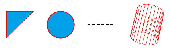
The scene with a few modified attributes
The first two modifications seem easy enough to understand. But why was the process of changing the line pattern so lengthy? The reason for this is that a line pattern is considered to be a defined attribute. This means that you must supply the definition (in this case, a dashed definition) before it can be used in a scene. Along with all other defined attributes, such as textures and glyphs, line patterns exist in a collection called a portfolio. Portfolios must be created and explicitly set on segments before their contents can be used, hence the longer process to get the line pattern to appear.
So far, we’ve been working with each piece of geometry in its own segment. This is fine for demonstration purposes, but in a production application, you will want to organize your segment hierarchy so that segments with common attributes are grouped together. This will ensure performance is at the highest possible level. For example, if you decided you wanted to make the circle blue, you wouldn’t want to set the color in the circle’s segment, as this would create redundant overhead. You can just make the circle segment into a child of the shell segment (or, ideally, just move the circle itself into the shell segment). The color of the shell will inherit to the circle, grouping the attributes into a common branch and keeping performance as high as possible.
circleSegment.MoveTo(shellSegment);
circleSegment.MoveTo(shellSegment);
The circle is a child of the triangular shell, and thus inherits its color
It may not always be feasible to group geometry with common attributes, as sometimes attributes will conflict. But keep in mind that this is the ideal structure and your scene graph should be structured this way when possible.
After the circle segment was moved to become a child of the triangle segment, the scene graph is reorganized in this way:
Scene graph reorganized
1.4 Loading a Model
Section 1.2 dealt with dynamic geometry creation. However, most models loaded into HOOPS Visualize Desktop will be imported from an external file. The HOOPS Visualize Desktop native file format is the HOOPS Stream File, or HSF. An HSF file stores within it all of a model’s attributes and geometric data as well as the scene graph used to organize it. All of the rules about setting attributes and modifying the scene graph described in the previous section still apply to a model loaded from a file.
In HOOPS Visualize Desktop, the call to import a file returns a notifier. A notifier is an object that can be used to query the loading progress of an external file. In general, you should make sure a file is completely loaded before trying to manipulate it.
        HPS::Stream::ImportNotifier notifier;
        HPS::Stream::ImportOptionsKit in_options;
        in_options.SetSegment(GetModel().GetSegmentKey());

        // empty this segment
        GetModel().GetSegmentKey().Flush();

        try {
            notifier = HPS::Stream::File::Import(path_to_file, in_options);
            notifier.Wait();
        }
        catch (HPS::IOException const& e) {
            // handle error
        }

        GetView().FitWorld();
        GetView().Update();
HPS.Stream.ImportNotifier notifier = null;
HPS.Stream.ImportOptionsKit in_options = new HPS.Stream.ImportOptionsKit();
in_options.SetSegment(GetModel().GetSegmentKey());

// empty this segment
GetModel().GetSegmentKey().Flush();

try
{
    notifier = HPS.Stream.File.Import(path_to_file, in_options);
    notifier.Wait();
}
catch (HPS.IOException)
{
    // handle error
}

GetView().FitWorld();
GetView().Update();
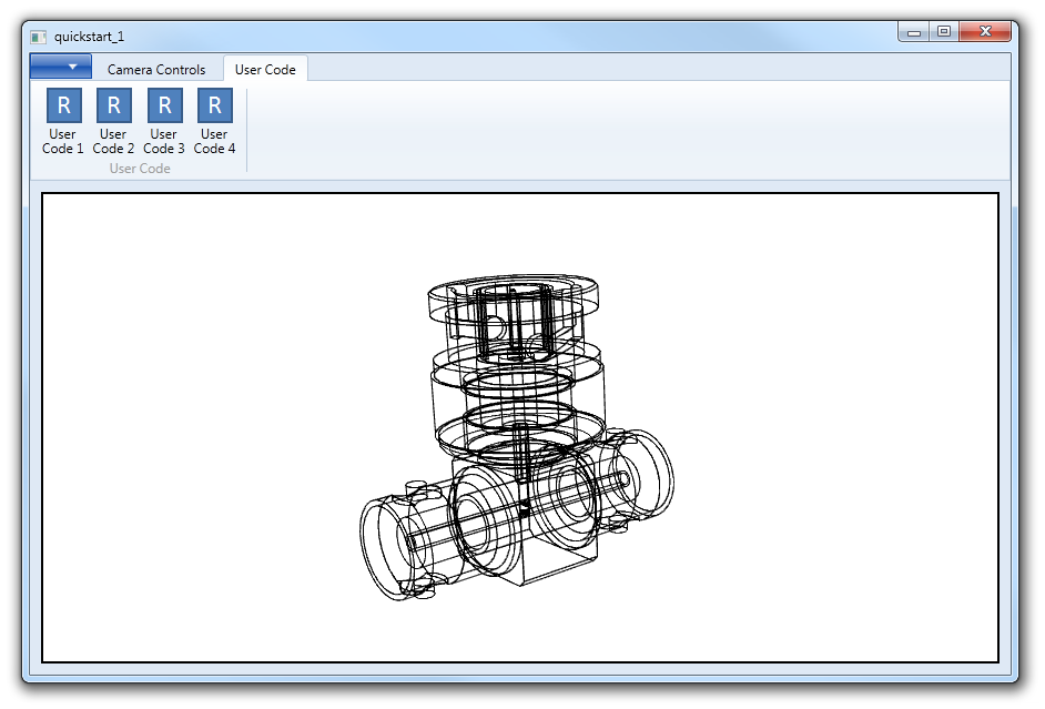
Snippet t.1.4 references bnc.hsf, which can be found in the samples/data directory in your HOOPS Visualize Desktop installation.
In this case, the code will use the notifier to wait for the file to finish loading. Then, it will call FitWorld to zoom the camera to the object extents. Finally, Update is called to draw the scene. If you run this application and click the “User Code 1” button, it should look like this:
A model loaded into the tutorial application
1.5 Visual Effects
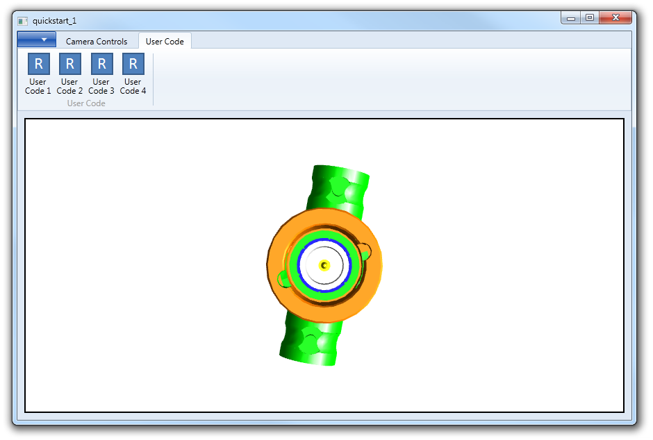
Adding visual effects is a simple operation in HOOPS Visualize Desktop. For example, to show the model using a hidden line mode rendering, use SetRenderMode in the following code snippet. Clicking the “User Code 2” button will toggle the effect.
        HPS::Rendering::Mode render_mode = GetView().GetRenderingMode();

        if (render_mode == HPS::Rendering::Mode::HiddenLine)
            GetView().SetRenderingMode(HPS::Rendering::Mode::Default);
        else
            GetView().SetRenderingMode(HPS::Rendering::Mode::HiddenLine);

        GetView().Update();
HPS.Rendering.Mode render_mode = GetView().GetRenderingMode();

if (render_mode == HPS.Rendering.Mode.HiddenLine)
    GetView().SetRenderingMode(HPS.Rendering.Mode.Default);
else
    GetView().SetRenderingMode(HPS.Rendering.Mode.HiddenLine);

GetView().Update();
The model shown with hidden line mode enabled
Similarly, the part can be shown with a drop-shadow using simple shadows and a shadow plane by clicking “User Code 3”:
        GetView().SetRenderingMode(HPS::Rendering::Mode::GouraudWithLines);

        bool state, ignore_transparency;
        unsigned int resolution, blurring;
        GetView().GetSegmentKey().GetVisualEffectsControl().ShowSimpleShadow(state, resolution, blurring, ignore_transparency);

        HPS::VisualEffectsKit vxfkit;

        if (state == true) // toggle the effect
            vxfkit.SetShadowMaps(false).SetSimpleShadow(false);
        else
            vxfkit.SetShadowMaps(false).SetSimpleShadow(true).SetSimpleShadowPlane(HPS::Plane(0, 1, 0, 0.005f));

        GetView().GetSegmentKey().SetVisualEffects(vxfkit);

        GetView().Update();
GetView().SetRenderingMode(HPS.Rendering.Mode.GouraudWithLines);

bool state, ignore_transparency;
uint resolution, blurring;
GetView().GetSegmentKey().GetVisualEffectsControl().ShowSimpleShadow(out state, out resolution, out blurring, out ignore_transparency);

HPS.VisualEffectsKit vxfkit = new HPS.VisualEffectsKit();

if (state == true) // toggle the effect
    vxfkit.SetShadowMaps(false).SetSimpleShadow(false);
else
    vxfkit.SetShadowMaps(false).SetSimpleShadow(true).SetSimpleShadowPlane(new HPS.Plane(0, 1, 0, 0.005f));

GetView().GetSegmentKey().SetVisualEffects(vxfkit);

GetView().Update();
This code uses the HPS::VisualEffectsKit to enable this effect. Many HOOPS Visualize Desktop attributes are set using their associated kit. For more on attribute controls, see the attribute section of the Programming Guide.
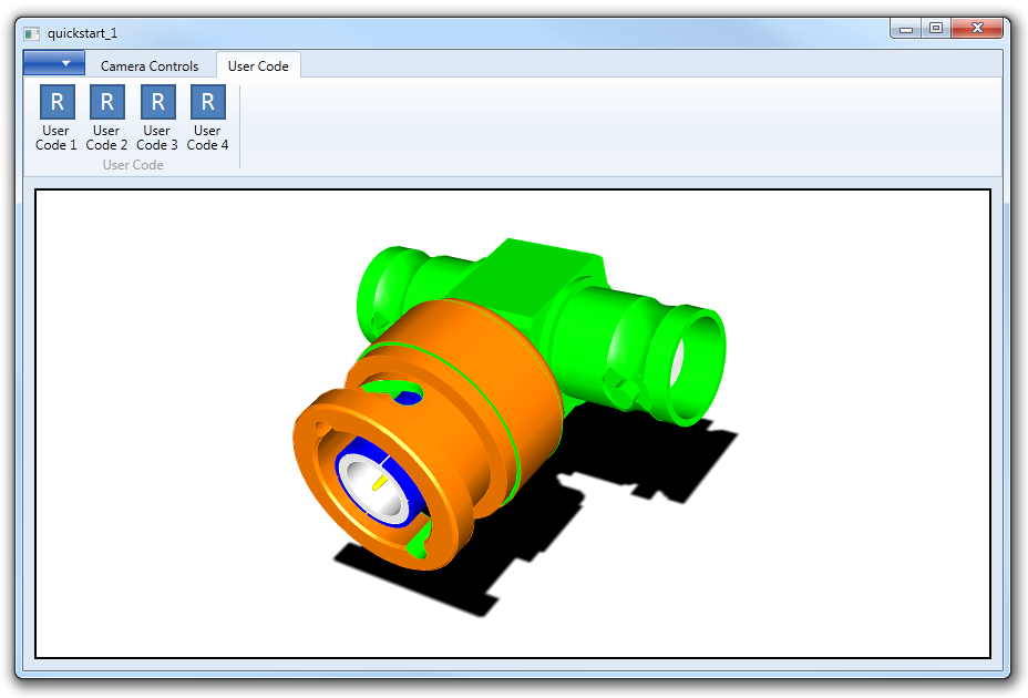
The model shown with a drop shadow
This is the end of the first tutorial. If you’d like to experiment with HOOPS Visualize Desktop, replace the code in any of the “User Code” buttons to execute other commands. Refer to the Programming Guide for more detailed information on the HOOPS Visualize Desktop API.