NURBS
Non-uniform rational b-splines [NURBS] are used to mathematically represent geometry, especially curved surfaces or lines. Because of their flexibility, efficiency, and accuracy, NURBS are the standard way to represent curves in computer modelers. HOOPS Visualize Desktop supports both NURBS curves and surfaces.
NURBS Curves
A NURBS curve is a parametric HOOPS Visualize Desktop primitive, that is, its geometric properties are determined by a set of mathematical functions. For drawing purposes, however, a NURBS curve will inherit from the segment any attributes as if it was a polyline.
A detailed discussion of NURBS curves is beyond the scope of this document. We recommend “The NURBS Book” by Piegl and Tiller as a reference on the topic. That said, NURBS curves can be summarized as having the following properties:
- curve position is determined as a weighted average of its control points.
- the contribution of a given control point is determined by the parameter, “u” (which can vary from 0 to 1), the degree of the curve, the “knot vector”, and the explicit weights that are provided by the user.
- high-degree NURBS curves, like high-degree polynomials, maintain continuity of high-order derivatives.
- the knot vector is simply a nondecreasing array of floats, whose values need not necessarily be unique.
The knot vector has a rather complex way of affecting control point contributions that is best left to a detailed reference on the subject, except to say the following:
- repeated or closely spaced knot values will cause a curve to come near a particular control point.
- repetition of a knot value for a number of times equal to the curve degree will cause the curve to touch a control point. This is often used at the start and end of the curve to make the curve touch its endpoints.
Most of the things that one can do with NURBS curves can also be done with polylines. The only thing that cannot be done by inserting a polyline instead is view-dependent tessellation. By using NURBS curves, users can zoom in to a curve indefinitely without getting noticeable facetting artifacts, provided you are using view-dependant tesselation. If view dependent tessellation is turned off, the curves will be tessellated once based on the other active attributes. If view-dependent tesselation is on, the curves will be re-tessellated whenever the camera moves. The code snippet below demonstrates inserting a basic NURBS curve:
    Point pointArray[] = {Point(-1.75f, -1.75f, 0),
                          Point(-0.75f, -0.75f, 0),
                          Point(-0.5f, 0.5f, 0),
                          Point(0, -0.5f, 0),
                          Point(0.5f, 0.75f, 0),
                          Point(0.75f, 0, 0),
                          Point(2.75f, -1.5, 0)};

    float knotArray[] = {0, 1, 2, 3, 4, 5, 6, 7, 8, 9};
    float weightArray[] = {1, 0.7f, 1, 0.5f, 1, 0.8f, 1};

    HPS::NURBSCurveKit nck;
    nck.SetPoints(7, pointArray);
    nck.SetKnots(10, knotArray);
    nck.SetWeights(7, weightArray);
    nck.SetDegree(2);
    nck.SetParameters(0, 1);

    // enabling view-dependent tesselation
    mySegmentKey.GetCurveAttributeControl().SetViewDependent(true);

    HPS::NURBSCurveKey nurbsKey = mySegmentKey.InsertNURBSCurve(nck);
Point[] pointArray = { new HPS.Point(-1.75f, -1.75f, 0), new HPS.Point(-0.75f, -0.75f, 0), new HPS.Point(-0.5f, 0.5f, 0),
                       new HPS.Point(     0,  -0.5f, 0), new HPS.Point(  0.5f,  0.75f, 0), new HPS.Point( 0.75f,   0, 0),
                       new HPS.Point( 2.75f,  -1.5f, 0) };
float[] knotArray = { 0, 1, 2, 3, 4, 5, 6, 7, 8, 9 };
float[] weightArray = { 1, 0.7f, 1, 0.5f, 1, 0.8f, 1 };

HPS.NURBSCurveKit nck = new HPS.NURBSCurveKit();
nck.SetPoints(pointArray);
nck.SetKnots(knotArray);
nck.SetWeights(weightArray);
nck.SetDegree(2);
nck.SetParameters(0, 1);

// enabling view-dependent tesselation
mySegmentKey.GetCurveAttributeControl().SetViewDependent(true);

HPS.NURBSCurveKey nurbsKey = mySegmentKey.InsertNURBSCurve(nck);
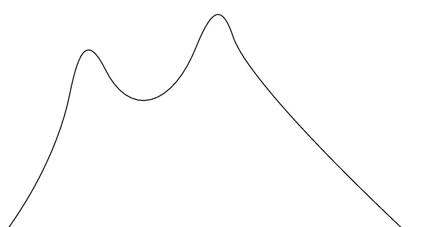
A NURBS curve formed by the above code
Editing Points in a NURBS Curve
Before insertion into the HOOPS Visualize Desktop database, a HPS::NURBSCurveKey will allow you to edit, replace, or delete points, knots, and weights. Editing of existing NURBS curves is limited - there is no way to add or delete components; only modification of existing attributes is supported. The code below is a simple example of how this is done.
    FloatArray newKnots(2);
    newKnots[0] = 3.5f;
    newKnots[1] = 4.5f;
    nurbsKey.EditKnotsByReplacement(3, newKnots);

    PointArray newPoints(2);
    newPoints[0] = Point(-2.5f, -1.5f, -0.5f);
    newPoints[1] = Point(-1.0f, -0.5f, 0.5f);
    nurbsKey.EditPointsByReplacement(0, newPoints);

    FloatArray newWeights(1);
    newWeights[0] = 0.3f;
    nurbsKey.EditWeightsByReplacement(5, newWeights);
float[] newKnots = { 3.5f, 4.5f };
nurbsKey.EditKnotsByReplacement(3, newKnots);

HPS.Point[] newPoints = { new HPS.Point(-2.5f, -1.5f, -0.5f), new HPS.Point(-1.0f, -0.5f, 0.5f) };
nurbsKey.EditPointsByReplacement(0, newPoints);

float[] newWeights = { 0.3f };
nurbsKey.EditWeightsByReplacement(5, newWeights);
Curve Trimming
Two of the arguments needed when defining a NURBS curve are start_u and end_u. These define a simple 1-dimensional form of trimming for NURBS curves. This is particularly useful for importing IGES data, which has such parameters to define the start and end. To make the entire curve visible, values of 0.0 and 1.0 can be passed in for the curve start_u and end_u parameters. Alternatively, to make the first half of the curve visible, use 0.0 and 0.5.
Keep in mind that the curve parameterization always going from 0 to 1 does not match some solid modelers. Instead, solid modeling kernels tend to parameterize with respect to their knot vector. For example, such a modeling kernel would believe that a 3 point quadratic curve with a knot vector {0.2, 0.3, 0.4, 0.5, 0.6, 0.7} would span the range of 0.4 to 0.5. The start_u and end_u would then be expected to be in that range (e.g. [0.41, 0.47]). Use the following formula to convert from the solid modeler parameterization to what HOOPS Visualize Desktop expects:
start_u_hps = (start_u_modeler - knots[degree]) / (knots[control_point_count] - knots[degree]);
end_u_hps = (knots[control_point_count] - end_u_modeler) / (knots[control_point_count] - knots[degree]);
Limitations
HOOPS Visualize Desktop currently does not support a knot multiplicity greater than the order (degree of the curve plus one), which would cause the curve to be completely disjoint at that point. NURBS curves are only defined when knot vectors are non-decreasing, and thus are not supported by HOOPS Visualize Desktop. Weights, however, must not all be zero.
NURBS Surfaces
A NURBS surface is a parametric HOOPS Visualize Desktop primitive - its geometric properties are determined by a set of mathematical functions. For drawing purposes, however, HOOPS Visualize Desktop calculates a polyhedron to represent the NURBS surface. It will be a mesh if untrimmed, and a shell if trimmed. A detailed description of NURBS surfaces is beyond the scope of this document. However, the code sample below demonstrates how to add all of the data needed to for a surface. We recommend “The NURBS Book” by Piegl and Tiller as a reference on the topic.
The following code snippet inserts a NURBS surface:
    static Point const points[] = {Point(3, 1, 0),  Point(1, 1, 0),  Point(0, 2, 0),  Point(-2, 2, 0),  Point(-2, 3, 0),
                                   Point(3, 1, 1),  Point(1, 1, 1),  Point(0, 2, 1),  Point(-2, 2, 1),  Point(-2, 3, 1),
                                   Point(3, -1, 2), Point(1, -1, 2), Point(0, 0, 2),  Point(-2, 0, 2),  Point(-2, 1, 2),
                                   Point(3, -1, 3), Point(1, -1, 3), Point(0, 0, 3),  Point(-2, 0, 3),  Point(-2, 1, 3),
                                   Point(3, 0, 4),  Point(1, 0, 4),  Point(0, -1, 4), Point(-2, -1, 4), Point(-2, 2, 4)};

    PointArray pointArray(points, points + sizeof(points) / sizeof(points[0]));

    float weights[] = {1, 1, 1, 1, 1, 1, 0.5f, 0.5f, 0.5f, 1, 1, 0.5f, 0.5f, 0.5f, 1, 1, 0.5f, 0.5f, 0.5f, 1, 1, 1, 1, 1, 1};

    float uKnots[] = {0, 0, 0, 1, 2, 3, 4, 4, 4};
    float vKnots[] = {0, 0, 0, 1, 2, 3, 4, 4, 4};

    HPS::NURBSSurfaceKit nsk;
    nsk.SetPoints(pointArray);
    nsk.SetWeights(25, weights);
    nsk.SetUKnots(9, uKnots);
    nsk.SetVKnots(9, vKnots);
    nsk.SetUCount(5);
    nsk.SetVCount(5);
    nsk.SetUDegree(3);
    nsk.SetVDegree(3);

    mySegmentKey.InsertNURBSSurface(nsk);
Point[] points = { new HPS.Point(3,  1, 0), new HPS.Point(1,  1, 0), new HPS.Point(0, 2, 0), new HPS.Point(-2,  2, 0), new HPS.Point(-2, 3, 0),
                   new HPS.Point(3,  1, 1), new HPS.Point(1,  1, 1), new HPS.Point(0, 2, 1), new HPS.Point(-2,  2, 1), new HPS.Point(-2, 3, 1),
                   new HPS.Point(3, -1, 2), new HPS.Point(1, -1, 2), new HPS.Point(0, 0, 2), new HPS.Point(-2,  0, 2), new HPS.Point(-2, 1, 2),
                   new HPS.Point(3, -1, 3), new HPS.Point(1, -1, 3), new HPS.Point(0, 0, 3), new HPS.Point(-2,  0, 3), new HPS.Point(-2, 1, 3),
                   new HPS.Point(3,  0, 4), new HPS.Point(1,  0, 4), new HPS.Point(0,-1, 4), new HPS.Point(-2, -1, 4), new HPS.Point(-2, 2, 4) };

float[] weights = { 1, 1, 1, 1, 1, 1, 0.5f, 0.5f, 0.5f, 1, 1, 0.5f, 0.5f,
                    0.5f, 1, 1, 0.5f, 0.5f, 0.5f, 1, 1, 1, 1, 1, 1 };

float[] uKnots = { 0, 0, 0, 1, 2, 3, 4, 4, 4 };
float[] vKnots = { 0, 0, 0, 1, 2, 3, 4, 4, 4 };

HPS.NURBSSurfaceKit nsk = new HPS.NURBSSurfaceKit();
nsk.SetPoints(points);
nsk.SetWeights(weights);
nsk.SetUKnots(uKnots);
nsk.SetVKnots(vKnots);
nsk.SetUCount(5);
nsk.SetVCount(5);
nsk.SetUDegree(3);
nsk.SetVDegree(3);

mySegmentKey.InsertNURBSSurface(nsk);
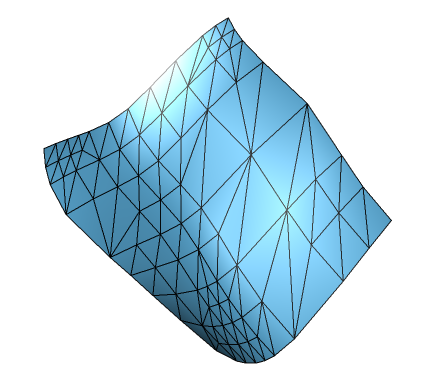
A NURBS surface formed by the above code
Surface Trimming
Associated with a NURBS surface can be any number of trim objects. A trim is a closed geometric loop that delineates a portion of the surface. Each trim element is classified as either a Keep or Remove operation. Trim elements can be vertices and/or control points specified in a two-dimensional u-v parametric space normalized from 0 to 1 over the body of the source NURBS shape.
Trim objects are collections of trim elements and are by default “remove” operations. Trims must be closed loops. If the last point does not meet the first, HOOPS Visualize Desktop will create a line to artificially join them. Portions of the surface that have been trimmed away are never selectable. There are two types of trim objects:
| Trim type | Description |
|---|---|
| Polyline | Each vertex is explicitly specified, as in InsertLine. |
| NURBS curve | The trimming object is itself a NURBS curve. The NURBS curve is tessellated to a resolution specified in the corresponding kit. There is no support for a ``start_u` and end_u parameter for trimming NURBS curves as there is<br>for standard standalone NURBS curves.` |
To visualize NURBS surface trimming, consider the following object:
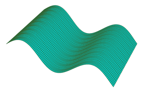
A NURBS surface based on a sine wave
This object can be generated using the code below:
    PointArray pointArray;

    for (float j = 0; j < 10; j++) // width in z direction
    {
        for (float i = 0; i < 10; i += 0.1f) // height and length
        {
            pointArray.push_back(Point(i, sin(i), j));
        }
    }

    HPS::NURBSSurfaceKit nsk;
    nsk.SetPoints(pointArray);
    nsk.SetUCount(10);
    nsk.SetVCount(100);
    nsk.SetUDegree(3);
    nsk.SetVDegree(3);

    mySegmentKey.InsertNURBSSurface(nsk);
HPS.Point[] pointArray = new HPS.Point[1000];
int index = 0;

for (int j = 0; j < 10; j++) // width in z direction
{
    for (float i = 0; i < 10; i += 0.1f) // height and length
    {
        pointArray[index++] = new HPS.Point(i, (float)Math.Sin(i), (float)j);
    }
}

HPS.NURBSSurfaceKit nsk = new HPS.NURBSSurfaceKit();
nsk.SetPoints(pointArray);
nsk.SetUCount(10);
nsk.SetVCount(100);
nsk.SetUDegree(3);
nsk.SetVDegree(3);

mySegmentKey.InsertNURBSSurface(nsk);
Now, let’s say you want to cut a hole, or “trim” in the middle of a NURBS object. This is done using a HPS::TrimKitArray. A trim kit array has several different parts, all arranged hierarchically:
HPS::TrimKitArrayHPS::TrimKitHPS::TrimElementArrayHPS::TrimElementHPS::LineKitorHPS::NURBSCurveKit
For the following example showing surface trimming, we’ll use the NURBS surface from the previous part. Build the object as shown in the previous snippet, however, before inserting it, use the following code.
Step 1: Define the Trim Patterns
In this example, we’ll cut a simple triangle out of the sine-wave curve created above. The first thing we need to do is create the triangular shape:
    PointArray linePoints;

    linePoints.push_back(Point(0.35f, 0.3f, 0));
    linePoints.push_back(Point(0.70f, 0.3f, 0));
    linePoints.push_back(Point(0.5f, 0.7f, 0));
HPS.Point[] linePoints = new HPS.Point[3];

linePoints[0] = new HPS.Point(0.35f, 0.3f, 0);
linePoints[1] = new HPS.Point(0.70f, 0.3f, 0);
linePoints[2] = new HPS.Point(0.5f, 0.7f, 0);
The coordinates used for the line points are all relative to the NURBS surface that you’re trimming. The coordinate system is parametrically scaled from 0 to 1 in both x and y directions. The linePoints array in the code sample above will position a triangle in the center of the surface.
NOTE: The shape must be closed. If you do not close the shape, HOOPS Visualize Desktop will close it for you.
Step 2: Add the Line Points to a TrimElement Object
The HPS::TrimElement expects the trim shape to be encapsulated in a HPS::LineKit or HPS::NURBSCurveKit. In this case we are using only a single HPS::LineKit.
    HPS::LineKit lineKit;

    lineKit.SetPoints(linePoints);
    HPS::TrimElement trimElement;
    trimElement.SetCurve(lineKit);
HPS.LineKit lineKit = new HPS.LineKit();

lineKit.SetPoints(linePoints);
HPS.TrimElement trimElement = new HPS.TrimElement();
trimElement.SetCurve(lineKit);
Step 3: Collect Your Trim Elements into an Array
HOOPS Visualize Desktop allows you to bundle all of your trim objects together in a single operation. If you wanted to cut out multiple pieces of the surface, you would use multiple trim elements. In this case, we are only cutting one piece out of the original NURBS surface. However, the array is still necessary.
    HPS::TrimElementArray trimElementArray;
    trimElementArray.push_back(trimElement);
HPS.TrimElement[] trimElementArray = new HPS.TrimElement[1];
trimElementArray[0] = trimElement;
Step 4: Initialize the TrimKit
The HPS::TrimKit is where you include your array of trim elements. You also need to specify whether this collection of trim elements will be a HPS::Trim::Operation::Keep or HPS::Trim::Operation::Remove operation.
    HPS::TrimKit trimKit;
    trimKit.SetOperation(HPS::Trim::Operation::Remove);
    trimKit.SetShape(trimElementArray);
HPS.TrimKit trimKit = new HPS.TrimKit();
trimKit.SetOperation(HPS.Trim.Operation.Remove);
trimKit.SetShape(trimElementArray);
Step 5: Collect All Trim Kits into an Array
HOOPS Visualize Desktop allows you to apply multiple types of trims in one operation. To do this, you would build multiple trim kits. In this case, we just have one:
    HPS::TrimKitArray trimKitArray;
    trimKitArray.push_back(trimKit);
HPS.TrimKit[] trimKitArray = new HPS.TrimKit[1];
trimKitArray[0] = trimKit;
Step 6: Apply to the NURBSSurfaceKit
The final step is to apply the trim kit array that we’ve built over the last 5 steps to the NURBS surface. At this point, the trim is built and ready to be applied to any NURBS surface kit.
    nurbsSurfaceKit.SetTrims(trimKitArray);

    mySegmentKey.InsertNURBSSurface(nurbsSurfaceKit);
nurbsSurfaceKit.SetTrims(trimKitArray);

mySegmentKey.InsertNURBSSurface(nurbsSurfaceKit);
After the surface is inserted into the segment, the trim can be seen:
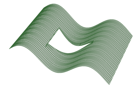
The NURBS surface with a triangular hole trimmed out