Cylinders
In HOOPS Visualize Desktop, cylinders, like spheres, are a type of primitive geometry. They have a smaller memory footprint and can be rendered more quickly than shells. These two features can create many advantages for developers who have models that lend themselves to cylindrical representations.
Cylinders are defined as two circles, known as end caps, connected to one another with edges to form a tube. To create a cylinder in the HOOPS Visualize Desktop database, use HPS::SegmentKey::InsertCylinder. This function accepts two points (indicating the center points of the end caps) a radius, and an enum. The enum is used to specify if either of the end caps will be rendered. The following sample code shows a cylinder with a 0.55 radius inserted into the database with end caps enabled.
    HPS::CylinderKey cylinderKey = mySegmentKey.InsertCylinder(Point(0.5f, 0.5f, 1), // first point
                                                               Point(-0.75f, -0.5f, -1), // second point
                                                               0.55f, // radius
                                                               HPS::Cylinder::Capping::Both); // capping enum
HPS.CylinderKey cylinderKey = mySegmentKey.InsertCylinder(
    new HPS.Point(0.5f, 0.5f, 1),      // first point
    new HPS.Point(-0.75f, -0.5f, -1),  // second point
    0.55f,                         // radius
    HPS.Cylinder.Capping.Both);        // capping enum
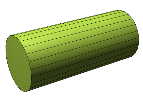
A cylinder inserted using the code above
Cones
Note that if you wish to insert a cylinder with different size radii, you must use a HPS::CylinderKit. One example of this is a cone. In HOOPS Visualize Desktop, a cone is simply a cylinder in which one end is zero radius and the other is non-zero. In the example below, it is inserted using a HPS::CylinderKit. Note that any cylinder that does not have equally sized radii must be inserted using the HPS::CylinderKit.
    Point endPoints[] = {Point(0, 0.5f, 0), Point(0, 0, 0)}; // location of end points
    float radii[] = {0.5, 0}; // the radius of the sphere at each end point

    HPS::CylinderKit cylinderKit;
    cylinderKit.SetPoints(2, endPoints);
    cylinderKit.SetRadii(2, radii);
    cylinderKit.SetCaps(HPS::Cylinder::Capping::Both);

    mySegmentKey.InsertCylinder(cylinderKit);
HPS.Point[] endPoints = { new HPS.Point(0, 0.5f, 0), new HPS.Point(0, 0, 0) }; // location of end points
float[] radii = { 0.5f, 0 }; // the radius of the sphere at each end point

HPS.CylinderKit cylinderKit = new HPS.CylinderKit();
cylinderKit.SetPoints(endPoints);
cylinderKit.SetRadii(radii);
cylinderKit.SetCaps(HPS.Cylinder.Capping.Both);

mySegmentKey.InsertCylinder(cylinderKit);
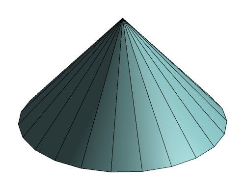
A cylinder rendered as a cone
Notes on Cylinder Subentities
Cylinders, like spheres, are dynamically constructed HOOPS Visualize Desktop primitives. One result of this is that user interaction among subentities is limited. For instance, setting attributes or materials on individual faces, lines, or vertices is not supported nor is altering their position. Cylinder and sphere primitives cannot be textured.
Polycylinders
Polycylinders are a sequence of connected cylinders defined by a collection of vertices and their associated radii. Polycylinders are useful in representing a variety of graphical items. For example, they could be used to depict pipework in a factory or plant, or color-interpolated heat/air/fluid-flow streamlines in CAE post-processing applications.
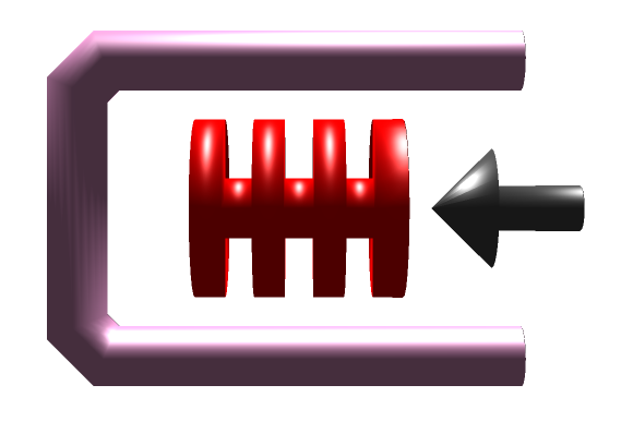
Three different types of models that can be created using polycylinders
In addition to their flexibility as a geometric form, polycylinders have only a slightly larger memory footprint than cylinders and can still be rendered faster than shells. Polycylinder insertion is done similarly to normal cylinders - using HPS::SegmentKey::InsertCylinder. The only difference is that you supply a series of points and radii instead of just the two points for the end caps.
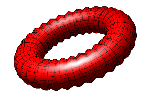
The following code snippet shows how to create a torus using HPS::SegmentKey::InsertCylinder. Here, each point of the polycylinder is computed in a circular pattern. HOOPS Visualize Desktop connects them all to form the object - thus each segment of the torus is logically a single cylinder. Note that one of the last lines of code connects the last point to the first one.
    Point points[65];
    float radius[] = {0.25f};

    for (int i = 0; i < 64; i++) {
        /* Calculating points for the torus*/
        float angle = 2.0f * 3.1415926536f * i / 64.0f;

        float x = 0;
        float y = (float)cos(angle);
        float z = (float)sin(angle) - 1.5f;

        points[i] = Point(x, y, z);
    }

    points[64] = points[0];

    mySegmentKey.InsertCylinder(65, points, 1, radius, HPS::Cylinder::Capping::Both);
HPS.Point[] points = new HPS.Point[65];
float[] radius = { 0.25f };

for (int i = 0; i < 64; i++) {

    /* Calculating points for the torus*/
    float angle = 2.0f * 3.1415926536f * i / 64.0f;

    float x = 0;
    float y = (float) Math.Cos(angle);
    float z = (float) Math.Sin(angle) - 1.5f;

    points[i] = new Point(x, y, z);
}

points[64] = points[0];

mySegmentKey.InsertCylinder(points, radius, HPS.Cylinder.Capping.Both);
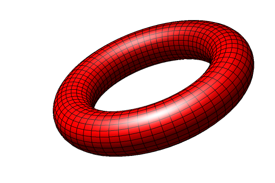
A torus
HOOPS Visualize Desktop will sequentially assign the values from the radius array to each polycylinder point. If there are more points than radii, HOOPS Visualize Desktop will start over with the radius array. Using this technique, interesting effects can be made to the surfaces of the polycylinder. Starting with the code from the previous example, simply change the radius array to include one more element:
    float radii[] = {0.25f, 0.3f};

    // ...

    // don't forget to also specify the new array length to InsertCylinder
    mySegmentKey.InsertCylinder(65, points, 2, radii, HPS::Cylinder::Capping::Both);
float[] radii = { 0.25f, 0.3f };

// ...

// don't forget to also specify the new array length to InsertCylinder
mySegmentKey.InsertCylinder(points, radii, HPS.Cylinder.Capping.Both);
A complex torus created by alternating the radius of each successive point along its path
Tessellation
Tessellation for cylinders is controlled at the segment level using SetTessellation. Using a high tessellation value will result in a smoother rendering at the cost of memory and performance. Tessellating complicated polycylinders can result in a large amount of additional faces, so take care to use the smallest tessellation value that your scene allows.
mySegmentKey.GetCylinderAttributeControl().SetTessellation(40);
mySegmentKey.GetCylinderAttributeControl().SetTessellation(40);
Setting the tessellation to a very low value results in primitive shapes that are not otherwise available in HOOPS Visualize Desktop, such as extruded shapes and pyramids.
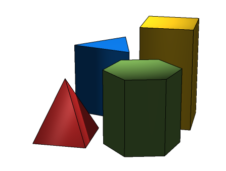
Cylinders with low tessellations
Polycylinder-Polyline Side-Effect
An interesting side effect of polycylinders is that their ability to accept a color at each point can be used to draw polylines of multiple colors, which is not otherwise possible. By setting its radius to 0, a cylinder becomes a line. Setting a color for each point of the cylinder or polycylinder grants you the equivalent of color-interpolated polylines.
    float radius[] = {0};
    Point points[] = {
        Point(-0.5f, -0.5f, 0), Point(0.5f, -0.5f, 0), Point(0.5f, 0.5f, 0), Point(-0.5f, 0.5f, 0), Point(-0.5f, 0, 0)};

    RGBColorArray rgbColorArray(5);
    rgbColorArray[0] = RGBColor(1, 0, 0);
    rgbColorArray[1] = RGBColor(1, 0.5f, 0);
    rgbColorArray[2] = RGBColor(1, 0, 1);
    rgbColorArray[3] = RGBColor(0, 1, 1);
    rgbColorArray[4] = RGBColor(0, 1, 0);

    HPS::CylinderKey ck = mySegmentKey.InsertCylinder(5, points, 1, radius);
    ck.SetVertexRGBColorsByRange(0, rgbColorArray, Cylinder::Component::Faces);
float[] radius = { 0 };
Point[] points = { new HPS.Point(-0.5f, -0.5f, 0), new HPS.Point(0.5f, -0.5f, 0), new HPS.Point(0.5f, 0.5f, 0),
                   new HPS.Point(-0.5f,  0.5f, 0), new HPS.Point(-0.5f,    0, 0) };

RGBColor[] rgbColorArray = new HPS.RGBColor[5];
rgbColorArray[0] = new HPS.RGBColor(1, 0, 0);
rgbColorArray[1] = new HPS.RGBColor(1, 0.5f, 0);
rgbColorArray[2] = new HPS.RGBColor(1, 0, 1);
rgbColorArray[3] = new HPS.RGBColor(0, 1, 1);
rgbColorArray[4] = new HPS.RGBColor(0, 1, 0);

HPS.CylinderKey ck = mySegmentKey.InsertCylinder(points, radius);
ck.SetVertexRGBColorsByRange(0, rgbColorArray, HPS.Cylinder.Component.Faces);
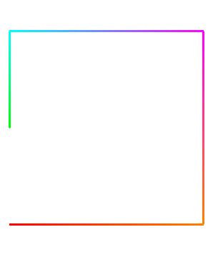
A polycylinder rendered as a line (with increased edge weight for clarity)