Meshes
A mesh is similar to a shell in that it is a collection of faces. But programmatically, a mesh is simpler than a shell, and that simplicity allows it to be stored and displayed more efficiently. A mesh is like a rectangular wirescreen mesh - it can be bent into an arbitrary curved surface, but it is still topologically a quadrilateral.
Examples of Meshes
Geometrically speaking, a mesh is a 2D array of 3D points. However, HOOPS Visualize Desktop expects a 1D array for mesh definition. When speaking of meshes, the terms ‘rows’ and ‘columns’ refer to the rows and columns of points in the mesh, not the faces. For example, a mesh with one square face (two triangles) would have 2 rows and 2 columns. One disadvantage of meshes is that they must be rectangular, that is, each row must have the same number of points as all other rows, and each column must have the same number of points as all other columns.
In the figure below, we see a 3 by 6 mesh (3 rows by 6 columns, for a total of 18 points).
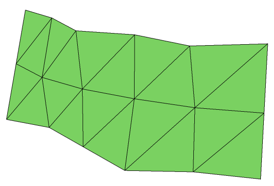
A Simple Mesh
This mesh would be defined as follows:
    PointArray pointArray(18);

    pointArray[0] = Point(-0.8f, 0.4f, -0.8f);
    pointArray[1] = Point(-0.8f, 0, -0.6f);
    pointArray[2] = Point(-0.8f, -0.4f, -0.4f);

    pointArray[3] = Point(-0.4f, 0.4f, -0.4f);
    pointArray[4] = Point(-0.4f, 0, -0.2f);
    pointArray[5] = Point(-0.4f, -0.4f, -0.3f);

    pointArray[6] = Point(0, 0.4f, 0.15f);
    pointArray[7] = Point(0, 0, 0.05f);
    pointArray[8] = Point(0, -0.4f, 0.05f);

    pointArray[9] = Point(0.4f, 0.4f, 0.2f);
    pointArray[10] = Point(0.4f, 0, 0.2f);
    pointArray[11] = Point(0.4f, -0.4f, 0.4f);

    pointArray[12] = Point(0.8f, 0.4f, 0.5f);
    pointArray[13] = Point(0.8f, 0, 0.3f);
    pointArray[14] = Point(0.8f, -0.4f, 0.3f);

    pointArray[15] = Point(1.2f, 0.4f, 0.3f);
    pointArray[16] = Point(1.2f, 0, 0.3f);
    pointArray[17] = Point(1.2f, -0.4f, 0.3f);

    HPS::MeshKey meshKey = mySegmentKey.InsertMesh(6, 3, pointArray);
HPS.Point[] PointArray = new HPS.Point[18];

PointArray[0] = new HPS.Point(-0.8f, 0.4f, -0.8f);
PointArray[1] = new HPS.Point(-0.8f,   0,  -0.6f);
PointArray[2] = new HPS.Point(-0.8f, -0.4f, -0.4f);

PointArray[3] = new HPS.Point(-0.4f, 0.4f, -0.4f);
PointArray[4] = new HPS.Point(-0.4f, 0, -0.2f);
PointArray[5] = new HPS.Point(-0.4f, -0.4f, -0.3f);

PointArray[6] = new HPS.Point(0, 0.4f, 0.15f);
PointArray[7] = new HPS.Point(0, 0, 0.05f);
PointArray[8] = new HPS.Point(0, -0.4f, 0.05f);

PointArray[9] = new HPS.Point(0.4f, 0.4f, 0.2f);
PointArray[10] = new HPS.Point(0.4f, 0, 0.2f);
PointArray[11] = new HPS.Point(0.4f, -0.4f, 0.4f);

PointArray[12] = new HPS.Point(0.8f, 0.4f, 0.5f);
PointArray[13] = new HPS.Point(0.8f, 0, 0.3f);
PointArray[14] = new HPS.Point(0.8f, -0.4f, 0.3f);

PointArray[15] = new HPS.Point(1.2f, 0.4f, 0.3f);
PointArray[16] = new HPS.Point(1.2f, 0, 0.3f);
PointArray[17] = new HPS.Point(1.2f, -0.4f, 0.3f);

MeshKey meshKey = mySegmentKey.InsertMesh(6, 3, PointArray);
…where pointArray is an array of 18 points, specified column by column. Because the way in which the quadrilaterals are connected is fixed, there is no need for a face list as there is in a shell. The points in the mesh are connected into quadrilaterals. The quadrilaterals in a mesh are often not planar (as required by the renderer), so they are further subdivided in half into triangles. The resulting bands of triangles are called triangle strips, or just tri-strips.
It is common for high-end 3D graphics hardware to be optimized to display tri-strips, so using meshes is an especially fast way to display 3D surfaces.
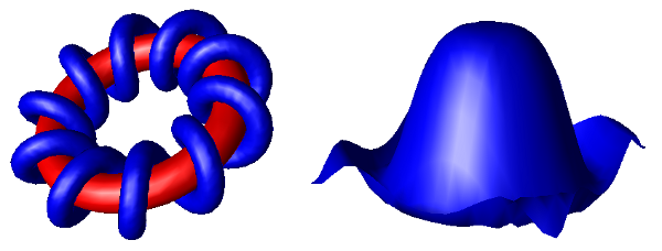
Setting Normals
When using lighting, the vertices of a mesh need to have normals associated with them in order for HOOPS Visualize Desktop to calculate a final color for the mesh. If you do not provide normals, HOOPS Visualize Desktop will approximate them by averaging the normal vectors for each face that shares a particular vertex. However, even for simple shapes such as spheres and cylinders, this average may not appear visually realistic, and can produce lighting anomalies. To avoid this problem, you can set normal vectors explicitly. Normals are typically passed to HOOPS Visualize Desktop in a list and are set all at once on the mesh beginning at a face or vertex index that you specify.
For the purposes of smooth shading, it is best to set normal vectors on the vertices, but you can also set normal vectors on the faces of a mesh, and HOOPS Visualize Desktop will use an average of these normals for smooth shading. You can also unset a normal so that it will revert to its value as calculated by HOOPS Visualize Desktop.
The following code snippet offers an example for setting normals on a mesh:
    // initialize normals
    VectorArray normalArray;
    normalArray.push_back(Vector(1, 0, 0));
    normalArray.push_back(Vector(0.9f, 0.5f, 0.55f));
    normalArray.push_back(Vector(0.8f, 0.4f, 0.4f));

    HPS::MeshKit myMeshKit;

    // for smooth shading, set normals on vertices
    myMeshKit.SetVertexNormalsByRange(0, normalArray);

    // if your model will be flat shaded, set normals on faces
    myMeshKit.SetFaceNormalsByRange(0, normalArray);

    // you may also unset normals in a similar way
    myMeshKit.UnsetFaceNormals();
HPS.Vector[] normalArray = new HPS.Vector[] { new HPS.Vector(1, 0, 0),
                                      new HPS.Vector(0.9f, 0.5f, 0.55f),
                                      new HPS.Vector(0.8f, 0.4f, 0.4f) };

HPS.MeshKit myMeshKit = new HPS.MeshKit();

// for smooth shading, set normals on vertices
myMeshKit.SetVertexNormalsByRange(0, normalArray);

// if your model will be flat shaded, set normals on faces
myMeshKit.SetFaceNormalsByRange(0, normalArray);

// you may also unset normals in a similar way
myMeshKit.UnsetFaceNormals();
NOTE: For convenience, there are many variants of these functions, which are all listed in the HPS::MeshKit reference manual.
Mesh Attributes
The attributes that apply to meshes are almost identical to those that apply to shells. One difference between shells and meshes is that meshes have one additional option for the visibility of edges - it is possible to turn on and off the visibility of the mesh-quad edges separately. The mesh-quad edges are all the edges in the mesh except the edges generated when splitting each quadrilateral face into two triangles. Normally, when edges are visible, all edges are drawn, including the diagonal edges. To turn off the visibility of diagonal edges, first turn off the visibility of edges, and then turn back on the visibility of mesh quads.
    mySegmentKey.GetVisibilityControl().SetEdges(false);
    mySegmentKey.GetVisibilityControl().SetMeshQuadEdges(true);
mySegmentKey.GetVisibilityControl().SetEdges(false);
mySegmentKey.GetVisibilityControl().SetMeshQuadEdges(true);
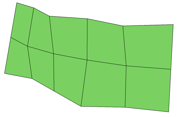
A Mesh Rendered Without Diagonals
It is also possible to set, unset, and show attributes on individual subentities (vertices, edges, and faces) of a mesh. The HPS::MeshKey allows you to make these modifications. For example, to color some faces red, the following code is appropriate:
    SizeTArray faceList(3);
    faceList[0] = 5;
    faceList[1] = 10;
    faceList[2] = 13;

    HPS::RGBColor rgbColor(1, 0, 0);
    meshKey.SetFaceRGBColorsByList(faceList, rgbColor);

    // the same faces could also be made invisible using:
    meshKey.SetFaceVisibilitiesByList(faceList, false);
ulong[] faceList = new ulong[3];
faceList[0] = 5;
faceList[1] = 10;
faceList[2] = 13;

HPS.RGBColor rgbColor = new HPS.RGBColor(1, 0, 0);
meshKey.SetFaceRGBColorsByList(faceList, rgbColor);

// the same faces could also be made invisible using:
meshKey.SetFaceVisibilitiesByList(faceList, false);
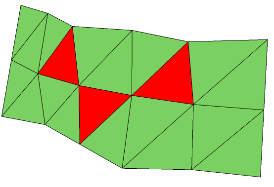
A mesh with only a few faces colored
It is also possible to set multiple colors on multiple faces if the above example is modified to use an RGBColorArray instead of the single color represented by HPS::RGBColor. Like shells, meshes can also be textured as a whole or in part. When texturing or coloring just a few faces of a mesh (rather than the whole mesh), it is necessary to use a Defining Material Palettes. Vertices are numbered as they are arranged in the point list.
How to Locate an Arbitrary Face in a Mesh
Because a mesh has no face list, we need a scheme to number the faces. This is important when setting materials on mesh faces. For meshes defined in row-major order, if we assume:
r = vertex position in a row
c = vertex position in a column
the triangle between (r, c), (r + 1, c), and (r, c + 1) is numbered:
2 * (r * (columns - 1) + c)
Alternatively, the triangle between (r + 1, c + 1), (r, c + 1), and (r + 1, c) is numbered:
2 * (r * (columns - 1) + c) + 1
Note that we begin counting at 0. So the first row would start r = 0 in the calculation.