
Coordinate Systems
Authoring and rendering a scene can be a detailed and dynamic process. Building a scene often requires the creation and manipulation of data at multiple phases. We might create geometry at one point and then apply a modeling matrix to rotate or translate objects in the scene. Then, we could add lights as well as apply a variety of visual effects. Finally, we can define a camera that determines how the scene will be viewed. Once the scene is rendered to a display, we might find that we want a different result so we alter a series of attributes.
The actions described above are part of creating a scene. It is an iterative process that can involve tweaking any number of variables. To accurately change the elements in a scene so that you can get the result that you want, it is important to understand the coordinate systems associated with the different stages of the graphics pipeline.
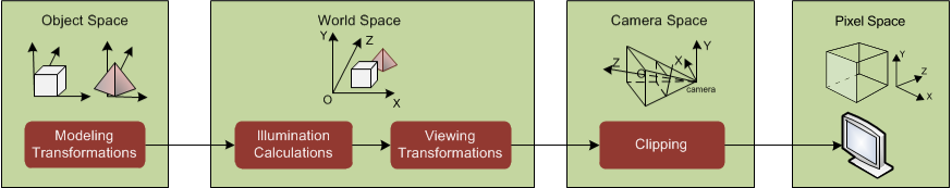
Stages of the graphics pipeline with associated coordinate systems
In the figure above, we see that there are four different coordinate systems:
- Object space: an infinite 3D Cartesian coordinate system local to the object itself.
- World space: an infinite 3D Cartesian coordinate system where objects reside after their modelling transformations have been applied.
- Camera space: a space defined by a camera’s view of world space.
- Pixel space: a coordinate system that represents the ultimate space that your scene is rendered to - sometimes referred to as screen space
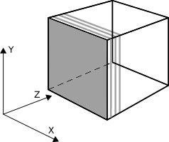
Object Space
When geometry is inserted into the graphics database, it initially inhabits an infinite 3D Cartesian coordination system called object space. Each segment has its own local object coordinate system. Objects are then transformed from object space into world space using the local modelling matrix contained in the segment concatenated with any transforms from the parent segment.
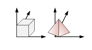
Object space
World Space
HOOPS Visualize Desktop makes no distinction between 2D and 3D space - all geometry exists in the 3D space called world space, which is an infinite 3D Cartesian coordinate system. An object’s position in world space is determined after modelling transformations are performed. In other words, an object’s location in world space is calculated by concatenating all modelling matrices from an object’s parent segment with the transformation information in its own segment and then applying it to the object.
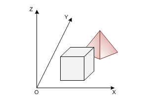
World space
World space is affected by world handedness. The world handedness determines which way the positive z direction points. In HOOPS Visualize Desktop, the default handedness is “right”. The most common effect of setting it backwards is camera movement is opposite of what you’d expect. To set the world handedness to “left”, see the code snippet below:
mySegmentKey.GetDrawingAttributeControl().SetWorldHandedness(HPS::Drawing::Handedness::Left);
mySegmentKey.GetDrawingAttributeControl().SetWorldHandedness(HPS.Drawing.Handedness.Left);
Camera Space
This is the space viewed by cameras in the scene. A camera defines a particular view of world space. The camera space is calculated based on a set of attributes: position, target, field and type. In HOOPS Visualize Desktop, you can set these values via SegmentKey::SetCamera passing the HPS::CameraKit. The vector derived from position and target values give us the Z-direction while the field helps define the extents of the observable world.
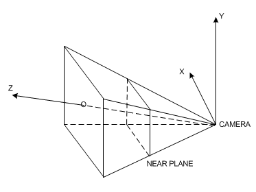
Camera space
Once the camera attributes are taken into account, we can use this information to build a view frustum and calculate what part of the world space can be observed by the camera. Clipping is performed here in the camera space.

Camera and world space
For a more detailed discussion about setting camera attributes and performing clipping, please see our page on cameras.
Pixel Space
After an object has been transformed based on the viewing transform defined by a camera and then clipped, it is projected onto a 2D coordinate system called pixel space. This is also the coordinate system in which GUI events are typically returned. The dimensions of screen space are the same as the number of pixels in the window. Each unit corresponds to a pixel on the screen.
Pixel space
Although screen space is 2D, each pixel does remember the closest object to the camera. Thus, it retains a depth buffer value of the object’s position along the z-axis.
Computing Coordinates Across Coordinate Systems
As HOOPS Visualize Desktop uses a number of different coordinate systems to compose a scene, you may find it necessary to translate coordinates from one coordinate system to another. The translation is handled by the WindowKey and computes each point individually.
    Point windowPoint(-1, -1, 0);
    Point worldPoint;

    windowKey.ConvertCoordinate(HPS::Coordinate::Space::Window, windowPoint, HPS::Coordinate::Space::World, worldPoint);
HPS.Point windowPoint = new HPS.Point(-1, -1, 0);
HPS.Point worldPoint;

windowKey.ConvertCoordinate(HPS.Coordinate.Space.Window, windowPoint, HPS.Coordinate.Space.World, out worldPoint);
The example above converts the point in window space at [-1, -1, 0] to a corresponding point in world coordinates (worldPoint is returned as the result). There are a number of coordinate systems available for translation:
Computing Coordinates During Selection Events
A common computation that needs to be performed during a projected ray selection is to generate the world coordinates of an eye-ray. Given window or pixel coordinates, you would call ConvertCoordinate twice with two different window or pixel z coordinates. For an example of how to do this, see the code snippets in the selection section.
Using Matrices
Each HOOPS Visualize Desktop segment contains a 4x4 matrix which affects the segment geometry’s position, scale, and rotation. A modelling matrix is an attribute, with a default value being the identity matrix. A thorough explanation of how matrices work are beyond the scope of this document, but this section will discuss how matrices affect the HOOPS Visualize Desktop scene graph.
Matrices behave a bit differently than other attributes in that a segment’s modelling matrix is concatenated (multiplied) with its parent segment’s matrix. This lends itself to manipulating a 3D hierarchy, which might involve animation or complex transforms. Since the level of a segment in the tree defines the order in which a matrix will be applied in the list of matrices, it is important to set the desired transform at the correct location. Since modelling matrices behave like other segment attributes, all objects in a segment will be affected by the local modelling transform. Therefore, if you need to transform specific objects within a segment you will need to move those objects into another segment to apply the transform.
Like other settings, matrices in HOOPS Visualize Desktop have an associated kit, the HPS::MatrixKit. When specifying rotation parameters to the matrix controls, these values are specified in degrees.
    // set the segment's matrix
    mySegmentKey.SetModellingMatrix(matrixKit);

    // multiply the segment's matrix with another matrix
    mySegmentKey.GetModellingMatrixControl().Concatenate(matrixKit);

    // get the segment's matrix into a kit
    mySegmentKey.ShowModellingMatrix(matrixKit);

    // perform a rotation (in degrees) on the segment's current matrix
    mySegmentKey.GetModellingMatrixControl().Rotate(10, 50, 90);

    // an individual element in a matrix can also be set as follows:
    mySegmentKey.GetModellingMatrixControl().SetElement(1, 3, -5);

    // unsetting the matrix
    mySegmentKey.UnsetModellingMatrix();
// set the segment's matrix
mySegmentKey.SetModellingMatrix(matrixKit);

// multiply the segment's matrix with another matrix
mySegmentKey.GetModellingMatrixControl().Concatenate(matrixKit);

// get the segment's matrix into a kit
mySegmentKey.ShowModellingMatrix(out matrixKit);

// perform a rotation (in degrees) on the segment's current matrix
mySegmentKey.GetModellingMatrixControl().Rotate(10, 50, 90);

// an individual element in a matrix can also be set as follows:
mySegmentKey.GetModellingMatrixControl().SetElement(1, 3, -5);

// unsetting the matrix
mySegmentKey.UnsetModellingMatrix();
The details for these functions can be found in the ModellingMatrixControl part of the reference manual. The solar system is a good hierarchy to use for demonstrating how matrices accumulate to form an accurate rotation. The segment hierarchy for the solar system might look like the one below:
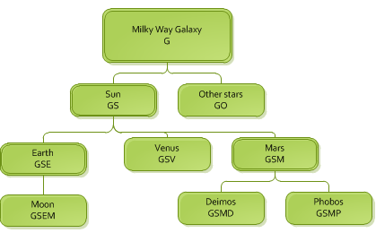
The solar system modeled as a scene graph
The letters under each name indicate a matrix. For example, the Milky Way galaxy contributes its matrix, G, to the Sun. The Sun then multiplies it by its own matrix, S, to get the matrix GS. Following down the tree, we can end up at Phobos, a moon of Mars, with the matrix GSMP. If all bodies in space could be said to have a matrix which locates them in space, you could say that Phobos is located in the universe by combining the matrices of the galaxy, the Sun, Mars, and its own matrix.
These matrices could be rotation or translation matrices - or a combination of both. For example, the Earth matrix E is likely a combination of the rotation, or tilt, on its axis, a translation from the Sun representing its orbital distance, and another rotation which indicates its progress along its yearly orbit. Applied to HOOPS Visualize Desktop, the point is that matrices accumulate down the tree and your segment structure should be organized in a way that makes sense in 3D space.
Note that unsetting a matrix is not a trivial task. If you need a completely different matrix that is not relative to the parent segment’s matrix, you should consider moving the segment to a place in the hierarchy that has a related matrix. Unsetting a matrix on a local segment does not erase the effects of the matrices inherited from above. If that were your goal, you would have to show the net modelling matrix along a draw path (from the segment to a window), then invert the result and apply it to the local segment. Note that there may be multiple paths to a window from your segment, so this is not feasible in the general case.
Remember, the order of these transforms is important, as matrix manipulation is generally not commutative.