
Textures
Texture mapping is the method of applying a 2D image to a 3D geometric surface in order to simulate detail that would not be feasible using geometry alone. Unlike other HOOPS Visualize Desktop settings, textures can be set in two different ways - at the segment level or directly on the geometry. Segment-level texturing will apply the texture to all faces in the segment and subsegments. However, material palettes give you much more control over how the texture is applied, and are the recommended way to apply textures when a segment-level setting is too broad.
A material that is made from a texture makes use of at least one channel. Each channel contains information about the texture which affect the way the texture appears. A normal, unadorned texture uses the diffuse channel.
| Channel name | Description |
|---|---|
| Diffuse | The diffuse channel represents the primary color of a surface. For an untextured surface, the diffuse channel might be a solid color. When texturing a surface, the texture image replaces the colors of the diffuse channel. This is the default setting when applying textures in HOOPS Visualize Desktop. |
| Specular | Texture is applied to the surface of the object as if the texture was a specular highlight |
| Emission | Texture is rendered with colors that appear to glow |
| Transmission | Using the transmission channel, the texture is converted to grayscale, and its values are used to determine opacity. White values are fully transparent, blacks are fully opaque. |
| Mirror | A texture channel to be used as the mirror color. The average intensity of the three chanels determines the relative contribution of the environment over the underlying texture. |
| Bump | The bump channel is used by HOOPS Visualize Desktop to create a surface that appears rough or ridged in order to simulate a higher degree of realism. Bump mapping is described here. |
| EnvironmentTexture | This channel describes a single texture applied to a surface, which appears as a reflection of the surrounding environment. |
| EnvironmentCubeMap | This channel describes six textures applied to a surface, which appears to be a reflection of the environment. Not as susceptible to distortion as EnvironmentTexture. |
NOTE: Most GPUs require texture dimensions to be a power of two. If your texture dimensions are not a power of two, HOOPS Visualize Desktop will automatically downscale the texture to the nearest power of two. One exception is with very small textures. The smallest texture size is 16x16, therefore, if your texture is smaller than this, it will be upscaled to 16x16.
Texturing a polygon or surface is accomplished in a number of steps:
Step 1: Acquire the Image
The most convenient way to import images into HOOPS Visualize Desktop is to using the HPS::Image::File::Import function, although it is possible to use a programmatically-defined or a generated image as texture data. Any byte array will work. Images files are loaded synchronously by HOOPS Visualize Desktop, so if you expect image loading to take a long time, you should use a separate worker thread. The only requirements to specify when loading images are the filename and the image format. Supported 2D image formats are noted here. Any problems associated with loading an image will be reported using an HPS::Image::IOException. In this example, an image of a tree is used to texture a quad.
        ImageKit imageKit;

        try {
            HPS::Image::ImportOptionsKit iok;
            iok.SetFormat(HPS::Image::Format::Png);
            imageKit = HPS::Image::File::Import(filename, iok);
        }
        catch (HPS::IOException ioe) {
            char const* problem = ioe.what(); // shows cause of the exception
        }
                HPS.ImageKit imageKit;

                try
                {
                    HPS.Image.ImportOptionsKit iok = new HPS.Image.ImportOptionsKit();
                    iok.SetFormat(HPS.Image.Format.Png);
                    imageKit = HPS.Image.File.Import(filename, iok);
                }
                catch (HPS.IOException ioe)
                {
                    String problem = ioe.what(); // shows cause of the exception
                    return Test.Result.Failure;
                }
HPS::Image::File::Import returns an HPS::ImageKit. When defining an image in this way, only the image format and filename must be provided. However, when defining images that are loaded without the use of HPS::Image::File::Import, the dimensions, the image format, and the image data itself must be supplied so that the kit can be composed. That operation is described below:
    HPS::ImageKit imageKit;

    // Visualize must know the size of the data and the data itself
    imageKit.SetData(file_size * bytes_per_pixel, imageData);

    // the dimensions of the image
    imageKit.SetSize(256, 256);

    // the format tells Visualize how to interpret the raw data
    imageKit.SetFormat(HPS::Image::Format::RGB);
                HPS.ImageKit imageKit = new HPS.ImageKit();

                // set the data into the ImageKit
                imageKit.SetData(imageData);

                // the dimensions of the image
                imageKit.SetSize(256, 256);

                // the format tells Visualize how to interpret the raw data
                imageKit.SetFormat(HPS.Image.Format.RGB);
Step 2: Define the Image in a Portfolio
A portfolio is a collection of data that is accessible to your application. Portfolios are discussed in the Portfolios section. The topic explained here is no exception - the image imported in the previous step must be defined in a portfolio. Data in a portfolio is accessible to any segment that uses the portfolio (this includes segments that inherit the portfolio from an ancestor). Best practices suggest the image itself should be given a name.
    HPS::PortfolioKey portfolioKey = HPS::Database::CreatePortfolio();

    // import image to portfolio
    HPS::ImageDefinition imageDefinition = portfolioKey.DefineImage("my_image", imageKit);
                HPS.PortfolioKey portfolioKey = HPS.Database.CreatePortfolio();

                // import image to portfolio
                HPS.ImageDefinition imageDefinition = portfolioKey.DefineImage("my_image", imageKit);
Step 3: Define a Texture From the Image
Defining the image as a texture makes it available as a texture map. The texture must be given a name so that it can be referenced later when it gets applied.
note
Note that the image needs to be defined in the same portfolio as the texture.
    HPS::TextureOptionsKit textureOptionsKit;

    // see the table below about parameterization sources
    textureOptionsKit.SetParameterizationSource(HPS::Material::Texture::Parameterization::UV);

    // makes the image into a texture
    portfolioKey.DefineTexture("my_texture", imageDefinition, textureOptionsKit);
                HPS.TextureOptionsKit textureOptionsKit = new HPS.TextureOptionsKit();

                // see the table below about parameterization sources
                textureOptionsKit.SetParameterizationSource(HPS.Material.Texture.Parameterization.UV);

                // makes the image into a texture
                portfolioKey.DefineTexture("my_texture", imageDefinition, textureOptionsKit);
As a 2D array of pixels, textures can be mapped to a 3D object in many potential ways. The parameterization source defines this mapping. HOOPS Visualize Desktop offers nine types of parameterization that can be used for geometry:
| Parameterization source | Description |
|---|---|
Cylinder |
Automatically creates the texture map based on a cylindrical mapping. The HOOPS Visualize Desktop Cylinder primitive cannot be textured, although a cylinder or cylinder-like object formed from a shell would benefit from this mapping. |
NaturalUV |
Stretches the texture along meshes and NURBS surfaces according to their natural internal parameterization. For meshes this is range [0..1]. For NURBS surfaces this is range [0..(control point count - degree)]. Shells do not have a natural parameterization, so the [u,v] coordinates are generated according to the following formula: [u=x+z, v=x+y], where x, y, and z are object space coordinates. |
Object |
The XYZ coordinates of the local geometry. Identical to world space (see below) except that this coordinate system is before modelling matrices are applied. |
PhysicalReflection |
An alternative setting for environment mapping. When set, this calculates the environment coordinates as a reflection between the normal (to the item being textured) and the view vector. The result is that the environment map is not held at a fixed position. |
ReflectionVector |
This is the recommended setting for an environment map. It matches the behavior of OpenGL environment mapping, in that the environment is held at a fixed position along the view vector. |
SurfaceNormal |
The surface normal computed for the local screen pixel. |
Sphere |
Automatically creates the texture map based on a spherical mapping. The HOOPS Visualize Desktop Sphere primitive cannot be textured, although a sphere or sphere-like object formed from a shell would benefit from this mapping. |
UV |
Used for traditional image based texture maps. The parameterization source comes from a user supplied (u,v) coordinate set with the SetVertexParameters routine. This is the default value. |
World |
A three-valued parameter (XYZ) corresponding to the surface pixel’s 3D world coordinate position (the coordinate system of geometry after modelling matrices have been applied, but before projecting through a camera into a window). The Z value is ignored unless there is a texture matrix that has set. |
Step 4: Assign the Portfolio to the Segment
The segment must be told to use the portfolio that defines the texture. Note that a segment can only use one portfolio at a time. Portfolios inherit to subsegments just like other attributes.
mySegmentKey.GetPortfolioControl().Push(portfolioKey);
mySegmentKey.GetPortfolioControl().Push(portfolioKey);
Step 5: Set the Vertex Parameters
This step is important because it determines how the image is applied to the geometry. A mapping must be created between a pixel in the image and the vertices of the geometry that will be textured. SetVertexParameters assigns a pixel of the image to a vertex and interpolates the image between them. To this end, any texture using UV parameterization is understood to have [u, v] coordinates that correspond to the corners of the image, as shown below:
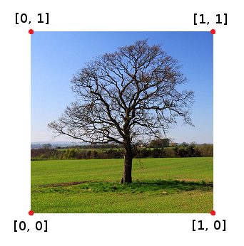
The vertex coordinates
Normally, you would assign each corner of the image to a vertex on the geometry, although that does not necessarily have to be the case. It is possible to use a floating point value between 0 and 1 as a vertex coordinate and HOOPS Visualize Desktop will choose the appropriate texel for each pixel.
    // the vertices_map array corresponds to the vertex indices of the shell
    HPS::SizeTArray vertices_map;
    vertices_map.resize(4);
    vertices_map[0] = 0;
    vertices_map[1] = 1;
    vertices_map[2] = 2;
    vertices_map[3] = 3;

    HPS::FloatArray vparams;
    vparams.resize(8); // for UV coordinates on a quad, see texture coordinates discussion
    vparams[0] = 0;
    vparams[1] = 0; // [0, 0]
    vparams[2] = 1;
    vparams[3] = 0; // [1, 0]
    vparams[4] = 1;
    vparams[5] = 1; // [1, 1]
    vparams[6] = 0;
    vparams[7] = 1; // [0, 1]

    HPS::ShellKit shellKit;
    shellKit.SetPoints(pointArray);
    shellKit.SetFacelist(faceList);
    shellKit.SetVertexParametersByList(vertices_map, vparams, 2);
                // the vertices_map array corresponds to the vertex indices of the shell
                ulong[] vertices_map = new ulong[4];
                vertices_map[0] = 0;
                vertices_map[1] = 1;
                vertices_map[2] = 2;
                vertices_map[3] = 3;

                float[] vparams = new float[8];
                vparams[0] = 0; vparams[1] = 0;   // [0, 0]
                vparams[2] = 1; vparams[3] = 0;   // [1, 0]
                vparams[4] = 1; vparams[5] = 1;   // [1, 1]
                vparams[6] = 0; vparams[7] = 1;   // [0, 1]

                HPS.ShellKit shellKit = new HPS.ShellKit();
                shellKit.SetVertexParametersByList(vertices_map, vparams, 2);
In the example above, vertices_map is the mapping between the vertices of the shell and the texture coordinates. After calling SetVertexParameters, HOOPS Visualize Desktop will understand, for example, that the shell vertex 2 will correspond to vertices_map[2] and thus ultimately corresponds to params[4] and params[5]. The result is the shell vertex 2 gets a UV coordinate of [1, 1].
Step 6: Apply the Texture to the Geometry
Now that the texture is loaded, and the segment is using the portfolio, all that is left is to tell HOOPS Visualize Desktop to use the texture to color faces. The SetFaceTexture function sets the texture on all faces in its segment.
    mySegmentKey.InsertShell(shellKit);
    mySegmentKey.GetMaterialMappingControl().SetFaceTexture("my_texture"); // alternatively, use a material palette
                shellKit.SetPoints(pointArray);
                shellKit.SetFacelist(faceList);
                mySegmentKey.InsertShell(shellKit);
                mySegmentKey.GetMaterialMappingControl().SetFaceTexture("my_texture"); // alternatively, use a material palette
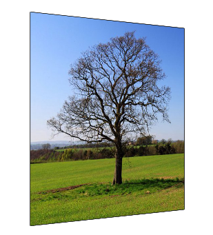
The textured quad
Now that the texture is defined, it can be put into a material palette, which would give you more options for applying textures. For example, to apply one or more textures to only certain faces of a shell, the texture must be in a material palette.
Bump Mapping
Bump mapping is a technique that is used to simulate 3D bumps or ridges upon a textured surface in order to make the surface appear more realistic. The actual object is not changed geometrically. A special image called a bump map or height map is used to define the height and location of the bumps. In the bump image, larger color values indicate higher bumps in the composite image. During lighting calculations, HOOPS Visualize Desktop uses the bump map to slightly disturb the surface normals of the object in order to achieve this effect. Since the effect depends on surface normals, lighting must be enabled in order to make bump mapping work.
To use bump mapping, load and define the diffuse texture as shown above. Then, load and define the bump map as a second texture. When the textures are applied using SetFaceTexture, specify the channel that corresponds to each texture.
    mySegmentKey.GetMaterialMappingControl().SetFaceTexture("my_texture", HPS::Material::Texture::Channel::DiffuseTexture);
    mySegmentKey.GetMaterialMappingControl().SetFaceTexture("my_bump_map", HPS::Material::Texture::Channel::Bump);

    mySegmentKey.InsertDistantLight(Vector(0, 1, 0));
mySegmentKey.GetMaterialMappingControl().SetFaceTexture("my_texture", HPS.Material.Texture.Channel.DiffuseTexture);
mySegmentKey.GetMaterialMappingControl().SetFaceTexture("my_bump_map", HPS.Material.Texture.Channel.Bump);

mySegmentKey.InsertDistantLight(new HPS.Vector(0, 1, 0));
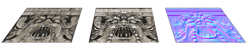
A diffuse texture (left) combined with a height map (right) creates a bumped texture (center)
The same effect can be achieved using a material palette. Likewise, a bump map can also be set in a material kit, as shown below:
    materialKitArray[0].SetDiffuseColor(HPS::RGBAColor(1, 0, 0, 1));
    materialKitArray[1].SetDiffuseTexture("my_texture"); // this material is now a texture
    materialKitArray[1].SetBump("my_bump_map"); // setting the bump component
    materialKitArray[2].SetDiffuseColor(HPS::RGBAColor(1, 0, 0, 0));
materialKit[0].SetDiffuseColor(new HPS.RGBAColor(1, 0, 0, 1));
materialKit[1].SetDiffuseTexture("my_texture");              // this material is now a texture
materialKit[1].SetBump("my_bump_map");                       // setting the bump component
materialKit[2].SetDiffuseColor(new HPS.RGBAColor(1, 0, 0, 0));
Environment Mapping
Environment mapping is a technique that uses a texture to simulate a reflection on a surface. Although some realism is sacrificed, this reflective mapping is much more efficient than traditional ray-tracing in which color is computed using a projected ray. As described in the table at the top of the page, environment mapping uses the HPS::Material::Texture::Channel::EnvironmentTexture channel.
The following example demonstrates how to setup an environment map:
    // when loading the environment texture, use "ReflectionVector" paramaterization
    textureOptionsKit.SetParameterizationSource(HPS::Material::Texture::Parameterization::ReflectionVector);

    // ... load texture

    // set texture channel to environment
    mySegmentKey.GetMaterialMappingControl().SetFaceTexture("my_texture", HPS::Material::Texture::Channel::EnvironmentTexture);
// when loading the environment texture, use "ReflectionVector" paramaterization
textureOptionsKit.
	SetParameterizationSource(HPS.Material.Texture.Parameterization.ReflectionVector);

// ... load texture

// set texture channel to environment
mySegmentKey.GetMaterialMappingControl()
	.SetFaceTexture("my_texture", HPS.Material.Texture.Channel.EnvironmentTexture);
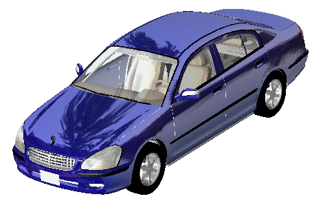
An environment map used on a model of a car
NOTE: Environment mapping uses face normals to generate the appropriate color to apply on each area of the geometry. For this reason, using environment mapping on a surface with few faces does not give a good result because the surface will have only a few normal values.
Decals
HOOPS Visualize Desktop supports texture decals. When this setting is used, any transparent portions of the texture show the underlying diffuse color, rather than making the entire material transparent. HOOPS Visualize Desktop expects that the decal image will be mapped to vertex coordinates the same way that a normal texture is.
textureOptionsKit.SetDecal(true);
textureOptionsKit.SetDecal(true);
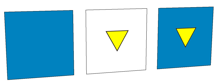
Textures on some quads demonstrating decaled surfaces
In this image, the first quad is untextured (to show the diffuse color). The middle quad is textured, however, the diffuse color is not visible because SetDecal has not been called. This causes the face of the polygon to be transparent because HOOPS Visualize Desktop draws the face with a normal, non-decaled texture. The third quad shows a properly decaled surface.