IMeshShape
Functions
Detailed Description
-
class
IMeshShape: public RED::IREDObject This interface gives access to the mesh’s properties.
@related Mesh Shapes, Building Basic Primitives, class RED::IShape
Meshes are built using indexed triangle lists. The mesh only uses triangle primitives. Strips and fans may be inserted in the mesh using the RED::IMeshShape::AddStrips and RED::IMeshShape::AddFans methods, however, they are internally broken down into triangles as this provides a better overall rendering performances in minimizing the number of rendering calls needed to draw the mesh.
A mesh has 16 data channels that can store 1 to 4 components of any RED::MESH_FORMAT kind. These data channels are used by the rendering shaders as source for their lighting calculations.
A mesh can source its data from external memory arrays. It does not necessarily own a copy of the data it draws. See the RED::IMeshShape::SetSharedArray and RED::IMeshShape::SetSharedTriangles for details on data sharing. Shared data can be used to bypass the REDsdk transaction system to save memory during dynamic edition of large datasets. Shared data are not saved to .red files. During the .red file save process, each shared array is natively saved in the shape’s data.
Public Functions
-
SET_CID(CID_class_REDIMeshShape)
-
virtual RED_RC
GetVerticesCount(int &oCount, int iStateNumber = -1) const = 0 Gets the number of vertices in the mesh.
Returns the number of vertices in the mesh. Each used data channel is sized to contain information for the same number of vertices.
See also \ref bk_pointcloud.
Parameters: - oCount – The number of vertices in the mesh.
- iStateNumber – Queried state number.
Returns: RED_OK when the operation has succeeded,
RED_BAD_PARAM if the method has received an invalid parameter.
-
virtual RED_RC
GetVertexArray(const void *&oArray, int &oSize, RED::MESH_FORMAT &oFormat, int iStateNumber = -1) const = 0 Read-only access to the vertex array of the mesh.
Returns the vertex array of the mesh, and its size and type of data per vertex. If this mesh is intended for use with the ray-tracer, it expects three MFT_FLOAT coordinates.
See also \ref bk_pointcloud.
Parameters: - oArray – Address of the vertex array of the mesh. Returns NULL if the mesh has no bound vertex array yet. The returned data is for read access only.
- oSize – Number of coordinates per vertex (1,2,3, or 4).
- oFormat – Format of the returned data.
- iStateNumber – Queried state number.
Returns: RED_OK when the operation has succeeded,
RED_BAD_PARAM if the method has received an invalid parameter.
-
virtual RED_RC
GetVertexArray(void *&oArray, int &oSize, RED::MESH_FORMAT &oFormat, const RED::State &iState) = 0 Read-write access to the vertex array of the mesh.
Returns the current vertex array of the mesh, its size and type of data per vertex. If this mesh is intended for use with the ray-tracer, it expects three MFT_FLOAT coordinates. The data array can be modified, but the format and size of the array can’t be changed.
See also \ref bk_pointcloud.
Parameters: - oArray – Address of the vertex array of the mesh. Returns NULL if the mesh has no bound vertex array yet. The returned data is for read access only.
- oSize – Number of coordinates per vertex (1,2,3, or 4).
- oFormat – Format of the returned data.
- iState – Current transaction.
Returns: RED_OK when the operation has succeeded,
RED_BAD_PARAM if the method has received an invalid parameter.
-
virtual RED_RC
GetNormalArray(const void *&oArray, int &oSize, RED::MESH_FORMAT &oFormat, int iStateNumber = -1) const = 0 Read-only access to the normal array of the mesh.
Returns the normal array of the mesh, and its size and type of data per vertex. If this mesh is intended for use with the ray-tracer, it expects three MFT_FLOAT coordinates.
See also \ref bk_improving_cad_graphics.
Parameters: - oArray – Address of the normal array of the mesh. Returns NULL if the mesh has no bound normal array. The returned data is for read access only.
- oSize – Number of coordinates per vertex (1,2,3, or 4).
- oFormat – Format of the returned data.
- iStateNumber – Queried state number.
Returns: RED_OK when the operation has succeeded,
RED_BAD_PARAM if the method has received an invalid parameter.
-
virtual RED_RC
GetNormalArray(void *&oArray, int &oSize, RED::MESH_FORMAT &oFormat, const RED::State &iState) = 0 Read-write access to the normal array of the mesh.
Returns the normal array of the mesh, and its size and type of data per vertex. If this mesh is intended for use with the ray-tracer, it expects three MFT_FLOAT coordinates.
See also \ref bk_improving_cad_graphics.
Parameters: - oArray – Address of the normal array of the mesh. Returns NULL if the mesh has no bound normal array. The returned data is for read / write access.
- oSize – Number of coordinates per vertex (1,2,3, or 4).
- oFormat – Format of the returned data.
- iState – Current transaction.
Returns: RED_OK when the operation has succeeded,
RED_BAD_PARAM if the method has received an invalid parameter.
-
virtual RED_RC
GetColorArray(const void *&oArray, int &oSize, RED::MESH_FORMAT &oFormat, int iStateNumber = -1) const = 0 Read-only access to the color array of the mesh.
Returns the color array of the mesh, and its size and type of data per vertex. This channel is not used by the ray-tracer.
Parameters: - oArray – The address of the color array of the mesh. Returns NULL if the mesh has no bound color array. The returned data is for read access only.
- oSize – Number of coordinates per vertex (1,2,3, or 4).
- oFormat – Format of the returned data.
- iStateNumber – Queried state number.
Returns: RED_OK when the operation has succeeded,
RED_BAD_PARAM if the method has received an invalid parameter.
-
virtual RED_RC
GetColorArray(void *&oArray, int &oSize, RED::MESH_FORMAT &oFormat, const RED::State &iState) = 0 Read-write access to the color array of the mesh.
Returns the color array of the mesh, and its size and type of data per vertex. This channel is not used by the ray-tracer.
Parameters: - oArray – The address of the color array of the mesh. Returns NULL if the mesh has no bound color array. The returned data is for read / write access.
- oSize – Number of coordinates per vertex (1,2,3, or 4).
- oFormat – Format of the returned data.
- iState – Current transaction.
Returns: RED_OK when the operation has succeeded,
RED_BAD_PARAM if the method has received an invalid parameter.
-
virtual RED_RC
GetTextureArray(const void *&oArray, int &oSize, RED::MESH_FORMAT &oFormat, int iTexNum, int iStateNumber = -1) const = 0 Read-only access to a texture coordinates array of the mesh.
Returns one of the texture coordinates array of the mesh, its size and type of data per vertex. These channels may be used by the ray- tracer, that accepts all combinations of size and type.
Parameters: - oArray – The address of the corresponding texture coordinate array of the mesh. Returns NULL if the mesh has no bound texture coordinate array. The returned data is for read access only.
- oSize – Number of coordinates per vertex (1,2,3, or 4).
- oFormat – Format of the returned data.
- iTexNum – Number of the texture coordinate channel in [0-7].
- iStateNumber – Queried state number.
Returns: RED_OK when the operation has succeeded,
RED_BAD_PARAM if the method has received an invalid parameter.
-
virtual RED_RC
GetTextureArray(void *&oArray, int &oSize, RED::MESH_FORMAT &oFormat, int iTexNum, const RED::State &iState) = 0 Read-write access to a texture coordinates array of the mesh.
Returns one of the texture coordinates array of the mesh, its size and type of data per vertex. These channels may be used by the ray- tracer, that accepts all combinations of size and type.
Parameters: - oArray – The address of the corresponding texture coordinate array of the mesh. Returns NULL if the mesh has no bound texture coordinate array. The returned data is for read / write access.
- oSize – Number of coordinates per vertex (1,2,3, or 4).
- oFormat – Format of the returned data.
- iTexNum – Number of the texture coordinate channel in [0-7].
- iState – Current transaction.
Returns: RED_OK when the operation has succeeded,
RED_BAD_PARAM if the method has received an invalid parameter.
-
virtual RED_RC
GetUserArray(const void *&oArray, int &oSize, RED::MESH_FORMAT &oFormat, int iUserNum, int iStateNumber = -1) const = 0 Read-only access to an user array of the mesh.
Returns one of the user arrays of the mesh, its size and type of data per vertex. These channels are not used by the ray-tracer.
Parameters: - oArray – The address of the corresponding user coordinate array of the mesh. Returns NULL if the mesh has no bound user coordinate array. The returned data is for read access only.
- oSize – Number of coordinates per vertex (1,2,3, or 4).
- oFormat – Format of the returned data.
- iUserNum – Number of the user channel in [0-3].
- iStateNumber – Queried state number.
Returns: RED_OK when the operation has succeeded,
RED_BAD_PARAM if the method has received an invalid parameter.
-
virtual RED_RC
GetUserArray(void *&oArray, int &oSize, RED::MESH_FORMAT &oFormat, int iUserNum, const RED::State &iState) = 0 Read-write access to an user array of the mesh.
Returns one of the user arrays of the mesh, its size and type of data per vertex. These channels are not used by the ray-tracer.
Parameters: - oArray – The address of the corresponding user coordinate array of the mesh. Returns NULL if the mesh has no bound user coordinate array. The returned data is for read / write access.
- oSize – Number of coordinates per vertex (1,2,3, or 4).
- oFormat – Format of the returned data.
- iUserNum – Number of the user channel in [0-3].
- iState – Current transaction.
Returns: RED_OK when the operation has succeeded,
RED_BAD_PARAM if the method has received an invalid parameter.
-
virtual RED_RC
GetArray(const void *&oArray, int &oSize, RED::MESH_FORMAT &oFormat, RED::MESH_CHANNEL iChannelId, int iStateNumber = -1) const = 0 Read-only access an array through its channel identifier.
Returns the array whose channel identifier is ‘iChannelId’.
Parameters: - oArray – The address of the array in the mesh. Returns NULL if the mesh has no data in that array. The returned data is for read access only.
- oSize – Number of coordinates per vertex (1,2,3, or 4).
- oFormat – Format of the returned data.
- iChannelId – Requested channel id.
- iStateNumber – Queried state number.
Returns: RED_OK when the operation has succeeded,
RED_BAD_PARAM if the method has received an invalid parameter.
-
virtual RED_RC
GetArray(void *&oArray, int &oSize, RED::MESH_FORMAT &oFormat, RED::MESH_CHANNEL iChannelId, const RED::State &iState) = 0 Read-write access an array through its channel identifier.
Returns the array whose channel identifier is ‘iChannelId’.
See also \ref bk_pointcloud.
Parameters: - oArray – The address of the array in the mesh. Returns NULL if the mesh has no data in that array. The returned data is for read / write access.
- oSize – Number of coordinates per vertex (1,2,3, or 4).
- oFormat – Format of the returned data.
- iChannelId – Requested channel id.
- iState – Current transaction.
Returns: RED_OK when the operation has succeeded,
RED_BAD_PARAM if the method has received an invalid parameter.
-
virtual RED_RC
GetArray(const void *&oData, RED::MESH_CHANNEL iChannelId, int iStateNumber = -1) const = 0 Read-only access an array data through its channel identifier.
Returns the data in the array whose channel id is ‘iChannelId’.
See also \ref bk_pointcloud.
Parameters: - oData – Address of the array in the mesh. Returns NULL if the mesh has no data in that array. The returned data is for read access only.
- iChannelId – Requested channel id.
- iStateNumber – Queried state number.
Returns: RED_OK when the operation has succeeded,
RED_BAD_PARAM if the method has received an invalid parameter.
-
virtual RED_RC
GetArray(void *&oData, RED::MESH_CHANNEL iChannelId, const RED::State &iState) = 0 Read-write access an array data through its channel identifier.
Returns the data in the array whose channel id is ‘iChannelId’.
See also \ref bk_pointcloud.
Parameters: - oData – Address of the array in the mesh. Returns NULL if the mesh has no data in that array. The returned data is for read / write access.
- iChannelId – Requested channel id.
- iState – Current transaction.
Returns: RED_OK when the operation has succeeded,
RED_BAD_PARAM if the method has received an invalid parameter.
Is the specified channel being shared?
Parameters: - oShared – true if the data in ‘iChannelId’ is shared. false otherwise (not shared or no data).
- iChannelId – Identifier of the channel to check.
- iStateNumber – Queried state number.
Returns: RED_OK if the operation has succeeded,
RED_BAD_PARAM if the method has received an invalid parameter.
-
virtual RED_RC
GetTriangles(const int *&oTriIndex, int &oTriCount, int iStateNumber = -1) const = 0 Read-only access to the list of triangles in the mesh.
Returns the list of triangle sets in the mesh (isolated triangles). Each triangle is made of three or six consecutive entries in ‘oTriIndex’, for a total of 3 (or 6) * ‘oTriCount’ entries. The number of entries for a triangle is 3 by default, unless adjacency informations have been supplied, in which case, the number is 6. See RED::IMeshShape::IsTrianglesAdjacency for the query over the mesh data format.
An index value indicates the number of the vertex to access in the mesh arrays.
See also \ref wf_viewport_shading.
Parameters: - oTriIndex – Triangle index list.
- oTriCount – Number of triangles.
- iStateNumber – Queried state number.
Returns: RED_OK when the operation has succeeded,
RED_BAD_PARAM if the method has received an invalid parameter.
-
virtual RED_RC
GetTriangles(int *&oTriIndex, int &oTriCount, const RED::State &iState) = 0 Read-write access to the list of triangles in the mesh.
Returns the list of triangle sets in the mesh (isolated triangles). Each triangle is made of three or six consecutive entries in ‘oTriIndex’, for a total of 3 (or 6) * ‘oTriCount’ entries. The number of entries for a triangle is 3 by default, unless adjacency informations have been supplied, in which case, the number is 6. See RED::IMeshShape::IsTrianglesAdjacency for the query over the mesh data format.
An index value indicates the number of the vertex to access in the mesh arrays.
See also \ref wf_viewport_shading.
Parameters: - oTriIndex – Triangle index list.
- oTriCount – Number of triangles.
- iState – Current transaction.
Returns: RED_OK when the operation has succeeded,
RED_BAD_PARAM if the method has received an invalid parameter.
-
virtual RED_RC
GetTrianglesCount(int &oCount, int iStateNumber = -1) const = 0 Returns the number of triangles in the mesh.
See also \ref wf_viewport_shading.
Parameters: - oCount – The number of triangles in the mesh.
- iStateNumber – Queried state number.
Returns: RED_OK when the operation has succeeded,
RED_BAD_PARAM if the method has received an invalid parameter.
Is the mesh’s triangle array being shared?
Parameters: - oShared – true if the object triangle list is shared. false otherwise (not shared or no data).
- iStateNumber – Queried state number.
Returns: RED_OK if the operation has succeeded,
RED_BAD_PARAM if the method has received an invalid parameter.
-
virtual RED_RC
IsTrianglesAdjacency(bool &oAdjacency, int iStateNumber = -1) const = 0 Are mesh triangles using adjacency?
Adjacency can be specified for the mesh using RED::IMeshShape::AddTrianglesAdjacency.
Parameters: - oAdjacency – true if the mesh stores triangles with adjacency.
- iStateNumber – Queried state number.
Returns: RED_OK if the operation has succeeded,
RED_BAD_PARAM if the method has received an invalid parameter.
-
virtual RED_RC
SetArray(RED::MESH_CHANNEL iChannelId, const void *iData, int iVerticesCount, int iSize, RED::MESH_FORMAT iFormat, const RED::State &iState) = 0 Defines the contents of a data channel.
This method defines the contents of the targeted channel. We have two possible memory behaviors here:
- Copy the provided input data in the class. We try to be memory conservative in this case and to reuse existing memory that could have been allocated earlier on for the same data channel.
- Provide no ‘iData’ at all. In this case, we allocate an array using the dimension parameters provided. This array is not initialized by the call, and can be accessed to be filled.
Note that we define the number of vertices as a parameter of the method, to be able to figure out the total size of our data channel. All channels must be configured with the same number of vertices. The method fails if the provided number of vertices don’t match the current size of other channels.
See also \ref bk_pointcloud.
Parameters: - iChannelId – Targeted channel that’ll receive the contents of ‘iData’.
- iData – Data array. NULL to let the method allocate an array itself.
- iVerticesCount – Number of vertices for all channels.
- iSize – Number of coordinates per vertex in [1-4].
- iFormat – Format of each coordinate.
- iState – Current transaction.
Returns: RED_OK when the data channel could have been defined,
RED_BAD_PARAM if the method has received an invalid parameter,
RED_ALLOC_FAILURE if an internal allocation has failed,
RED_FAIL if the number of vertices does not match the current size of other channels.
Defines the contents of a data channel.
This method is similar to RED::IMeshShape::SetArray, except that the memory control of the provided array is let to the caller’s responsibility. Shared arrays differ in their behaviors from regular arrays in several ways:
- The address of a shared array do not change with new transactions. A regular array is copied to a new version when modified so that it can be modified without stalling a multi-threaded rendering that may occur on the last closed transaction version of the data. A shared array is not duplicated and therefore the returned address can’t be overwritten if multi-threaded rendering is used.
- RED::IMeshShape::DeleteArray and RED::IMeshShape::DeleteAllArrays don’t release the shared memory but behave normally for all other aspects of the method.
- RED::IMeshShape::BuildTangents can’t target a data channel used by a shared array.
Note that an array that is shared among different shapes will still be uploaded many times on the video memory except if it’s declared as a batch array on the material using RED::IMaterial::AddBatchArrays.
Parameters: - iChannelId – Targeted channel.
- iData – Shared data array.
- iVerticesCount – Number of vertices for all channels.
- iSize – Number of coordinates per vertex in [1-4].
- iFormat – Format of each coordinate.
- iState – Current transaction.
Returns: RED_OK when the data channel could have been shared,
RED_BAD_PARAM if the method has received an invalid parameter,
RED_ALLOC_FAILURE if an internal allocation has failed,
RED_FAIL if the number of vertices does not match the current size of other channels.
-
virtual RED_RC
SetOwnedArray(RED::MESH_CHANNEL iChannelId, const void *iData, int iVerticesCount, int iSize, RED::MESH_FORMAT iFormat, const RED::State &iState) = 0 Force an array list for the object.
This method bypasses the REDsdk transaction system. Use with care. It directly sets the address of the object’s specified array list in the last transaction container of the object (e.g. the RED::State::GetZeroState). Memory must have been managed using rmalloc / rrealloc / rfree. The method does not release any memory prior to have its memory storage overriden.
This method can be used to do ‘in place’ memory operations in thread safe areas of the rendering pipeline.
Arrays can’t be shared before the method is called. The array is owned by the object after the call. The number of vertices can temporarily differ among arrays of the shape while performing changes.
Parameters: - iChannelId – Targeted channel.
- iData – The data array address.
- iVerticesCount – Number of vertices for all channels.
- iSize – Number of coordinates per vertex in [1-4].
- iFormat – Format of each coordinate.
- iState – Current transaction.
Returns: RED_OK if the method could succeed,
RED_BAD_PARAM if the method has received an invalid parameter,
-
virtual RED_RC
DeleteArray(RED::MESH_CHANNEL iChannelId, const RED::State &iState) = 0 Deletes the contents of a data channel.
This method deletes the contents of a data channel identified by its number in the object. The corresponding array - if found - is freed from memory.
Parameters: - iChannelId – Id of the channel to release.
- iState – Current transaction.
Returns: RED_OK when the channel’s data could be released,
RED_BAD_PARAM if the method has received an invalid parameter,
RED_ALLOC_FAILURE if an internal allocation has failed,
RED_FAIL otherwise.
-
virtual RED_RC
DeleteAllArrays(const RED::State &iState) = 0 Deletes the contents of all data channels.
Works as RED::IMeshShape::DeleteArray, for all channels in the object.
Parameters: iState – Current transaction. Returns: RED_OK when the channel’s data could be released, RED_BAD_PARAM if the method has received an invalid parameter,
RED_ALLOC_FAILURE if an internal allocation has failed,
RED_FAIL otherwise.
-
virtual RED_RC
AddTriangles(const int *iTriIndex, int iTriCount, const RED::State &iState) = 0 Adds triangles to the object’s list.
This method adds triangles to the list of triangles in the object. The input information is being copied and appended at the end of the existing information already set.
It’s possible to provide no triangle index array at all. In this case, the size of the triangle list is increased by ‘iNbTriangles’, and all indices in the added list are set to zero. Then the quick triangle edition method RED::IMeshShape::SetTriangle can be used to change the list on the fly, without memory allocations penalties that would occur with a 1 by 1 addition of all triangles.
If the object had a shared triangle list, this list is replaced by the data supplied to this method.
See also \ref bk_pointcloud.
Parameters: - iTriIndex – Index array for the added triangles. Contains three (int) values per triangle. Each index points to the number of the vertex to reference in the mesh data channels. When NULL, the method creates an index array set to zero by default, sized to the number of requested triangles.
- iTriCount – Number of triangles to add (must be >=0)
- iState – Current transaction.
Returns: RED_OK when the triangles could be added,
RED_BAD_PARAM if the method has received an invalid parameter,
RED_ALLOC_FAILURE if an internal memory allocation has failed,
RED_FAIL otherwise.
-
virtual RED_RC
AddTrianglesAdjacency(const int *iTriIndex, int iTriCount, const RED::State &iState) = 0 Adds triangles to the object’s list, with adjacency informations.
This method adds triangles to the list of triangles in the object. The input information is being copied and appended at the end of the existing information already set.
It’s possible to provide no triangle index array at all. In this case, the size of the triangle list is increased by ‘iNbTriangles’, and all indices in the added list are set to zero. Then the quick triangle edition method RED::IMeshShape::SetTriangleAdjacency can be used to change the list on the fly, without memory allocations penalties that would occur with a 1 by 1 addition of all triangles.
If the object had a shared triangle list, this list is replaced by the data supplied to this method.
Triangles with adjacency are defined as indicated below:
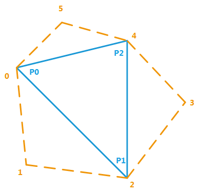
Each mesh triangle must be defined with three adjacent vertices. The triangle is [ P0, P1, P2 ] and the set of 6 vertices 0, 1, 2, 3, 4, 5 are supplied to the method for each triangle, 0 being P0, 2 being P1 and 4 being P2.
Parameters: - iTriIndex – Index array for the added triangles. Contains six (int) values per triangle. Each index points to the number of the vertex to reference in the mesh data channels. When NULL, the method creates an index array set to zero by default, sized to the number of requested triangles.
- iTriCount – Number of triangles to add (must be >=0)
- iState – Current transaction.
Returns: RED_OK when the triangles could be added,
RED_BAD_PARAM if the method has received an invalid parameter,
RED_ALLOC_FAILURE if an internal memory allocation has failed,
RED_FAIL otherwise.
-
virtual RED_RC
SetTriangle(int iNumTri, int iP0, int iP1, int iP2, const RED::State &iState) = 0 Modifies indices defining a triangle.
This method can be used to quickly change the indices defining a triangle. The target triangle is ‘iNumTri’, and the new indices to use for it are [ iP0, iP1, iP2 ].
Parameters: - iNumTri – Triangle to modify.
- iP0 – First triangle vertex number.
- iP1 – Second triangle vertex number.
- iP2 – Third triangle vertex number.
- iState – Current transaction.
Returns: RED_OK when the operation succeeded,
RED_BAD_PARAM if the method has received an invalid parameter,
RED_ALLOC_FAILURE if an internal memory allocation has failed,
RED_FAIL otherwise.
-
virtual RED_RC
SetTriangleAdjacency(int iNumTri, int iV0, int iV1, int iV2, int iV3, int iV4, int iV5, const RED::State &iState) = 0 Modifies indices defining a triangle, with adjacency.
This method can be used to quickly change the indices defining a triangle. The target triangle is ‘iNumTri’, and the new indices to use for it are [ iV0, iV1, iV2, iV3, iV4, iV5 ].
See RED::IMeshShape::SetTrianglesAdjacency for details.
Parameters: - iNumTri – Triangle to modify.
- iV0 – First vertex number (is the first triangle vertex).
- iV1 – Second vertex number.
- iV2 – Third vertex number (is the second triangle vertex).
- iV3 – Fourth vertex number.
- iV4 – Fifth vertex number (is the third triangle vertex).
- iV5 – Sixth vertex number.
- iState – Current transaction.
Returns: RED_OK when the operation succeeded,
RED_BAD_PARAM if the method has received an invalid parameter,
RED_ALLOC_FAILURE if an internal memory allocation has failed,
RED_FAIL otherwise.
Uses a shared triangle list for the object.
If the object was owning a list of triangles, this list is deleted and replaced by the shared list provided to the method.
Parameters: - iTriIndex – Index array for the added triangles. Must point on a valid array of three (int)s for each triangle vertices indices.
- iTriCount – Number of triangles in ‘iTriIndex’.
- iState – Current transaction.
Returns: RED_OK when the operation succeeded,
RED_BAD_PARAM if the method has received an invalid parameter,
RED_ALLOC_FAILURE if an internal memory allocation has failed,
RED_FAIL otherwise.
-
virtual RED_RC
SetOwnedTriangles(const int *iTriIndex, int iTriCount, const RED::State &iState) = 0 Force the triangle list for the object.
This method bypasses the REDsdk transaction system. Use with care. It directly sets the address of the object’s triangle list and triangle count in the last transaction container of the object (e.g. the RED::State::GetZeroState). Memory must have been managed using rmalloc / rrealloc / rfree. The method does not release any memory prior to have its memory storage overriden.
This method can be used to do ‘in place’ memory operations in thread safe areas of the rendering pipeline.
Arrays can’t be shared before the method is called. The array is owned by the object after the call.
Parameters: - iTriIndex – Index array that’ll replace the shape triangles. 3 ints for each triangle.
- iTriCount – Number of triangles in ‘iTriIndex’.
- iState – Current transaction. Must be RED::State::GetZeroState.
Returns: RED_OK when the operation succeeded,
RED_BAD_PARAM if the method has received an invalid parameter,
RED_ALLOC_FAILURE if an internal memory allocation has failed,
RED_FAIL otherwise.
Uses a shared triangle list with adjacency for the object.
If the object was owning a list of triangles, this list is deleted and replaced by the shared list provided to the method.
Parameters: - iTriIndex – Index array for the added triangles. Must point on a valid array of six (int)s for each triangle vertices indices.
- iTriCount – Number of triangles in ‘iTriIndex’.
- iState – Current transaction.
Returns: RED_OK when the operation succeeded,
RED_BAD_PARAM if the method has received an invalid parameter,
RED_ALLOC_FAILURE if an internal memory allocation has failed,
RED_FAIL otherwise.
-
virtual RED_RC
SetOwnedTrianglesAdjacency(const int *iTriIndex, int iTriCount, const RED::State &iState) = 0 Force the triangle list for the object.
Same as RED::IMeshShape::SetOwnedTriangles, but with adjacency.
Parameters: - iTriIndex – Index array that’ll replace the shape triangles. 6 ints for each triangle.
- iTriCount – Number of triangles in ‘iTriIndex’.
- iState – Current transaction. Must be RED::State::GetZeroState.
Returns: RED_OK when the operation succeeded,
RED_BAD_PARAM if the method has received an invalid parameter,
RED_ALLOC_FAILURE if an internal memory allocation has failed,
RED_FAIL otherwise.
-
virtual RED_RC
DeleteTriangles(const RED::State &iState) = 0 Deletes all triangles in the mesh list.
This method removes all triangles from the list within the mesh. The memory formerly used is released if the list was owned by the object.
Parameters: iState – Current transaction. Returns: RED_OK when the operation succeeded, RED_BAD_PARAM if the method has received an invalid parameter,
RED_ALLOC_FAILURE if an internal memory allocation has failed,
RED_FAIL otherwise.
-
virtual RED_RC
AddStrips(const int *iStripIndex, const int *iStripCount, int iStripEntriesCount, const RED::State &iState) = 0 Adds triangle strips to the object contents.
This method adds triangles strips to the list of triangles in the object. The input information is being turned into triangles, then copied and appended at the end of the existing information set.
Calling this method replaces any shared triangle list that was stored in the object.
See also \ref wf_building_basic_primitives.
Parameters: - iStripIndex – Indices of all strips in sequence. If for example, there are two strips added of length 4 and 5, then ‘iStripIndex’ should contain 9 floats referencing vertices numbers in the data channels of the object. For example, (0,1,2,3,8,9,10,11,12) is a valid content defining two strips of length 4 and 5.
- iStripCount – Contains the list of number of vertices of each strip. Using the previous example, ‘iStripCount’ contains only two values set to 4 and 5.
- iStripEntriesCount – Number of added strips. Still in our example, 2.
- iState – Current transaction.
Returns: RED_OK when the operation succeeded,
RED_BAD_PARAM if the method has received an invalid parameter,
RED_ALLOC_FAILURE if an internal memory allocation has failed,
RED_FAIL otherwise.
-
virtual RED_RC
AddFans(const int *iFanIndex, const int *iFanCount, int iFanEntriesCount, const RED::State &iState) = 0 Adds triangle fans to the object contents.
This method adds triangles fans to the list of fans in the object. The input information is being turned into triangles, then copied and appended at the end of the existing information set.
Calling this method replaces any shared triangle list that was stored in the object.
Parameters: - iFanIndex – Indices of all fans in sequence. If there are two fans added of length 4 and 5, then ‘iFanIndex’ should contain 9 floats referencing vertices numbers in the data channels of the object. For example, (0,1,2,3,8,9,10,11,12) is a valid content defining two fans of length 4 and 5.
- iFanCount – Contains the list of number of vertices of each fan. Using the previous example, ‘iFanCount’ contains only two values set to 4 and 5.
- iFanEntriesCount – Number of added fans. Still in our example, 2.
- iState – Current transaction.
Returns: RED_OK when the operation succeeded,
RED_BAD_PARAM if the method has received an invalid parameter,
RED_ALLOC_FAILURE if an internal memory allocation has failed,
RED_FAIL otherwise.
-
virtual RED_RC
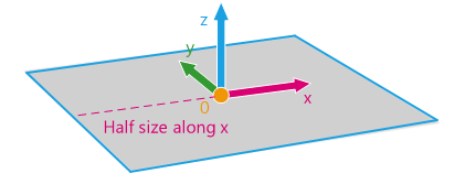
Quad(const RED::Vector3 &iCenter, float iHalfSizeX, float iHalfSizeY, const RED::State &iState) = 0 Creates a quad shape.
This method creates a quad shape. It sets vertices, normal and texture coordinates informations filling RED::MCL_VERTEX, RED::MCL_NORMAL and RED::MCL_TEX0 channels. The quad lays along the x and y axis, its normal is along the z axis.
Texture coordinates are built using a planar projection (see RED::MTCM_PLANAR). Corner (-x,-y) receive (0,0) as texture coordinates, corner (+x,-y) receives (1,0), corner (-x,+y) receives (0,1) and corner (+x,+y) receives (1,1).
If the shape already contains data, they are overridden.
See also \ref wf_hello_world.
Parameters: - iCenter – Quad center.
- iHalfSizeX – Half size of the quad along the x axis. Must be strictly positive.
- iHalfSizeY – Half size of the quad along the y axis. Must be strictly positive.
- iState – Current transaction.
Returns: RED_OK when the operation succeeded,
RED_BAD_PARAM if the method has received an invalid parameter,
RED_ALLOC_FAILURE if an internal memory allocation has failed,
RED_FAIL otherwise.
-
virtual RED_RC
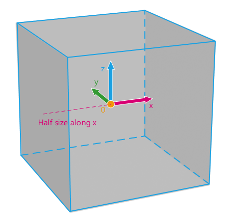
Box(const RED::Vector3 &iCenter, const RED::Vector3 &iHalfSize, const RED::State &iState) = 0 Creates a box shape.
This method creates a box shape. It sets vertices, normal and texture coordinates informations filling RED::MCL_VERTEX, RED::MCL_NORMAL and RED::MCL_TEX0 channels.
The texture coordinates are built using a box projection (see RED::MTCM_BOX).
If the shape already contains data, they are overridden.
See also \ref wf_rendering_large_images.
Parameters: - iCenter – Center of the box.
- iHalfSize – Half size of the box in the three axis. Must be strictly positive.
- iState – Current transaction.
Returns: RED_OK when the operation succeeded,
RED_BAD_PARAM if the method has received an invalid parameter,
RED_ALLOC_FAILURE if an internal memory allocation has failed,
RED_FAIL otherwise.
-
virtual RED_RC
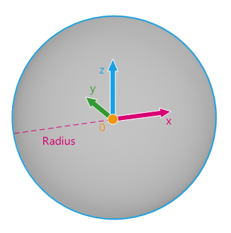
Sphere(const RED::Vector3 &iCenter, float iRadius, int iRDivCount, int iHDivCount, const RED::State &iState) = 0 Creates a sphere shape.
This method creates a sphere shape. It sets vertices, normal and texture coordinates informations filling RED::MCL_VERTEX, RED::MCL_NORMAL and RED::MCL_TEX0 channels.
The texture coordinates are built using a spherical projection (see RED::MTCM_SPHERICAL).
If the shape already contains data, they are overridden.
The number of circular and horizontal subdivisions for this primitive have to be greater than or equal to 3 unless a RED_BAD_PARAM error will be returned.
See also \ref wf_cartoon_shading.
Parameters: - iCenter – Center position of the sphere.
- iRadius – Radius of the sphere. Must be strictly positive.
- iRDivCount – Number of circular subdivisions. Must be greater than or equal to 3.
- iHDivCount – Number of horizontal subdivisions. Must be greater than or equal to 3.
- iState – Current transaction.
Returns: RED_OK when the operation succeeded,
RED_BAD_PARAM if the method has received an invalid parameter,
RED_ALLOC_FAILURE if an internal memory allocation has failed,
RED_FAIL otherwise.
-
virtual RED_RC
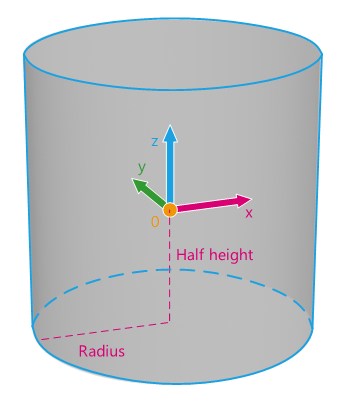
Cylinder(const RED::Vector3 &iCenter, float iRadius, float iHalfHeight, int iRDivCount, const RED::State &iState) = 0 Creates a cylinder shape.
This method creates a cylinder shape. It sets vertices, normal and texture coordinates informations filling RED::MCL_VERTEX, RED::MCL_NORMAL and RED::MCL_TEX0 channels. The cylinder is built along the z axis.
The texture coordinates are built using a cylinder cap projection (see RED::MTCM_CYLINDER_CAP).
If the shape already contains data, they are overridden.
The number of circular subdivisions for this primitive have to be greater than or equal to 3 unless a RED_BAD_PARAM error will be returned.
See also \ref wf_outdoor_lighting.
Parameters: - iCenter – Center position of the cylinder.
- iRadius – Radius of the cylinder. Must be strictly positive.
- iHalfHeight – Half height of the cylinder. Must be strictly positive.
- iRDivCount – Number of circular subdivisions. Must be greater than or equal to 3.
- iState – Current transaction.
Returns: RED_OK when the operation succeeded,
RED_BAD_PARAM if the method has received an invalid parameter,
RED_ALLOC_FAILURE if an internal memory allocation has failed,
RED_FAIL otherwise.
-
virtual RED_RC
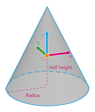
Cone(const RED::Vector3 &iCenter, float iRadius, float iHalfHeight, int iRDivCount, const RED::State &iState) = 0 Creates a cone shape.
This method creates a cone shape. It sets vertices, normal and texture coordinates informations filling RED::MCL_VERTEX, RED::MCL_NORMAL and RED::MCL_TEX0 channels. The cone is built along the z axis.
The texture coordinates are built using a cylinder cap projection (see RED::MTCM_CYLINDER_CAP).
If the shape already contains data, they are overridden.
The number of circular subdivisions for this primitive have to be greater than or equal to 3 unless a RED_BAD_PARAM error will be returned.
See also \ref wf_cartoon_shading.
Parameters: - iCenter – Center position of the cone.
- iRadius – Radius of the cone. Must be strictly positive.
- iHalfHeight – Half height of the cone. Must be strictly positive.
- iRDivCount – Number of circular subdivisions. Must be greater than or equal to 3.
- iState – Current transaction.
Returns: RED_OK when the operation succeeded,
RED_BAD_PARAM if the method has received an invalid parameter,
RED_ALLOC_FAILURE if an internal memory allocation has failed,
RED_FAIL otherwise.
-
virtual RED_RC
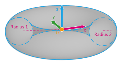
Torus(const RED::Vector3 &iCenter, float iRadius, float iRadius2, int iDivCount, int iDivCount2, const RED::State &iState) = 0 Creates a torus shape.
This method creates a torus shape. It sets vertices, normal and texture coordinates informations filling RED::MCL_VERTEX, RED::MCL_NORMAL and RED::MCL_TEX0 channels. The torus is built around the z axis.
The texture coordinates are built using a spherical projection (see RED::MTCM_SPHERICAL).
If the shape already contains data, they are overridden.
The number of circular subdivisions for this primitive have to be greater than or equal to 3 unless a RED_BAD_PARAM error will be returned. The mesh is an open wrapped skin which is closed, but that has a revolving circular border on the z = 0 plane and on the y = 0 plane. You can see this border if you create border edges on a torus for instance.
See also \ref wf_cartoon_shading.
Parameters: - iCenter – Center position of the torus.
- iRadius – Radius of the torus. Must be strictly positive.
- iRadius2 – Second radius of the torus. Must be strictly positive.
- iDivCount – Number of circular subdivisions. Must be greater than or equal to 3.
- iDivCount2 – Number of secondary circular subdivisions. Must be greater than or equal to 3.
- iState – Current transaction.
Returns: RED_OK when the operation succeeded,
RED_BAD_PARAM if the method has received an invalid parameter,
RED_ALLOC_FAILURE if an internal memory allocation has failed,
RED_FAIL otherwise.
-
virtual RED_RC
Polygon(const RED::Vector<RED::Vector<double>> &iContourList, const RED::State &iState) = 0 Creates a planar polygon from a set of contours.
This method creates the tessellation of a polygon defined by the specififed iContourList. The method tessellates all the specified contours and sets the mesh contents with the resulting triangles generated by the tessellation.
This method can use several contours for the definition of the polygon. Each contour that has a counter clockwise (CCW) orientation is triangulated inside. Each contour that has a clockwise (CW) orientation defines an outer region of the polygon. So a CW polygon inside a CCW polygon defines a hole in the resulting tessellated face.
The resulting polygon is stored using double precision floating point data.
Parameters: - iContourList – Input list of vertices (xyz xyz xyz…) for each contour. We use a ODD winding rule to determine inside / outside regions of the polygon. The method uses double precision vertices.
- iState – Current transaction.
Returns: RED_OK if the operation has succeeded,
RED_BAD_PARAM if the method has received an incorrect vertex array,
RED_ALLOC_FAILURE if an internal memory allocation has failed,
RED_FAIL otherwise.
-
virtual RED_RC
Polygon(const RED::Vector<RED::Vector<float>> &iContourList, const RED::State &iState) = 0 Creates a planar polygon from a set of contours.
This method behaves as the other RED::IMeshShape::Polygon, but uses simple precision floating point values.
The resulting polygon is stored using simple precision floating point data.
See also \ref wf_picking_using_a_lasso.
Parameters: - iContourList – Input list of vertices (xyz xyz xyz…) for each contour. We use a ODD winding rule to determine inside / outside regions of the polygon. The method uses double precision vertices.
- iState – Current transaction.
Returns: RED_OK if the operation has succeeded,
RED_BAD_PARAM if the method has received an incorrect vertex array,
RED_ALLOC_FAILURE if an internal memory allocation has failed,
RED_FAIL otherwise.
-
virtual RED_RC
Polygon(RED::Vector<double> &oVertexData, const RED::Vector<RED::Vector<double>> &iContourList, const RED::Vector<RED::Vector<double>> &iContourDataList, RED::POLYGON_WINDING_RULE iWindingRule, const RED::Vector3 &iNormal, const RED::State &iState) = 0 Creates a planar polygon from a set of contours.
This method behaves as the other RED::IMeshShape::Polygon. In addition, it gets an array of data for each contour point and returns this data associated to the created vertices. This is usefull to associate texture coordinates or colors.
iContourDataList stores unlimited data for each contour vertex. The array size must be ( contour point count * number of double data per point ). For instance, the data can be a pair of texture coordinates.
The returned oVertexData contains for each created vertex:
- the raw iContourDataList data in case of a contour point directly becoming a vertex.
- an interpolation of the iContourDataList data in case of a new vertex creation. The size of the array is ( vertices count * number of double data per point ). The data are stored in the same way iContourDataList data are stored.
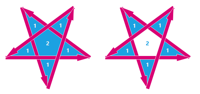
To understand how iWindingRule works, consider that the input contours partition the plane into regions. The winding rule determines which of these regions are inside the polygon.
For a single contour C, the winding number of a point x is simply the signed number of revolutions we make around x as we travel once around C (where CCW is positive). When there are several contours, the individual winding numbers are summed. This procedure associates a signed integer value with each point x in the plane. Note that the winding number is the same for all points in a single region.
The winding rule classifies a region as ‘inside’ if its winding number belongs to the chosen category (odd, nonzero, positive, negative, or absolute value of at least two).
The resulting polygon is stored using double precision floating point data.
See \ref tk_creating_a_polygon_shape for details about how to use the vertex mapping array.
The polygon normal can be specified iNormal and all vertices are projected onto the plane defined by that normal for the tessellation. If the normal is zero, then the method automatically finds out the best normal to use.
Parameters: - oVertexData – Returned vertex data corresponding to the created vertices.
- iContourList – Input list of vertices (xyz xyz xyz…) for each contour. We use a ODD winding rule to determine inside / outside regions of the polygon. The method uses double precision vertices.
- iContourDataList – Input list of vertex data for each contour.
- iWindingRule – Winding rule.
- iNormal – Polygon normal to use. Set to RED::Vector3::ZERO to let the method decides.
- iState – Current transaction.
Returns: RED_OK if the operation has succeeded,
RED_BAD_PARAM if the method has received an incorrect vertex array,
RED_ALLOC_FAILURE if an internal memory allocation has failed,
RED_FAIL otherwise.
-
virtual RED_RC
Polygon(RED::Vector<double> &oVertexData, const RED::Vector<RED::Vector<float>> &iContourList, const RED::Vector<RED::Vector<double>> &iContourDataList, RED::POLYGON_WINDING_RULE iWindingRule, const RED::Vector3 &iNormal, const RED::State &iState) = 0 Creates a planar polygon from a set of contours.
This method behaves as the other RED::IMeshShape::Polygon, but uses simple precision floating point values. In addition, it gets an array of data for each contour point and returns this data associated to the created vertices. This is usefull to associate texture coordinates or colors.
iContourDataList stores unlimited data for each contour vertex. The array size must be ( contour point count * number of double data per point ). For instance, the data can be a pair of texture coordinates.
The returned oVertexData contains for each created vertex:
- the raw iContourDataList data in case of a contour point directly becoming a vertex.
- an interpolation of the iContourDataList data in case of a new vertex creation. The size of the array is ( vertices count * number of double data per point ). The data are stored in the same way iContourDataList data are stored.
To understand how iWindingRule works, consider that the input contours partition the plane into regions. The winding rule determines which of these regions are inside the polygon.
For a single contour C, the winding number of a point x is simply the signed number of revolutions we make around x as we travel once around C (where CCW is positive). When there are several contours, the individual winding numbers are summed. This procedure associates a signed integer value with each point x in the plane. Note that the winding number is the same for all points in a single region.
The winding rule classifies a region as ‘inside’ if its winding number belongs to the chosen category (odd, nonzero, positive, negative, or absolute value of at least two).
The resulting polygon is stored using simple precision floating point data.
See \ref tk_creating_a_polygon_shape for details about how to use the vertex mapping array.
The polygon normal can be specified iNormal and all vertices are projected onto the plane defined by that normal for the tessellation. If the normal is zero, then the method automatically finds out the best normal to use.
Parameters: - oVertexData – Returned vertex data corresponding to the created vertices.
- iContourList – Input list of vertices (xyz xyz xyz…) for each contour. We use a ODD winding rule to determine inside / outside regions of the polygon. The method uses double precision vertices.
- iContourDataList – Input list of vertex data for each contour.
- iWindingRule – Winding rule.
- iNormal – Polygon normal to use. Set to RED::Vector3::ZERO to let the method decides.
- iState – Current transaction.
Returns: RED_OK if the operation has succeeded,
RED_BAD_PARAM if the method has received an incorrect vertex array,
RED_ALLOC_FAILURE if an internal memory allocation has failed,
RED_FAIL otherwise.
-
virtual RED_RC
AddBone(unsigned int &oBoneIndex, const RED::Matrix &iNeutralMatrix, int iParentBone, const RED::String &iName, const RED::State &iState) = 0 Adds a bone to the mesh skeleton.
Skeleton is mainly used for mesh skinning (see RED::IMeshShape::SetSkinBone).
Skeleton bones must be added parent-first in the bones hierarchy. This means the root bone is always the first to be added and will always have the index 0.
The iParentBone index for the root node must be set to -1.
Parameters: - oBoneIndex – Returned bone index to access the bone data later.
- iNeutralMatrix – Bone neutral matrix (Generally T-Pose or idle stance).
- iParentBone – Index of the parent bone already added (-1 for the root).
- iName – Name of the bone.
- iState – Current transaction.
Returns: RED_OK if the operation has succeeded,
RED_BAD_PARAM if bones are not added in the correct order,
RED_ALLOC_FAILURE if an internal memory allocation has failed,
RED_FAIL otherwise.
-
virtual RED_RC
GetBonesCount(unsigned int &oCount, int iStateNumber = -1) const = 0 Returns the number of bones in the skeleton.
Parameters: - oCount – Returned number of bones.
- iStateNumber – Queried state number.
Returns: RED_OK if the operation has succeeded,
RED_FAIL otherwise.
-
virtual RED_RC
SetBoneMatrix(unsigned int iBoneIndex, const RED::Matrix &iBoneMatrix, const RED::State &iState) = 0 Sets the local matrix of a bone.
The local matrix is the bone transform in its parent frame.
Parameters: - iBoneIndex – Bone index to set the matrix.
- iBoneMatrix – Bone matrix.
- iState – Current transaction.
Returns: RED_OK if the operation has succeeded,
RED_BAD_PARAM if iBoneIndex is incorrect,
RED_FAIL otherwise.
-
virtual RED_RC
GetBoneMatrix(const RED::Matrix *&oBoneMatrix, unsigned int iBoneIndex, int iStateNumber = -1) const = 0 Gets the local matrix of a bone.
Parameters: - oBoneMatrix – Returned bone matrix.
- iBoneIndex – Bone index to get the matrix from.
- iStateNumber – Queried state number.
Returns: RED_OK if the operation has succeeded,
RED_BAD_PARAM if iBoneIndex is incorrect,
RED_FAIL otherwise.
-
virtual RED_RC
GetBoneNeutralPose(const RED::Matrix *&oBoneMatrix, unsigned int iBoneIndex, int iStateNumber = -1) const = 0 Gets the neutral pose matrix of a bone.
Parameters: - oBoneMatrix – Returned bone neutral matrix.
- iBoneIndex – Bone index to get the matrix from.
- iStateNumber – Queried state number.
Returns: RED_OK if the operation has succeeded,
RED_BAD_PARAM if iBoneIndex is incorrect,
RED_FAIL otherwise.
-
virtual RED_RC
GetBoneParent(int &oParentIndex, unsigned int iBoneIndex, int iStateNumber = -1) const = 0 Gets the bone parent bone index.
If the query is done to the root bone, oParentIndex will be -1.
Parameters: - oParentIndex – Returned bone parent index.
- iBoneIndex – Bone index to get the parent from.
- iStateNumber – Queried state number.
Returns: RED_OK if the operation has succeeded,
RED_BAD_PARAM if iBoneIndex is incorrect,
RED_FAIL otherwise.
-
virtual RED_RC
GetBoneName(const RED::String *&oBoneName, unsigned int iBoneIndex, int iStateNumber = -1) const = 0 Queries the bone name.
Parameters: - oBoneName – Returned bone name.
- iBoneIndex – Bone index to get the name.
- iStateNumber – Queried state number.
Returns: RED_OK if the operation has succeeded,
RED_BAD_PARAM if iBoneIndex is incorrect,
RED_FAIL otherwise.
-
virtual RED_RC
GetBoneChildrenCount(unsigned int &oCount, unsigned int iBoneIndex, int iStateNumber = -1) const = 0 Gets the number of children of a bone.
Parameters: - oCount – Returned number of children.
- iBoneIndex – Bone index to get the children from.
- iStateNumber – Queried state number.
Returns: RED_OK if the operation has succeeded,
RED_BAD_PARAM if iBoneIndex is incorrect,
RED_FAIL otherwise.
-
virtual RED_RC
GetBoneChild(unsigned int &oChildIndex, unsigned int iBoneIndex, unsigned int iChildIndex, int iStateNumber = -1) const = 0 Gets the child of a bone.
Parameters: - oChildIndex – Returned child index in the global list.
- iBoneIndex – Bone index to get the child from.
- iChildIndex – Child index in the bone children list.
- iStateNumber – Queried state number.
Returns: RED_OK if the operation has succeeded,
RED_BAD_PARAM if iBoneIndex or iChildIndex is incorrect,
RED_FAIL otherwise.
-
virtual RED_RC
SetSkinBonesCount(unsigned int iSkinBonesCount, const RED::State &iState) = 0 Sets the number of skin bones.
A skin bone is a skeleton bone (see RED::IMeshShape::AddBone) on which skin vertices are bound.
Parameters: - iSkinBonesCount – Number of skin bones.
- iState – Current transaction.
Returns: RED_OK if the operation has succeeded,
RED_FAIL otherwise.
-
virtual RED_RC
GetSkinBonesCount(unsigned int &oSkinBonesCount, int iStateNumber = -1) const = 0 Gets the number of skin bones.
A skin bone is a skeleton bone (see RED::IMeshShape::AddBone) on which skin vertices are bound.
Parameters: - oSkinBonesCount – Returned number of skin bones.
- iStateNumber – Queried state number.
Returns: RED_OK if the operation has succeeded,
RED_FAIL otherwise.
-
virtual RED_RC
SetSkinBone(unsigned int iSkinBoneIndex, unsigned int iBoneIndex, const RED::Matrix &iInverseReferenceMatrix, const RED::State &iState) = 0 Defines a skin bone.
A skin bone is a skeleton bone (see RED::IMeshShape::AddBone) on which skin vertices are bound.
A call to RED::IMeshShape::SetSkinBonesCount must be done to initialize the number of skin bones before calling this method.
The iInverseReferenceMatrix is the inverse of the bone transform in the mesh frame (at bind pose).
Parameters: - iSkinBoneIndex – Index of the skin bone to define.
- iBoneIndex – Index of the bone in the skeleton.
- iInverseReferenceMatrix – Inverse of the bone matrix (in the mesh frame) used at the skinning instant.
- iState – Current transaction.
Returns: RED_OK if the operation has succeeded,
RED_BAD_PARAM if iSkinBoneIndex is incorrect,
RED_FAIL otherwise.
-
virtual RED_RC
GetSkinBone(unsigned int &oBoneIndex, const RED::Matrix *&oInverseReferenceMatrix, unsigned int iSkinBoneIndex, int iStateNumber = -1) const = 0 Gets a skin bone data.
A skin bone is a skeleton bone (see RED::IMeshShape::AddBone) on which skin vertices are bound.
The oInverseReferenceMatrix is the inverse of the bone transform in the mesh frame (at bind pose).
Parameters: - oBoneIndex – Returned index of the bone in the skeleton.
- oInverseReferenceMatrix – Returned inverse of the bone matrix (in the mesh frame) used at the skinning instant.
- iSkinBoneIndex – Index of the skin bone to get.
- iStateNumber – Queried state number.
Returns: RED_OK if the operation has succeeded,
RED_BAD_PARAM if iSkinBoneIndex is incorrect,
RED_FAIL otherwise.
-
virtual RED_RC
SetSkinVerticesCount(unsigned int iSkinVerticesCount, const RED::State &iState) = 0 Sets the number of skin vertices.
A skin vertex is a mesh vertex bound to one or more skin bones (see RED::IMeshShape::SetSkinBone). It refers to a vertex and has several bone influences (see RED::IMeshShape::SetBoneInfluence).
Parameters: - iSkinVerticesCount – Number of skin vertices.
- iState – Current transaction.
Returns: RED_OK if the operation has succeeded,
RED_FAIL otherwise.
-
virtual RED_RC
GetSkinVerticesCount(unsigned int &oSkinVerticesCount, int iStateNumber = -1) const = 0 Gets the number of skin vertices.
A skin vertex is a mesh vertex bound to one or more skin bones (see RED::IMeshShape::GetSkinBone). It refers to a vertex and has several bone influences (see RED::IMeshShape::GetBoneInfluence).
Parameters: - oSkinVerticesCount – Returned number of skin vertices.
- iStateNumber – Queried state number.
Returns: RED_OK if the operation has succeeded,
RED_FAIL otherwise.
-
virtual RED_RC
SetSkinVertex(unsigned int iSkinVertexIndex, unsigned int iVertexIndex, const RED::State &iState) = 0 Defines a skin vertex.
A skin vertex is a mesh vertex bound to one or more skin bones (see RED::IMeshShape::SetSkinBone). It refers to a vertex and has several bone influences (see RED::IMeshShape::SetBoneInfluence).
A call to RED::IMeshShape::SetSkinVerticesCount must be done to initialize the number of skin vertices before calling this method.
Parameters: - iSkinVertexIndex – Index of the skin vertex to define.
- iVertexIndex – Index of the vertex in the mesh vertex array.
- iState – Current transaction.
Returns: RED_OK if the operation has succeeded,
RED_BAD_PARAM if iSkinVertexIndex or iVertexIndex is incorrect,
RED_FAIL otherwise.
-
virtual RED_RC
GetSkinVertex(unsigned int &oVertexIndex, unsigned int iSkinVertexIndex, int iStateNumber = -1) const = 0 Gets a skin vertex data.
A skin vertex is a mesh vertex bound to one or more skin bones (see RED::IMeshShape::GetSkinBone). It refers to a vertex and has several bone influences (see RED::IMeshShape::GetBoneInfluence).
Parameters: - oVertexIndex – Returned index of the vertex in the mesh vertex array.
- iSkinVertexIndex – Index of the skin vertex to get.
- iStateNumber – Queried state number.
Returns: RED_OK if the operation has succeeded,
RED_BAD_PARAM if iSkinVertexIndex or iVertexIndex is incorrect,
RED_FAIL otherwise.
-
virtual RED_RC
SetBoneInfluencesCount(unsigned int iSkinVertexIndex, unsigned int iBoneInfluencesCount, const RED::State &iState) = 0 Defines the number of bone influences a skin vertex has.
A bone influence allows to define how a skin vertex is bound to a skin bone (see RED::IMeshShape::SetSkinBone and RED::IMeshShape::SetSkinVertex).
Parameters: - iSkinVertexIndex – Index of the skin vertex to define.
- iBoneInfluencesCount – Number of bone influences.
- iState – Current transaction.
Returns: RED_OK if the operation has succeeded,
RED_BAD_PARAM if iSkinVertexIndex is incorrect,
RED_FAIL otherwise.
-
virtual RED_RC
GetBoneInfluencesCount(unsigned int &oBoneInfluencesCount, unsigned int iSkinVertexIndex, int iStateNumber = -1) const = 0 Gets the number of bone influences a skin vertex has.
A bone influence allows to define how a skin vertex is bound to a skin bone (see RED::IMeshShape::GetSkinBone and RED::IMeshShape::GetSkinVertex).
Parameters: - oBoneInfluencesCount – Returned number of bone influences.
- iSkinVertexIndex – Index of the skin vertex to get.
- iStateNumber – Queried state number.
Returns: RED_OK if the operation has succeeded,
RED_BAD_PARAM if iSkinVertexIndex is incorrect,
RED_FAIL otherwise.
-
virtual RED_RC
SetBoneInfluence(unsigned int iSkinVertexIndex, unsigned int iBoneInfluenceIndex, unsigned int iSkinBoneIndex, double iWeight, const RED::State &iState) = 0 Defines a bone influence for a skin vertex.
A bone influence allows to define how a skin vertex is bound to a skin bone (see RED::IMeshShape::SetSkinBone and RED::IMeshShape::SetSkinVertex).
A call to RED::IMeshShape::SetBoneInfluencesCount must be done to initialize the number of bone influences before calling this method.
A bone influence is associated to one skin vertex and stores the weight of the influence on the bone. The weights sum of the bone influences of one skin vertex must be 1.
Parameters: - iSkinVertexIndex – Index of the skin vertex to define.
- iBoneInfluenceIndex – Index of the bone influence to define.
- iSkinBoneIndex – Index of the skin bone influencing the skin vertex.
- iWeight – Weight of the influence.
- iState – Current transaction.
Returns: RED_OK if the operation has succeeded,
RED_BAD_PARAM if iSkinVertexIndex or iBoneInfluenceIndex is incorrect,
RED_FAIL otherwise.
-
virtual RED_RC
GetBoneInfluence(unsigned int &oSkinBoneIndex, double &oWeight, unsigned int iSkinVertexIndex, unsigned int iBoneInfluenceIndex, int iStateNumber = -1) const = 0 Gets a bone influence for a skin vertex.
A bone influence allows to define how a skin vertex is bound to a skin bone (see RED::IMeshShape::GetSkinBone and RED::IMeshShape::GetSkinVertex).
A bone influence is associated to one skin vertex and stores the weight of the influence on the bone. The weights sum of the bone influences of one skin vertex must be 1.
Parameters: - oSkinBoneIndex – Returned index of the skin bone influencing the skin vertex.
- oWeight – Returned height of the influence.
- iSkinVertexIndex – Index of the skin vertex to define.
- iBoneInfluenceIndex – Index of the bone influence to define.
- iStateNumber – Queried state number.
Returns: RED_OK if the operation has succeeded,
RED_BAD_PARAM if iSkinVertexIndex or iBoneInfluenceIndex is incorrect,
RED_FAIL otherwise.
-
virtual RED_RC
InitializeSkinning(const RED::State &iState) = 0 Initializes the skinning data.
This method must be called to initialize the skinning data with the vertex array. This call is mandatory before calling RED::IMeshShape::DoSkinning.
Currently, the skinning only works for vertices and normals of dimension 3+ and with a RED::MFT_FLOAT format. If the channels are not in the correct format, this function will return RED_SCG_INVALID_SKIN_MESH_DATA.
Parameters: iState – Current transaction. Returns: RED_OK if the operation has succeeded, RED_SCG_INVALID_SKIN_MESH_DATA if the mesh data is incorrect for skinning,
RED_FAIL otherwise.
-
virtual RED_RC
DoSkinning(const RED::State &iState) = 0 Does the skinning operation.
This function moves the mesh vertices and normals according to the skeleton bone transforms and the skinning data.
A call to RED::IMeshShape::InitializeSkinning must have been done before using this method.
Parameters: iState – Current transaction. Returns: RED_OK if the operation has succeeded, RED_WORKFLOW_ERROR if skinning has not been initialized,
RED_FAIL otherwise.
-
virtual RED_RC
ResetSkinning(const RED::State &iState) = 0 Resets the mesh vertices and normals to their default values before any skinning was done.
A call to RED::IMeshShape::InitializeSkinning must have been done before using this method.
Parameters: iState – Current transaction. Returns: RED_OK if the operation has succeeded, RED_WORKFLOW_ERROR if skinning has not been initialized,
RED_FAIL otherwise.
-
virtual RED_RC
HasSkinningData(bool &oHasSkinningData, int iStateNumber = -1) const = 0 Returns whether the mesh has skinning data or not.
To be ready for skinning, a mesh must have
- a skeleton: RED::IMeshShape::AddBone,
- skin bones: RED::IMeshShape::SetSkinBone,
- skin vertices: RED::IMeshShape::SetSkinVertex,
- the RED::IMeshShape::InitializeSkinning function must have been called.
Parameters: - oHasSkinningData – Returned boolean telling if the mesh has skinning data.
- iStateNumber – Queried state number.
Returns: RED_OK if the operation has succeeded,
RED_FAIL otherwise.
-
virtual RED_RC
ReverseTriangleWinding(const RED::State &iState) = 0 Reverts the heading of all triangles in the mesh.
This function reverses the normal of all triangles in the mesh.
Parameters: iState – Current transaction. Returns: RED_OK when the operation succeeded, RED_BAD_PARAM if the method has received an invalid parameter,
RED_ALLOC_FAILURE if an internal memory allocation has failed,
RED_FAIL otherwise.
-
virtual RED_RC
BuildTangents(RED::MESH_CHANNEL iTargetChannel, RED::MESH_CHANNEL iTexChannel, const RED::State &iState) = 0 Builds tangent space vectors of a mesh.
Tangents are needed for the application of bump maps that locally affect the direction of normals. The per fragment distortion of the normal introduced by the bump map deserves a referential for the calculation of the normal vector at the fragment. This referential is often built as the (T,B,N) basis: tangent, binormal, normal.
Given a mesh with a vertex and a texture coordinates output, this method computes the appropriate tangent basis for it.
Tangents are written as a channel with 3 coordinates per vector, using the format of the RED::MCL_NORMAL
channel. The target channel is defined by ‘oTargetChannel’. Any old contents in this channel is overwritten.
The sources of the calculation are the mesh
RED::MCL_VERTEX, RED::MCL_NORMAL and RED::MCL_TEX’n’ channels, where ‘n’ is ‘iTexNumber’.If the mesh normals are encoded in RED::MFT_UBYTE format, tangents are written as normalized RED::MFT_UBYTE, and the real tangent vector can be reconstructed using the (tgt / 255.0) - 0.5 formula. Similarly, if mesh normals are encoded using the RED::MFT_SHORT format, tangents are written as normalized RED::MFT_SHORT and the real tangent vector can be reconstructed using the (tgt / 65535.0) - 0.5 formula. Other formats are not normalized.
See also \ref wf_hello_world.
Parameters: - iTargetChannel – Channel that receive the tangents.
- iTexChannel – Source texture coordinate channel.
- iState – Current transaction.
Returns: RED_OK when the tangents could have been calculated,
RED_BAD_PARAM if the method has received an invalid parameter,
RED_ALLOC_FAILURE if an internal allocation has failed,
RED_WORKFLOW_ERROR if the object does not have valid normals for the calculation,
RED_FAIL if the used channels are not of the appropriate format.
-
virtual RED_RC
BuildTextureCoordinates(RED::MESH_CHANNEL iTargetChannel, RED::MESH_TEXCOORD_MAPPING iTextureMapping, const RED::Matrix &iTransform, const RED::State &iState) = 0 Builds texture coordinates of a mesh.
Texture coordinates are required for the mapping of textures over a mesh.
Texture coordinates are written as a channel with 2 coordinates per vertex, using the RED::MFT_FLOAT format. The target channel in the mesh is defined by ‘iTargetChannel’. Any old contents in this channel is overwritten.
The main source of the calculation is the mesh vertex channel RED::MCL_VERTEX. The mesh normal channel RED::MCL_NORMAL is also used to compute RED::MTCM_BOX and RED::MTCM_CYLINDRICAL_CAP mapping.
Each mapping method uses primitives centered on the mesh origin.
- For planar mapping, the plane is calculated along the XY axis and is of size 1. U and V are aligned with world X and Y. The mapping is centered on 0 for X and Y, which mean that the uv (0;0) is mapped to the xy (-0.5;-0.5) and the uv (1;1) is mapped to the xy (0.5;0.5).
- For spherical mapping, the sphere is of diameter 1. U follows the horizontal and V follows the vertical Z axis.
- For cylindrical mapping, the cylinder follows the Z axis, its length and diameter are 1. U is the horizontal coordinate and V is the vertical one along Z.
- For box mapping, the box is aligned on the XYZ axes and is of size 1. On each vertical face, U follows the horizontal and V follows the vertical Z. On top and bottom faces, U and V are projected like planar mapping (aligned with X and Y). The mapping is centered on 0 for X, Y and Z, i.e. the cube goes from (-0.5;-0.5;-0.5) to (0.5;0.5;0.5).
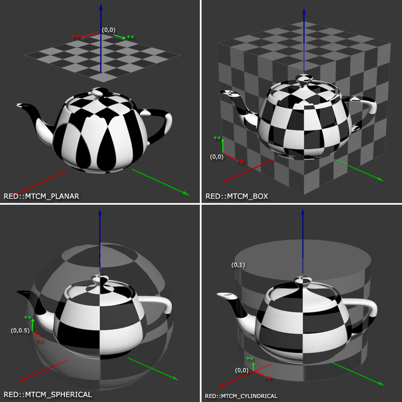
Each mapping primitive used in the process can be transformed with the ‘iTransform’ matrix parameter. Using a transform allows to scale, translate and rotate the primitive and change the output texture coordinates.
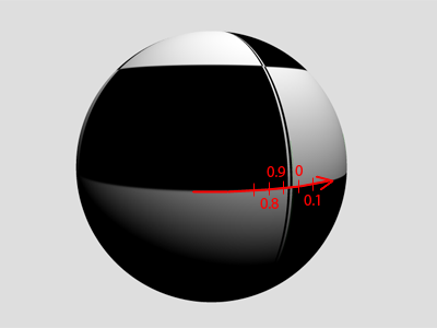
Note that the method does not modify the object topology. Therefore, depending on the chosen texture coordinate mode for the generation of the UV channel, texture wrappings may appear at the frontiers of the image. This is mostly true for the RED::MTCM_SPHERICAL, RED::MTCM_CYLINDRICAL and RED::MTCM_BOX
mappings.
Let’s take for exemple the following illustration. The U texture coordinate goes from 0.9 to 0 at the sphere seam so the entire texture is applied between the first and last vertices.
Parameters: - iTargetChannel – Channel that receive the texture coordinates.
- iTextureMapping – Texture coordinates mapping type.
- iTransform – Matrix used for texcoord transformations.
- iState – Current transaction.
Returns: RED_OK when the texture coordinates could have been calculated,
RED_BAD_PARAM if the method has received an invalid parameter,
RED_WORKFLOW_ERROR if the object does not have valid normals for the calculation,
RED_FAIL if the used channels are not of the appropriate format.
-
virtual RED_RC
BuildEdges(RED::Object *oEdgeShape, RED::MESH_CHANNEL iTargetVertexChannel, RED::MESH_CHANNEL iSourceVertexChannel, const RED::State &iState) const = 0 Constructs edges of a mesh.
Given a valid RED::ILineShape supplied as ‘oEdgeShape’, this routine analyzes the triangles of ‘this’ to construct the filtered list of edges that exist in the mesh.
The built edges list is not associated to the source triangles it’s originated from. The list of vertices in the mesh is duplicated in ‘oEdgeShape’.
See a practical example in the \ref wf_adding_edges tutorial.
Parameters: - oEdgeShape – a valid RED::ILineShape instance, that receives the edge list and vertices in ‘this’.
- iTargetVertexChannel – Channel in which vertices are stored.
- iSourceVertexChannel – Channel from which vertices are extracted.
- iState – Current transaction.
Returns: RED_OK when the operation has succeeded,
RED_BAD_PARAM if the method received an invalid parameter,
RED_ALLOC_FAILURE if an internal allocation has failed,
RED_FAIL otherwise.
-
virtual RED_RC
BuildContourEdges(RED::Object *oEdgeShape, RED::MESH_CHANNEL iTargetVertexChannel, RED::MESH_CHANNEL iTargetN1Channel, RED::MESH_CHANNEL iTargetN2Channel, RED::MESH_CHANNEL iSourceVertexChannel, const RED::State &iState) const = 0 Constructs edges of a mesh with contour extraction data.
This method works as RED::IMeshShape::BuildEdges except that it adds contour extraction information to the built list of edges. This contour information is basically made of normals of triangles that are using the edge.
An edge may be used by one, two or more triangles of the mesh. The method extracts at most two normals of two triangles that are sharing the edge.
Zero length normals are stored for frontier edges and for edges shared by more than two triangles.
Edges built by this method can be rendered by the RED::RenderShaderEdges.
See a practical example in the \ref wf_adding_edges tutorial.
Parameters: - oEdgeShape – a valid RED::ILineShape instance, that receives all edge parameters.
- iTargetVertexChannel – Target channel for vertex storage.
- iTargetN1Channel – Target channel for first normal data.
- iTargetN2Channel – Target channel for second normal data.
- iSourceVertexChannel – Channel from which vertices are extracted. Vertices must have 3 floating point coordinates.
- iState – Current transaction.
Returns: RED_OK when the operation has succeeded,
RED_BAD_PARAM if the method received an invalid parameter,
RED_ALLOC_FAILURE if an internal allocation has failed,
RED_FAIL if the source format is not matching the method requirements.
-
virtual RED_RC
BuildBorderEdges(RED::Object *oEdgeShape, RED::MESH_CHANNEL iTargetVertexChannel, RED::MESH_CHANNEL iSourceVertexChannel, const RED::State &iState) const = 0 Constructs border edges of a mesh.
Given a valid RED::ILineShape supplied as ‘oEdgeShape’, this routine analyzes the triangles of ‘this’ to construct the filtered list of border edges that exist in the mesh.
A border edge belongs to a single triangle in the mesh. The list of vertices in the mesh is duplicated in ‘oEdgeShape’.
See a practical example in the \ref wf_adding_edges tutorial.
Parameters: - oEdgeShape – a valid RED::ILineShape instance, that receives the edge list and vertices in ‘this’.
- iTargetVertexChannel – Channel in which vertices are stored.
- iSourceVertexChannel – Channel from which vertices are extracted.
- iState – Current transaction.
Returns: RED_OK when the operation has succeeded,
RED_BAD_PARAM if the method received an invalid parameter,
RED_ALLOC_FAILURE if an internal allocation has failed,
RED_FAIL otherwise.
-
virtual RED_RC
Shade(RED::MESH_CHANNEL iDestNormalChannel, RED::MESH_FORMAT iDestNormalFormat, RED::MESH_CHANNEL iSourceVertexChannel, const RED::State &iState) = 0 Edits or creates object normals.
This method define smooth normals for the object using the connectivity link that exist in the mesh. Each vertex receives a normal equal to the average normal of all triangles that are sharing it. Consequently this method smoothes all normals for all connected sets of vertices. Isolated faces in a mesh remain shaded separately.
If an array exists in ‘iDestNormalChannel’ then it’s overwritten and replaced by an array using 3 xyz normal coordinates stored using the ‘iDestNormalFormat’ format.
If a geometry has no triangles, any existing array in ‘iDestNormalChannel’ is left unmodified. If there’s no array in ‘iDestNormalChannel’, a normal array is created according to ‘iDestNormalFormat’ and filled with zero normals.
Parameters: - iDestNormalChannel – Geometry channel that receive created normals.
- iDestNormalFormat – Format of the created normal array.
- iSourceVertexChannel – Source vertices in the mesh.
- iState – Current transaction.
Returns: RED_OK if the operation has succeeded,
RED_BAD_PARAM if the method has received an invalid parameter,
RED_ALLOC_FAILURE if an internal allocation has failed,
RED_FAIL if a normal array format problem has occurred, or if an unexpected error has occurred.
-
virtual RED_RC
ShadeTJunction(RED::MESH_CHANNEL iDestNormalChannel, RED::MESH_FORMAT iDestNormalFormat, RED::MESH_CHANNEL iSourceVertexChannel, int iLookupDepth, const RED::State &iState) = 0 Edits or creates object normals with T junction cracks.
This method behaves similarly to the RED::IMeshShape::Shade method, except that it takes into consideration T junction cracks in the shading at each vertex.
a T junction crack occurs at a vertex that is lying on an edge of a neighboring triangle, forming a ‘T’ shape if we look at the geometry edges.
Normal interpolation of T junction cracks is wrong because a standard smooth shading method will consider all triangles that share a given vertex in the shading equation, without taking into consideration other triangles that do not share the vertex at one of their extremities, but along one of their edges.
The method analyzes vertices at T junction and look for neighbors at the specified ‘iDepth’. Usually a depth of 1 or 2 is enough.
If an array exists in ‘iDestNormalChannel’ then it’s overwritten and replaced by an array using 3 xyz normal coordinates stored using the ‘iDestNormalFormat’ format.
If a geometry has no triangles, any existing array in ‘iDestNormalChannel’ is left unmodified. If there’s no array in ‘iDestNormalChannel’, a normal array is created according to ‘iDestNormalFormat’ and filled with zero normals.
The method does nothing if the mesh stores triangles with adjacency informations.
Parameters: - iDestNormalChannel – Geometry channel that receive the created normals.
- iDestNormalFormat – Format of the created normal array.
- iSourceVertexChannel – Source vertices in the mesh.
- iLookupDepth – Neighboring distance used in the T junction search. This value must in [ 1, 5 ].
- iState – Current transaction.
Returns: RED_OK if the operation has succeeded,
RED_BAD_PARAM if the method has received an invalid parameter,
RED_ALLOC_FAILURE if an internal allocation has failed,
RED_FAIL if a normal array format problem has occurred, or if an unexpected error has occurred.
-
virtual RED_RC
Collapse(double iDistanceTolerance, double iAngleTolerance, const RED::State &iState, const RED::Vector<RED::MESH_CHANNEL> *iDistanceToleranceChannels = NULL, const RED::Vector<RED::MESH_CHANNEL> *iAngleToleranceChannels = NULL) = 0 Removes duplicate vertices.
This method removes all duplicates vertices in the mesh and changes all triangles indices accordingly. Two vertices are considered identical if all the channels that are declared to be checked have identical values for the provided tolerancies.
The method offers two kinds of comparisons for two values in a vertex mesh channel:
- Axis distance tolerancy: maximal distance between two vertices along each x,y,z,w axis.
- Angular tolerancy: maximal angle in radians between two identical directions.
By default, if the two supplied lists of channels are NULL, the method will check all data channels in a mesh, using the following tolerancies:
- Angular tolerancy is used for RED::MCL_NORMAL and RED::MCL_USER0.
- Axis distance tolerancy is used for all other mesh channels.
Then, if a channel is not found in the two provided lists of channels, it’s ignored and during the vertex merge operation, any of the two values for this channel that exist will be used for the merged vertex.
All degenerated triangles resulting of collapsed geometries are removed.
Note that the method can’t operate on meshes with shared arrays as it needs to reallocate memory to eliminate redundancies. Similarly, the method has no effect on meshes that have adjacency elements.
See also \ref wf_generating_vector_graphics.
Parameters: - iDistanceTolerance – Numerical tolerancy used for all channels to compare in distance. This value must be greater than or equal to zero.
- iAngleTolerance – Maximal angle (in radians) that can exist between two identical normals. This value must be in [ 0.0, RED_PI ].
- iState – Current transaction.
- iDistanceToleranceChannels – List of channels to compare using the distance tolerance.
- iAngleToleranceChannels – List of channels to compare using the angular tolerance.
Returns: RED_OK if the operation has succeeded,
RED_BAD_PARAM if the method has received an invalid parameter,
RED_BAD_PARAM if the same channel is in the two lists of channels,
RED_ALLOC_FAILURE if an internal allocation has failed,
RED_FAIL if an unexpected error has occurred,
RED_FAIL if the mesh has shared arrays.
-
virtual RED_RC
BuildCutMesh(RED::Object *ioCutMesh, const RED::Vector<RED::Object*> &ioCutSection, const RED::Vector<RED::Object*> &ioCutContour, const RED::Vector<double> &iPlane, double iTolerance, const RED::State &iState) const = 0 Cut a mesh using a list of specified cutting planes.
This method can be used to cut a mesh by any number of cutting planes specified in iCuttingPlanes. The method does not actually modify the contents of this. It fills ioCutMesh, ioCutSection meshes and ioCutContour lines that have been sent to the method. Vertex coordinates are assumed to be in RED::MCL_VERTEX, normals in RED::MCL_NORMAL.
This is a software cut operation performed on mesh triangles that differ a lot from the RED::IMaterial::SetCuttingPlane method which is a GPU based real-time operation, as illustrated in the \ref wf_section_cutting tutorial.
It’s the responsibility of the caller to create ioCutMesh, ioCutSection and ioCutContour before the call and to release them after use. Please note that using ioCutSection and ioCutContour are optional and can be empty vectors or both must have a number of entries equal to the number of planes involved in the cut operation. ioCutMesh and ioCutSection must contain CID_REDMeshShape. ioCutContour must contain CID_REDLineShape objects.
The resulting cut contours are parametrized line shapes (see RED::ILineShape::Parametrize), and should be rendered with a parametrization material (RED::IResourceManager::CreateParametrizationMaterial).
The resulting section shapes have vertices and normal attributes set. Vertex normals are set as the corresponding cut plane normal to ensure a proper shading.
The source mesh (this) must have a correct topology for the operation to work. It must be a closed non manifold solid shape. This means that each edge in the source mesh must be exactly shared twice by triangles that define the mesh (without considering duplicate vertices that result of shading). So a source mesh that is closed but that has duplicate vertices for shading purposes is correct. For instance a cube has 24 vertices at 8 real positions in space, each vertex being duplicated three times to store per face normals that are requested for shading. After a collapse operation, this cube has only 8 vertices and is a closed solid whose topology is suitable for the operation.
The source mesh (this) should not have any adjacency information stored, otherwise, the method will return RED_WORKFLOW_ERROR.
Parameters: - ioCutMesh – Resulting mesh containing the sliced triangles after the cut operation. Must be set to a valid mesh shape address.
- ioCutSection – Resulting meshes containing the polygonal sliced sections. One mesh shape needs to be supplied for each input plane. The number of cut contours must be equal to the number of cut sections.
- ioCutContour – Resulting contours resulting of the cut operation. One line shape needs to be supplied for each input plane. The number of cut contours must be equal to the number of cut sections.
- iPlane – List of plane equations that cut this. The positive side of the plane is discarded (e.g if we have a plane with normal equal to +z, we keep the negative z part of the mesh). Each plane is specified by its equation (4 doubles A, B, C, D for A*x + B*y + C*z + D = 0).
- iTolerance – Numerical tolerancy used to collapse the source mesh internally to get it as a plain closed solid. If the tolerancy is too small, the collapse operation may fail to turn this as a plain solid, resulting in erroneous output of the method.
- iState – Current transaction.
Returns: RED_OK if the operation has succeeded,
RED_BAD_PARAM if the method has received an invalid parameter,
RED_BAD_PARAM if iPlane doesn’t have 4 values per plane,
RED_BAD_PARAM if we have inconsistent lists in ioCutSection and ioCutContour,
RED_ALLOC_FAILURE if an internal allocation has failed,
RED_WORKFLOW_ERROR if this stores triangle adjacency,
RED_FAIL if an unexpected error has occurred.
-
virtual RED_RC
SortPolygons(const RED::Vector3 &iDirection, int iTrianglesCount, const RED::State &iState) = 0 Performs a distance sorting of polygons in a mesh.
This method will process all the triangles of the mesh, by packs of ‘iTrianglesCount’ triangles and it’ll reorder the index array of the mesh so that polygons are sorted back to front in distance along the specified ‘iDirection’.
If ‘iTrianglesCount’ is equal to 1, then all triangles are separatedly sorted. If ‘iTrianglesCount’ is equal to 2, then the method sorts groups of 2 triangles (generally quads). Larger groups of triangles can be sorted too.
Parameters: - iDirection – Depth sorting axis.
- iTrianglesCount – Number of triangles to group for each sorted entity.
- iState – Current transaction.
Returns: RED_OK if the operation has succeeded,
RED_BAD_PARAM if iTrianglesCount is lower than 1,
RED_WORKFLOW_ERROR if the shape contains lines or points instead of triangles,
RED_WORKFLOW_ERROR if the shape has triangles with adjacency informations,
RED_ALLOC_FAILURE if an internal allocation has failed,
RED_FAIL if the number of triangles in the shape is not an exact multiple of iTrianglesCount,
RED_FAIL if an unexpected error has occurred.
-
virtual RED_RC
BuildTrianglesAdjacency(const RED::State &iState) = 0 Constructs triangle adjacency for the current object.
This method takes the current list of triangles in this and replaces it with a list of triangles that contain adjacency informations, as a call to RED::IMeshShape::AddTrianglesAdjacency would do.
If the object already has adjacency informations, the method does nothing.
The method does not work on shared lists of triangles.
The method does not work on manifold topologies.The opposite operation is performed by RED::IMeshShape::RemoveTrianglesAdjacency.
Parameters: iState – Current transaction. Returns: RED_OK if the operation has succeeded, RED_WORKFLOW_ERROR if the shape has a shared list of triangles,
RED_ALLOC_FAILURE if an internal allocation has failed,
RED_FAIL if the source mesh is a manifold topology,
RED_FAIL if an unexpected error has occurred.
-
virtual RED_RC
RemoveTrianglesAdjacency(const RED::State &iState) = 0 Removes triangle adjacency from the current object.
This method does the opposite of RED::IMeshShape::BuildTrianglesAdjacency: it removes all adjacency information from the shape and replaces its list of triangles with adjacency by a list of triangles with no adjacency informations.
If the shape has no adjacency informations, the method does nothing. The method does not work on shared lists of triangles.
Parameters: iState – Current transaction. Returns: RED_OK if the operation has succeeded, RED_WORKFLOW_ERROR if the shape has a shared list of triangles,
RED_ALLOC_FAILURE if an internal allocation has failed,
RED_FAIL if an unexpected error has occurred.
-
virtual RED_RC
CopyFrom(const RED::Object &iMesh, const RED::State &iState, int iSrcStateNumber = -1) = 0 Copies the content of a RED::IMeshShape instance to the current object.
This method will work for only two instances of the same concrete class.
Parameters: - iMesh – Reference to the object to copy from.
- iState – Current transaction.
- iSrcStateNumber – State from which the source mesh must be copied.
Returns: RED_OK on success,
RED_BAD_PARAM if ‘iMesh’ and ‘this’ are from different classes, or if ‘iSrcStateNumber’ is invalid,
RED_ALLOC_FAILURE if an internal allocation has failed,
RED_FAIL for any other error.
-

