Deferred Shading Using Multiple Render Targets
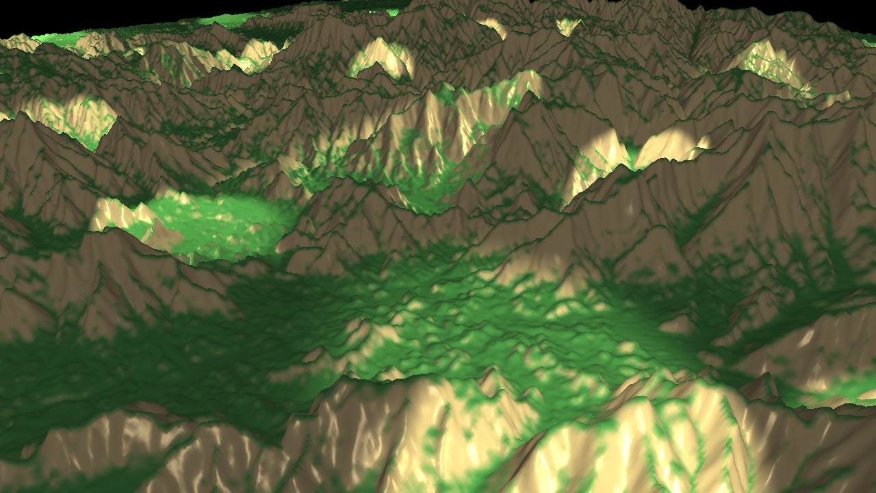
This tutorial describes how to use multiple render targets to do deferred shading with HOOPS Luminate. To demonstrate the advantages of deferred shading versus classical forward shading, the scene is composed of a huge mesh (4 millions vertices) and several lights (ambient, point and spot lights). In a first step of the tutorial, the scene is rendered in forward shading using the HOOPS Luminate generic material. The second step uses our custom deferred shaders.
The huge mesh rendered with HOOPS Luminate generic material
What is Deferred Shading?
Deferred shading is a screen space shading technique done in two passes. In a first pass called geometry pass, data required for shading computation are rendered as a series of textures in a geometry buffer (G-buffer). The second pass calculates the lighting at each pixel during the pixel shader stage using the G-buffer data.
The principle advantage of this technique is to decouple the scene geometry from the lighting. Each light is rendered using only one simple geometry, and is only computed for the pixels that it affects. It allows to add several lights sources in the scene without a significant performance-hit.
With the usual forward shading approach, the shading is done like this:
for each light
{
  for each object
  {
    render object to the framebuffer
  }
}
With the deferred shading approach, the shading is done like this:
for each object
{
  render object to the g-buffer
}
for each light
{
  render light geometry using the g-buffer to perform lighting
}
The cost of forward shading is N*M while the cost of deferred is N+M. Because lighting is done in screen space, the cost of lighting is proportional to the area covered by the light.
The main disadvantages are:
- Difficulty to handle different shading models
- Inability to handle transparency correctly
- Inability to do hardware anti-aliasing
Geometry Pass using Multiple Render Targets
The first pass is the geometry pass. The goal of this pass is to render the G-buffer. This technique uses multiple render targets. HOOPS Luminate allows to create a special RED::IViewpointRenderList handling multiple render targets with the following function: RED::IWindow::CreateMultiRenderTargetVRL.
// Create an auxiliary VRL with 4 render targets to render the G-Buffer:
RED::FORMAT fmt_list[ 4 ] = { RED::FMT_HALF_FLOAT_RGB, RED::FMT_HALF_FLOAT_RGB, RED::FMT_HALF_FLOAT_RGB, RED::FMT_HALF_FLOAT_RGB };
RC_TEST( iwindow->CreateMultiRenderTargetVRL( g_geom_vrl, width, height, fmt_list, 4, true, iresmgr->GetState() ) );
RED::IViewpointRenderList* ivrl_geom = g_geom_vrl->As< RED::IViewpointRenderList >();
Here a VRL handling 4 render targets is created. These 4 textures are the geometry buffer and will contain:
- Diffuse Color
- Position
- Normal
- Texture Coordinates
A custom material is created for the mesh. It contains custom vertex and pixel shaders programs written is GLSL. These shaders are added to the RED::MTL_PRELIT pass.
The vertex shader only transfers the data from the geometry to the pixel shader (position, normal, texture coordinates and color):
// Write the transformed position:
gl_Position = gl_ModelViewProjectionMatrix * gl_Vertex;

// Transfer the position in world space:
vec4 pos = gl_TextureMatrix[1] * gl_Vertex;
vertex_out.vPosition = pos.xyz;

// Transfer the normal in world space:
vec4 nor = gl_TextureMatrixInverseTranspose[1] * vec4( gl_Normal.xyz, 1.0 );
vertex_out.vNormal = nor.xyz;

// Transfer the texture coordinates:
vertex_out.vTexCoord = gl_MultiTexCoord0.xy;

// Transfer the color:
vertex_out.vColor = gl_Color;
The pixel shader simply writes the data in the 4 textures of the G-buffer:
// Write the data in the 4 render targets: diffuse, position, normal, texture coordinates:
gl_FragData[0] = vec4( vertex_in.vColor );
gl_FragData[1] = vec4( vertex_in.vPosition.xyz, 0 );
gl_FragData[2] = vec4( vertex_in.vNormal.xyz, 0 );
gl_FragData[3] = vec4( vertex_in.vTexCoord.xy, 0, 0 );
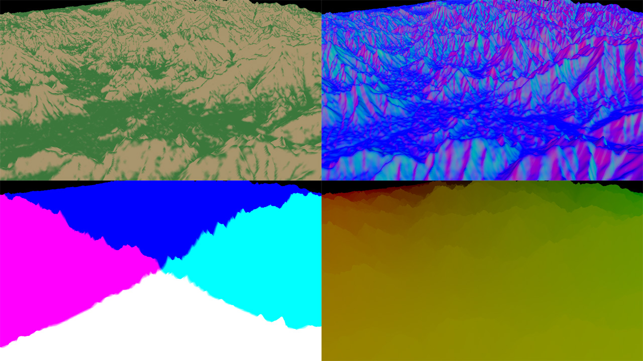
The G-Buffer is composed of diffuse, normal, position and texture coordinates
Lighting Pass
The second pass of the deferred shading is the lighting one. Here, all the scene lights are rendered using geometry primitives. Thus only the pixels affected by the light geometry will be drawn.
In the tutorial, a second RED::IViewpoint is created to handle the light geometries. For each light, a corresponding geometry is created and added to the camera scene graph and a custom material is applied to it. By doing this, no lighting pass (RED::MTL_LIT) is required, only a single RED::MTL_PRELIT pass will be used to render all the light geometries.
A custom blending mode must be used to add the light contributions. This is done via a RED::StateShader.
// Create a state shader:
//  o Cull the back face.
//  o Don't do depth test as all the lights need to be used.
//  o Custom blending mode: Additive
RED::StateShader statesh;
RC_TEST( statesh.SetFaceCulling( RED::StateShader::BACK ) );
RC_TEST( statesh.SetDepthTest( RED::StateShader::OFF ) );
RC_TEST( statesh.SetBlendingMode( RED::StateShader::CUSTOM,
                                  RED::StateShader::ONE,
                                  RED::StateShader::ADD,
                                  RED::StateShader::ONE ) );

RC_TEST( imat->RegisterShader( statesh, iresmgr->GetState() ) );
RC_TEST( imat->AddShaderToPass( statesh.GetID(), RED::MTL_PRELIT, RED::LIST_LAST, RED::LayerSet::ALL_LAYERS, iresmgr->GetState() ) );
The vertex shader program is the same for all the lights. It only transforms the vertices from object to clip space:
void main(void)
{
  // Write the transformed position:
  gl_Position = gl_ModelViewProjectionMatrix * gl_Vertex;
}
The previously computed G-buffer textures are also transmitted to the lighting material via pixel shader parameters:
// Transfer the G-buffer to the lighting shader:
RED::IViewpointRenderList* ivrl = iVRL->As< RED::IViewpointRenderList >();

RED::RenderShaderParameter param_diffuseTexture( "diffuseTexture", 0, RED::RenderShaderParameter::PSH );
param_diffuseTexture.SetImage( ivrl->GetRenderImage(0) );
RC_TEST( deferred.AddParameter( param_diffuseTexture, RED_L0 ) );

RED::RenderShaderParameter param_positionTexture( "positionTexture", 1, RED::RenderShaderParameter::PSH );
param_positionTexture.SetImage( ivrl->GetRenderImage(1) );
RC_TEST( deferred.AddParameter( param_positionTexture, RED_L0 ) );

RED::RenderShaderParameter param_normalTexture( "normalTexture", 2, RED::RenderShaderParameter::PSH );
param_normalTexture.SetImage( ivrl->GetRenderImage(2) );
RC_TEST( deferred.AddParameter( param_normalTexture, RED_L0 ) );
Ambient Light
The ambient light affects all the pixels of the screen, a fullscreen quad is created (see RED::IMeshShape::Quad) with a custom material.
The pixel shader computes the ambient lighting using the position texture of the G-buffer:
void main(void)
{
  // Ambient lighting:
  vec4 texDiffuse = texture2DRect( diffuseTexture, vec2( gl_FragCoord ) );

  gl_FragColor = texDiffuse * lightColor;
  gl_FragColor.a = 1.0;
}
Spot Light
All the spot lights of the scene can be drawn as cone geometries (see RED::IMeshShape::Cone). Thus, only the pixels inside the cone shape will be calculated.
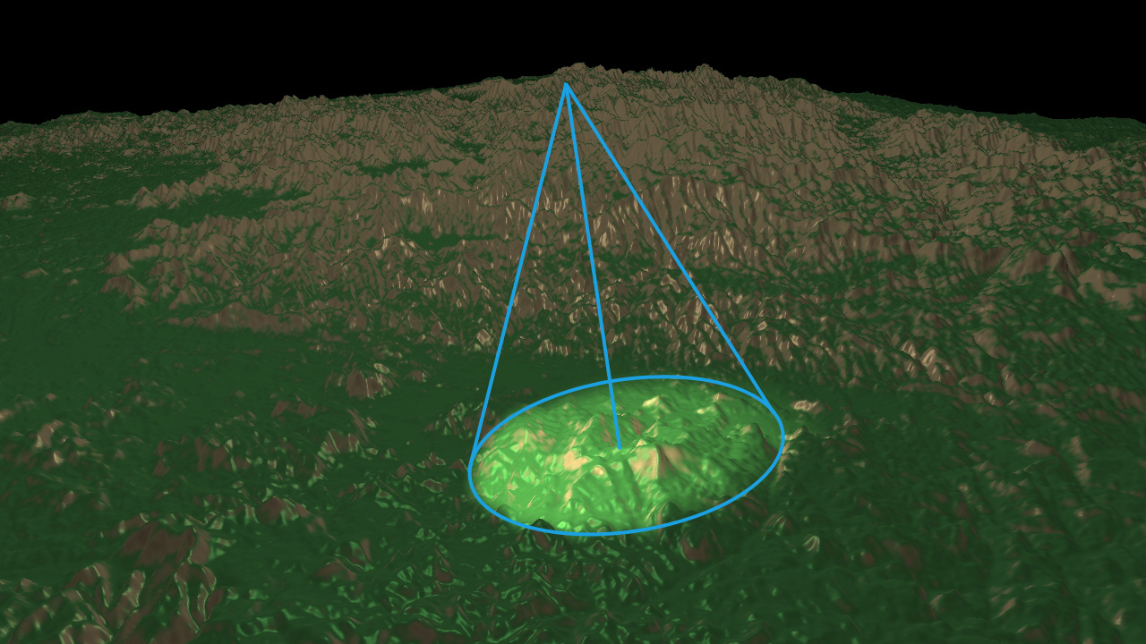
A spot light is drawn as a cone
The pixel shader written in the tutorial is a basic phong shader. The only difference is that it uses the G-buffer instead of the transformed geometries.
void main(void)
{
  // Get the G-buffer data:
  vec4 texDiffuse = texture2DRect( diffuseTexture, vec2( gl_FragCoord ) );
  vec4 texPosition = texture2DRect( positionTexture, vec2( gl_FragCoord ) );
  vec4 texNormal = texture2DRect( normalTexture, vec2( gl_FragCoord ) );

  // Phong lighting:
  vec3 light   = normalize( lightPos.xyz - texPosition.xyz );
  vec3 normal  = normalize( texNormal.xyz );
  vec3 eye     = normalize( eyePos.xyz - texPosition.xyz );
  vec3 reflect = 2.0 * clamp( dot( normal, light ), 0.0, 1.0 ) * normal - light;

  float diffuse = clamp( dot( light, normal ), 0.0, 1.0 );
  float specular = pow( clamp( dot( reflect, eye ), 0.0, 1.0 ), 60.0 );
  float falloff = smoothstep( cos( lightAngle + lightFalloff ), cos( lightAngle ), dot( -light, lightDir ) );

  gl_FragColor = texDiffuse * lightColor * ( diffuse + specular ) * falloff;
  gl_FragColor.a = 1.0;
}
Note
All the light parameters (spot angle, diffuse color, position, etc.) are transmitted via pixel shader parameters.
Point Light
The point lights are rendered using sphere meshes (see RED::IMeshShape::Sphere). The pixel shader is the same as the spot light one with a spot angle of pi.