Matrix Transforms in a Cluster
Each object in the HOOPS Luminate cluster defines a transformation matrix in the rendering pipeline. The schema below illustrates all the transformation flow that exist inside HOOPS Luminate and the API calls that can be used to access each transform:
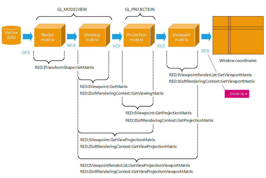
The data flow from model coordinates to screen coordinates
The schema starts from the left side with the input vertex data in Object Coordinate System (OCS). Successive transformation matrix are applied to the input data:
- The model transform matrix. This the cumulated transformation matrix from the root of the scene graph down to the object instance that is applied first and that transforms the vertex data from the OCS to the World Coordinate System (WCS). The
RED::ITransformShape::SetMatrixand corresponding Get methods can be used to define matrix transforms in the scene graph. The HOOPS Luminate Scene Graph Overview chapter provides details on the transformation inheritance rules that are used in a HOOPS Luminate scene graph. - The camera viewing matrix transformation is applied next. It can be accessed from the
RED::IViewpoint::GetViewingMatrixmethod or from theRED::ISoftRenderingContext::GetViewingMatrixmethod for a software shader during a software image calculation. After the application of this matrix, data is in the View Coordinate System (VCS). The combination of these two matrices is equivalent to theGL_MODELVIEWmatrix that can be queried from OpenGL. - The third transformation to be applied is the projection matrix. The projection matrix transforms data in VCS into data in Device Coordinate System (DCS). Coordinates have not been clip divided at this stage, hence this is a homogeneous coordinate system. This transform is the GL_PROJECTION matrix transform being set in OpenGL. It can be accessed from the
RED::IViewpoint::GetProjectionMatrixand the equivalent software call:RED::ISoftRenderingContext::GetProjectionMatrix. - The final transform is defined by the viewporting area of the camera inside its VRL. This is the
RED::IViewpointRenderList::InsertViewpointcall that defines this matrix. Note that the coordinates returned are defined from the viewpoint’s anchor inside the VRL. So, the (0,0) screen coordinate defined by this transform is located at the viewpoint’s anchor that was used while inserting the camera inside the window. Access to the viewport matrix can occur from theRED::IViewpointRenderList::GetViewportMatrixand from the equivalent software class:RED::ISoftRenderingContext::GetViewportMatrix.
So for example, the complete matrix transform (except the model matrix in the example below) can be used to convert a pick line from DCS to WCS back and forth using the following code:
// 'ivrl' is our RED::IViewpointRenderList interface, and we're working on our viewpoint identified by 'camera':
RED::Matrix vpvinv;
RC_TEST( ivrl->GetViewProjectionViewportMatrix( vpvinv, camera ) );
RC_TEST( vpvinv.Invert() );

// Our pick line ( A, B ) starts from ( x, y, 0 ) and ends at ( x, y, 1 ), where the z coordinate
// is the depth. In device coordinates a point at z = 0.0 is on the camera near clipping plane and
// a point at z = 1.0 is on the camera far clipping plane.
double tmp[4], dcs[4];
double A[3], B[3];

dcs[0] = 0.5 + x;      // (x,y) are screen coordinates
dcs[1] = 0.5 + y;      // (x,y) are screen coordinates
dcs[2] = 0.0;          // point is at z = dnear.
dcs[3] = 1.0;
vpvinv.Multiply4( tmp, dcs );
A[0] = tmp[0] / tmp[3];
A[1] = tmp[1] / tmp[3];
A[2] = tmp[2] / tmp[3];

dcs[2] = 1.0;          // second pick line point is at z = dfar.

vpvinv.Multiply4( tmp, dcs );
B[0] = tmp[0] / tmp[3];
B[1] = tmp[1] / tmp[3];
B[2] = tmp[2] / tmp[3];