Hardware Display Performances
There are several levers for anyone using HOOPS Luminate that can be activated to optimize hardware display performances. The purpose of this page is to review them. So we only discuss GPU specific stuff here.
A Word on Hardware Rendering Orders
HOOPS Luminate internally uses a primitive batching system to reduce the amount of orders that need to be sent to the GPU. Basically, this system aims at classifying objects by the material they use in the end - that is after resolution of the scene graph inheritance rules - as illustrated below:
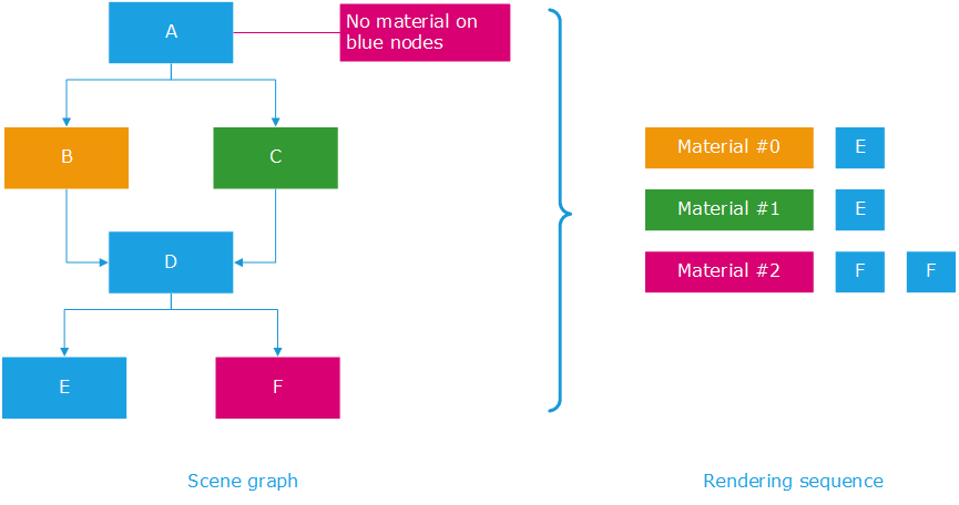
The hardware rendering sequence using the per material classification
If we consider the small scene graph in the illustration above, we see that it displays 4 geometries: E is rendered twice, F is rendered twice too as we have two instances of each. If we apply material inheritance rules (Shape Attributes in a Scene Graph) to that scene graph, then the orange material renders E once, the green material renders E once and the purple material renders F twice.
HOOPS Luminate will do that exactly in that order: it’ll classify primitives by materials that need to be setup for their rendering by the GPU. This way it’ll reduce the number of times it has to change the setup of the GPU for the rendering. If it were to render the scene using a “natural order”, then the rendering sequence would be larger: Setup the orange material, render E, setup the purple material, render F, setup the green material, render E, setup the purple material, render F: so one setup would be wasted in the operation.
So as a consequence, we can get our first lever on improving hardware rendering performances:
Reducing the Number of Materials
The first quick win here is about using as little materials as possible to render a given scene. Using fewer materials will increase the overall rendering performance of the application.
Ok, but you may think that you can’t do anything about that: If you have created materials that’s because you needed them. Sure, but some alternatives can still be considered to reduce the number of materials in your application:
- If two materials only differ by a color, then use only one of them and specify the color from the geometry directly. Two mechanisms can be used here to achieve that: Instances or simply add colors as vertex colors in geometry channels. The extra cost of adding a color to geometry vertices is generally balanced by the saved performance.
- If two materials only differ by textures, then you may consider merging your texture together in larger texture atlases. Using a single large atlas is a common task that reduce the number of times a the GPU setup needs to be modified in the rendering pipeline.
A Word on Primitive Batching
The rendering of all objects that are using a given materials is also something which is optimized by HOOPS Luminate: if we have a scene with thousands of small objects that are all rendered using the same material, HOOPS Luminate will avoid rendering each of them separately:
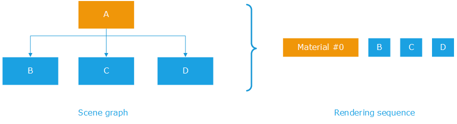
Hardware batching per material in HOOPS Luminate
In the simple example above, we have three objects: B, C and D that are all rendered with the material set on A. HOOPS Luminate groups B, C and D’s geometries and render all three objects in one single rendering call. Then, if we have intermediate transformation nodes used to reposition geometries, then the rendering sequence may be interrupted:
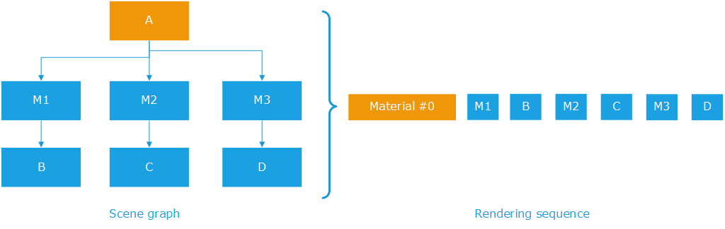
Hardware batching per material, with matrices
The scene graph has three matrices, so unlike in the previous example, HOOPS Luminate can no longer group the rendering commands for B, C and D into one single rendering call. It needs to setup M1 before rendering B; M2 before rendering C and M3 before rendering D.
So our second lever is here:
Reducing the Number of Transformation Matrices
As for materials, this can be something not easy to do. All objects that are rendered with the same material with the same transformation will be clustered together by HOOPS Luminate so that one single rendering call submitted to the GPU can render all of them at once. However,
- Using extra nodes to position small objects may be more costly than directly position the objects themselves.
- Instancing small objects may not save any memory and cost rendering time: The cost of creating a node and a hierarchy of shapes should be lower than simply duplicating the underlying geometry. Therefore instancing objects is not worth the effort if the object has only a few triangles or lines, as this is often the case in the 2D world.
So this is a more general design rule here: please carefully select the scene graph organization that aims at having a scene graph as simple as possible. Specifically, disconnecting the application semantics from the scene graph organization may be a must have to get a speed boost during the draw. We illustrate this for the specific 2D case here: Rendering 2D Datasets.
Reducing the Number of Rendering Passes
Increasing performances is all about starting a diet therapy…After having reduced the number of materials, the number of transformation matrices, let’s reduce the number of rendering passes too!
The number of rendering passes in HOOPS Luminate is directly related to the setup of the engine in terms of options, materials and lighting. The total number of rendering passes involved in processing a scene can be estimated using details provided here: Real-Time Rendering of 3D Datasets. Each time the number of rendering passes is increased, the rendering time will get higher: for each rendering pass, the engine needs to determine the set of objects to be rendered, it needs to setup the necessary materials and proceed with the rendering. So using too many passes can be counter productive here.
That being said, some applications that need to be flexible on lighting and on advanced rendering effects will not have the freedom to reduce their number of rendering passes. However, performance critical applications can generally go for materials using one unique shader for all their renderings. This can reduce significantly the number of times the geometry gets drawn on screen.
Reducing the Effect Area of Lights
All lights in HOOPS Luminate do have an effect range. The effect of the RED::OPTIONS_LIGHT_CUTOFF is detailed for optimization of software display performances here Software Display Performances, but this also applies to hardware rendering: Reducing the effect range of a light will reduce the number of geometries influenced by that light and therefore display performance will vary in accordance with the workload of objects to process for each light.
Reducing the Rendering Workload using Culling Callbacks
Culling callbacks can be used for several purposes. One of them is about using Levels Of Detail (LODs). We review LOD usage here: Levels Of Detail, that can significantly reduce the number of triangles to be displayed. However with modern graphic hardware that are really good at crunching billions of triangles every frame, one must be cautious about using LODs as the time taken to select a given LOD can be greater than the time that would be taken by rendering the full geometry. All the efficiency on LODs greatly vary with the type and purpose of the application we consider here.
Besides using LODs, culling callbacks and Culling Methods available in HOOPS Luminate can be a good lever to activate to reduce the rendering workload.
Using Single Side Geometries
While this has definitely no importance in software rendering, the fact of rendering single sided or dual sided polygons using graphics hardware will change the application performances a lot: double sided polygons double the fill rate consumed by the rendering, or may even provoke another rendering pass to occur (if built-in shaders are used for instance).
Note that on most graphic hardware, using alpha masking (RED::StateShader::SetMaskedTransparency) or writing custom depth values into a shader program disable early z culling available on the graphics hardware: this means that the cost of the pixel shader will be paid whatever the visibility of the rendered triangle.
Using Short Indexed Geometries
This is a small optimization, that may be ignored on the newest hardware, but that used to work well with quite old GPUs: The specification of an index array in a RED::IMeshShape objects uses (int) sized values to indicate a vertex number. Internally, HOOPS Luminate will turn the array of indices into (short) values, that are smaller in memory and faster to access for the GPU memory. This can save a bit of performance and memory as well. This is automatic and effective only if the mesh shape uses less than 65536 vertices.
Customized Shadow Mapping
Shadow mapping may require a careful customization to produce good results, as detailed here: Shadow Mapping Detailed. Most important is the shadow map range. On most graphic hardware, the depth buffer used to calculate a shadow map uses 22 bits of mantissa, which is not enough to cover all ranges in all rendering configurations. Then, among the tools offered by HOOPS Luminate to customize shadow mapping, we find the auto-range feature that will automatically calculate good values for the near and far distances to use for the shadow map.
Of course, this algorithm, which is enabled by default, has a cost. Turning it off using RED::ILightShape::SetShadowMapCustomRange may help increase the rendering performances of the application.
Similarly, using the RED::ILightShape::SetShadowMapBlur may slow down the display or not. High end hardware with a strong shading power will not suffer of large shadow mapping blur values, however entry level GPUs don’t have the same capabilities and reducing the shadow map blur may significantly increase their rendering performance.
GLSL Shaders Startup Latency
GLSL is a high level shading language. Therefore a pair of GLSL programs (a vertex shader plus a pixel shader) needs to be compiled and linked before it can be executed by the GPU.
Compilation and link is performed by the graphic driver’s compiler. Several optimization phases are needed to convert the high level C-like language into hardware assembly with good performances. As a consequence, this process takes time (syntax analysis, parsing, etc…) The longer the shader, the longer the time needed to load and execute it.
This process is done once per pair of GLSL programs, but it takes some time, and it can cause some delay on the first usage of the shader.
ARB shaders do not suffer from this latency. Translation of an ARB program into hardware assembly level code is quite straightforward, as ARB shaders are only made of low level simple operations.

