Shader Debugging
CPU Shader Debugging
The software shaders are written in C++. Therefore, they can be debugged like any C++ program using your favorite Integrated Development Environment.
Note
The software shading functions are called in a multi-threaded context. Be careful to take that into account when debugging them.
GPU Shader Debugging
Besides prototyping debuggers, there’s no robust industrial debugging solution available to track GPU shader errors. This may change in the near future. In the mean-time, we propose some clues that may be helpful understanding why the result of a rendering is not as expected.
Checking the Rendered Geometry
This is the black screen problem. The simplest way to avoid the black screen is to set a non black background color in the viewpoint render list hosting the viewpoint. This will validate the presence of the geometry in the scene.
Getting away from a black screen
If we are certain that the geometry is rendered, we can move to the next step. If the geometry does not show up, then we should check the following:
Do the shaders compile?
If they do not compile, the RED engine will display an error panel before silently ignoring the rendered geometry. The engine always tries to display all what it is able to, therefore shapes owning a material with invalid shaders are not rendered. The first time a shader with a compilation error is being loaded, an error panel is displayed: The faulty program source code and the corresponding errors are dumped to disk in ‘shader_program.txt’ and ‘shader_error.txt’.
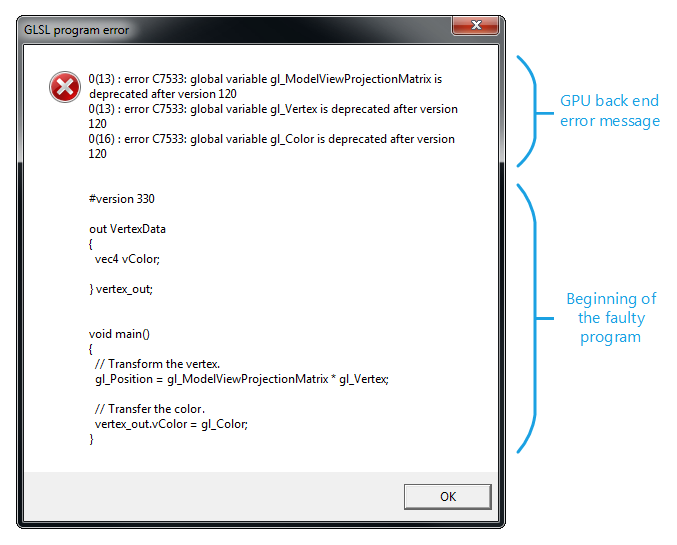
A GLSL shader compilation error panel
Note
The panel will show up during the rendering of the next frame after the shader has been loaded (e.g. shader loading is postponed until the shader is really needed for the rendering).
Is the RED::RenderCode binding correct?
Be sure that all drawn meshes have a valid vertex data channel and that this channel is used by the RED::RenderCode of the shader.
Checking the Shader Pipeline
Once we are sure that something is really rendered on screen, we must validate the vertex and pixel shader chain. For that the simplest is to set the pixel shader to a constant output color. We’ll use it at every step to validate our various shader inputs.
RED::ShaderString str;

// Pixel shader code.
str.PixelShaderStart();
str.Add( "MOV result.color, {1,1,1,1};\n" );
str.ShaderEnd();

We are sure that our pixel shader is really called
Note
This only validates our pixel shader. We are not sure that our vertex shader is really called. To be sure of that, we can use a simple pairs of programs as shown below:
// Vertex shader code:
str.VertexShaderStart();
str.VertexTransform( "result.position", "state.matrix.program[2]", "vertex.attrib[0]" );
str.Add( "MOV result.texcoord[0], {1,1,1,1};\n" );
str.ShaderEnd();

// Pixel shader code:
str.PixelShaderStart();
str.Add( "MOV result.color, fragment.texcoord[0];\n" );
str.ShaderEnd();
This validates our vertex and pixel shader sequence. With our shader pair being validated, we can start the checkup of all our input values, and all calculations that are made with them. In the example above, we have removed all vertex displacement resulting of the vertex shader. If there’s no error in the displacement, it could be let in place of the default model view matrix projection transformation.
Checking Vertex Shader Inputs
The simplest way to check a vertex shader input attribute is to transmit it to the pixel shader using an unused texture channel. Texture interpolators are not clamped between the vertex and the pixel shader. Color interpolators are clamped to the [0, 1] value range, and one should be aware of this. So, we can add the following code to transmit our raw input attribute to the pixel shader for a checkup:
// Vertex shader code:
str.VertexShaderStart();
str.Add("MOV result.texcoord[0], vertex.attrib[0];\n");
// ...
str.ShaderEnd();

// Pixel shader code:
str.PixelShaderStart();
str.Add("MOV result.color, fragment.texcoord[0];\n");
str.ShaderEnd();
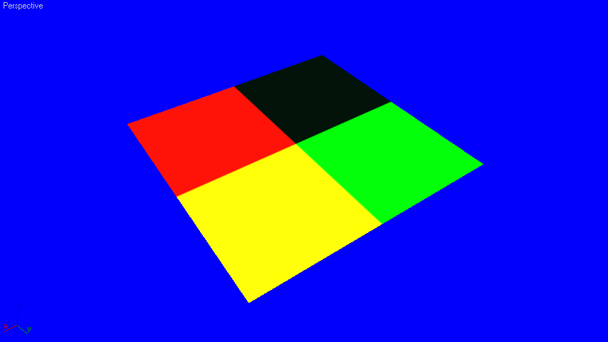
Visualizing a non-normalized value
In the illustration above, we display a non normalized value (the fragment plane space position in this case). Red color indicates positive x axis, green positive y axis, and blue positive z axis. Note that if our model had a negative offset we could end up with a black geometry, as any negative value outputs as zero. The result for a normalized value differs:
Visualizing a normalized value
Colors transitions are smooth, negative vector components are black. Note that vertex shader inputs are in object space, so the rendered result does not change when the camera is moving.
Checking a View Space Value
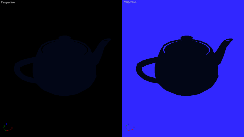
If we look at a view space vector, such as a light vector, the result moves for each camera movement. Non normalized values may appear quite strange as shown below.
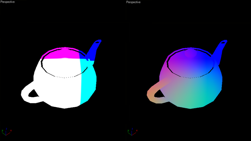
Visualization of a view space vector: non-normalized and normalized views
Moving values are often view space values. In view space, a vector will appear red if it’s headed right of our screen, green if it’s headed top of our screen and blue if it’s moving toward our camera position (view space uses +X as right camera vector, +Y as top camera vector, -Z as camera sight vector). In the sample screenshots above, the vector goes from the fragment position on the teapot to the light. Therefore, around the light position, the vector is fully moving toward our camera, and appears blue. In the lower left corner of our screen, the vector is headed top right and moving toward our camera: it’s white. In the upper left corner, the vector is moving right and toward the camera: it’s a mix of red and blue. The shader code used to produce that example is the following:
// Vertex shader program:
// ----------------------
//  o Inputs: state.matrix.program[2]: ocs2dcs matrix.
//            state.matrix.program[3]: ocs2vcs matrix.
//            program.local[0]: VCS light position reference.
//            vertex.attrib[0]: POSITION.
//
//  o Outputs: result.texcoord[0]: VCS light vector.

str.VertexShaderStart();

// Calculating the light vector in VCS:
str.Temp( "R0" );
str.VertexTransform( "R0", "state.matrix.program[3]", "vertex.attrib[0]" );
str.Add( "ADD result.texcoord[0], program.local[0], -R0;\n" );

// Output regular fragment position:
str.VertexTransform( "result.position", "state.matrix.program[2]", "vertex.attrib[0]" );

str.ShaderEnd();


// Pixel shader program:
// ---------------------
//  o Inputs: fragment.texcoord[0]: VCS light vector.

str.PixelShaderStart();

// Left screenshot:
str.Add( "MOV result.color, fragment.texcoord[0];\n" );

// Right screenshot:
str.Temp( "R0" );
str.Normalize( "R0","fragment.texcoord[0]" );
str.Add( "MOV result.color, R0;\n" );

str.ShaderEnd();
Checking a Tangent Space Value
In tangent space, such as for a bump mapping calculation, directions are relative to the local UV basis at the fragment. For the given picture, we have the following directions for the tangents:
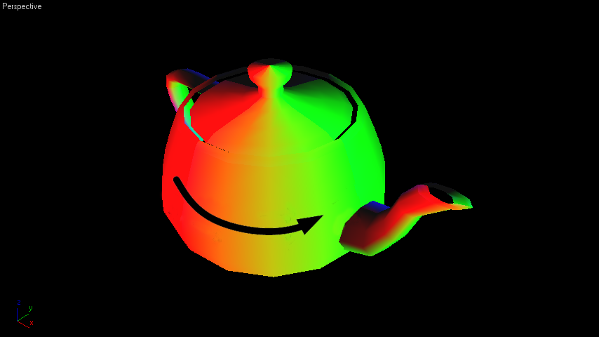
Tangents visualized in object space, are shown by the black arrow
Note
Directions are in object space, and therefore may not match the world axis system. The local basis associated to the tangent is completed by the normal, which is usually locally perpendicular to the surface at every fragment, and by the binormal, which results of the cross product of the two others.
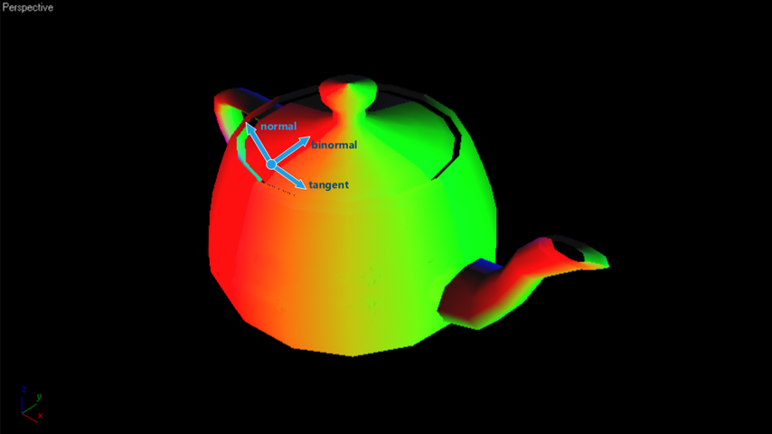
Representation of the tangent space basis in object space coordinates
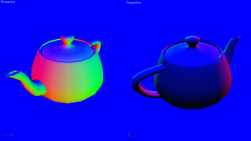
Then, when visualizing tangent space information (as a normal map in the example below), the colors are matching the tangent space basis: RGB matches (tangent, binormal, normal):
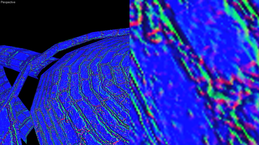
Normal vector displayed in tangent space and a close up view
In the picture above, red color points to the tangent direction, green color to the binormal direction, and blue color to the normal direction.
Different Behaviors on Different gPU back-ends
Namely, ATI and NVIDIA graphic boards may not behave identically when a given program is executed. The main reason for that is the behavior versus the non-initialized register read.
- NVIDIA drivers initialize all program temporaries to zero by default.
- ATI drivers don’t initialize any program temporary parameter.
Therefore, the behavior of the same program may differ on both vendors’ cards. Check that all used temporaries are properly initialized. The behavior differs with respect to all bound program locals. A program may try to read an unbound program local. In this case the value currently set in the corresponding register will be used for the program execution. Based on the rendering sequence, this may produce random results.