Picking
Introduction
This tutorial focuses on the base picking method available in HOOPS Luminate. This is RED::IWindow::FramePicking. This picking method, as detailed here: Picking, provides a lot of informations on all the items that are ‘under’ the picked position - which is generally set at the mouse coordinates - so that the appropriate action can be undertaken.
A Simple Scene Graph with Instances
We’ll start by the creation of a simple scene graph to illustrate how the picking function behaves. Note that our example scene graph uses two Instances of the cylinder, as shown in the image below:
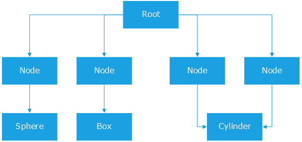
The source scene graph of our picking tutorial.
All materials are set on nodes rather than on geometries. This’ll be of importance for the highlighting workflow we’ll detail hereafter.
Calling the Picking Method
Nothing fancy out there:
RED::Vector< RED::ShapePath > picklist;

if( mx >= 0 && mx < width && my >= 0 && my < height )
{
    RC_TEST( iwindow->FramePicking( picklist, vrl, mx, my, NULL ) );
}
Results of the picking are a list of front-to-back sorted entities. There’s actually one RED::ShapePath instance for each picked shape found at the picked position, and each RED::ShapePath instance may contain several picked entities, that are also sorted front-to-back.
Setting Up an Overlay Camera
In HOOPS Luminate, there’s neither a default picking nor a default highlight workflow: any application can do whatever is appropriate with the picked data. In our tutorial, we’ll simply highlight the picked geometry. But we’ll do this so that we can see a picked geometry which is behind another geometry, using transparency. This is illustrated by the image capture below:
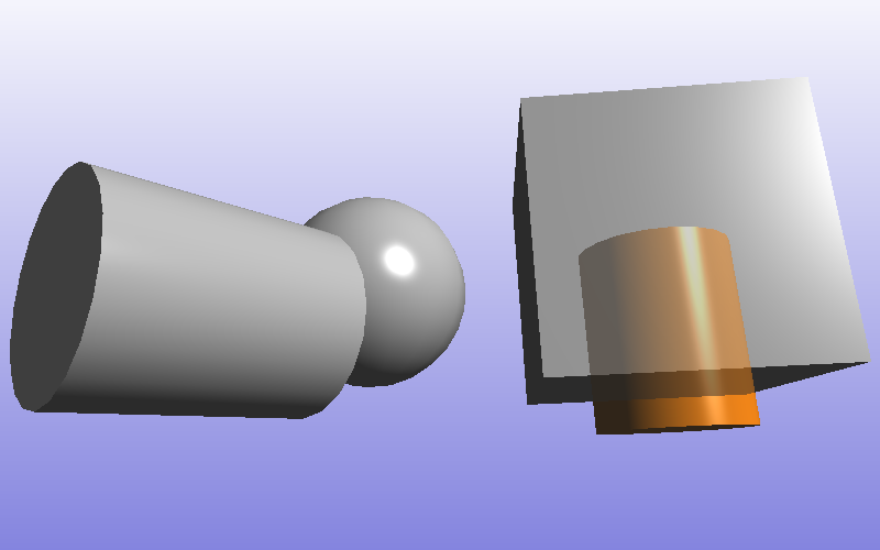
One cylinder instance was picked, and it appears behind the cube, in transparency.
Several scene graph architectures can lead to this kind of results, and we’ll only detail one possible solution in this tutorial: We’ll use one overlay camera to redraw the selected geometries over the scene:
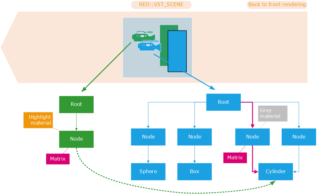
The overlay camera and its scene graph.
The overlay camera is created so that it’s rendered AFTER the scene camera. Therefore, at the time it gets displayed, the standard scene camera has been drawn already and the color and depth buffer of the default window VRL are filled with the original model (displayed with a grey material).
This is done at the insertion time of the overlay camera. The camera is in the RED::VST_SCENE list of the VRL (as the scene camera), but it’s inserted BEFORE it in the list, so that it gets rendered AFTER (the VRL renders cameras last to first):
RC_TEST( ivrl->InsertViewpoint( overlay_camera, RED::VST_SCENE, RED::LIST_FIRST,
                            0, 0, width, height, 0.0f, 0.0f,
                            RED::VSP_ANCHOR_FIXED, RED::VSP_SIZE_STRETCHED_AUTO_RATIO,
                            iresmgr->GetState() ) );
This overlay camera displays the picked shape using another scene graph. It does not duplicate the picked shape as it just points to it. Thanks to the RED::ShapePath contents, we can set the right transformation matrix to visualize the picked cylinder at the right position:
RED::Matrix matx;
RC_TEST( picklist[0].GetPathMatrix( matx ) );

RED::Object* node = RED::Factory::CreateInstance( CID_REDTransformShape );
if( !node )
    RC_TEST( RED_ALLOC_FAILURE );

RED::IShape* isnode = node->As< RED::IShape >();
RC_TEST( isnode->SetMaterial( g_highlight_matr, iresmgr->GetState() ) );

RED::ITransformShape* itnode = node->As< RED::ITransformShape >();
RC_TEST( itnode->SetMatrix( &matx, iresmgr->GetState() ) );

RC_TEST( ioverlay_camera->AddShape( node, iresmgr->GetState() ) );

if( g_pick_sub_objects == false )
{
    // If we do an object level picking, simply add the picked shape:
    RC_TEST( itnode->AddChild( picklist[0].GetLastShape(), RED_SHP_DAG_NO_UPDATE, iresmgr->GetState() ) );
}
The RED::ShapePath class can return the cumulated transformation matrix of the picked leaf shape, therefore, we can easily re-assign this matrix to another transform to directly reposition the picked cylinder instance properly. Then, thanks to the material inheritance rules (see Shape Attributes in a Scene Graph) in a scene graph, the cylinder being displayed by the overlay camera will use the highlight material set on the node above it in the scene graph of the overlay camera.
Seeing Picked Objects in Transparency
So, we have an overlay camera that displays the picked shape: one of the instanced cylinders in our illustrations above. This cylinder will be drawn after the scene, in the same color & depth buffer as the main scene because both cameras are in the same RED::VST_SCENE list of viewpoints in the same VRL. Ok.
So how does it appear before and behind the other scene geometries at the same time? To do this, we use a dual pass material:
RED_RC CreateHighlightMaterial( RED::Object*&     matr,
                            const RED::Color& color )
{
    RED::Object* resmgr = RFK::TutorialApplication::GetResourceManager();
    RED::IResourceManager* iresmgr = resmgr->As< RED::IResourceManager >();

    RC_TEST( iresmgr->CreateMaterial( matr, iresmgr->GetState() ) );
    RED::IMaterial* imatr = matr->As< RED::IMaterial >();

    RED_RC rc;

    // Front highlight shader:
    RED::RenderShaderViewport rsh_front( RED::MTL_PRELIT,
                                        RED::RSV_TRIANGLE,
                                        false,
                                        RED::MCL_COLOR,
                                        color * 0.9f,
                                        color * 0.1f,
                                        RED::Color::WHITE,
                                        30.0f,
                                        RED::Color::WHITE,
                                        RED::Color::WHITE,
                                        resmgr,
                                        rc );
    rsh_front.SetID( "front" );

    RC_TEST( imatr->RegisterShader( rsh_front, iresmgr->GetState() ) );
    RC_TEST( imatr->AddShaderToPass( rsh_front.GetID(), RED::MTL_PRELIT, RED::LIST_LAST, RED::LayerSet::ALL_LAYERS, iresmgr->GetState() ) );


    // Back highlight shaders:
    RED::StateShader ssh_back;
    RC_TEST( ssh_back.SetDepthTest( RED::StateShader::ON ) );
    RC_TEST( ssh_back.SetDepthFunction( RED::StateShader::GREATER ) );
    RC_TEST( ssh_back.SetDepthMask( RED::StateShader::OFF ) );
    RC_TEST( ssh_back.SetBlendingMode( RED::StateShader::CUSTOM,
                                        RED::StateShader::CONSTANT_COLOR,
                                        RED::StateShader::ADD,
                                        RED::StateShader::ONE_MINUS_CONSTANT_COLOR ) );
    RC_TEST( ssh_back.SetBlendingConstant( RED::Color( 0.5f ) ) );

    RC_TEST( imatr->RegisterShader( ssh_back, iresmgr->GetState() ) );
    RC_TEST( imatr->AddShaderToPass( ssh_back.GetID(), RED::MTL_PRELIT, RED::LIST_LAST, RED::LayerSet::ALL_LAYERS, iresmgr->GetState() ) );

    RED::RenderShaderViewport rsh_back( RED::MTL_PRELIT,
                                        RED::RSV_TRIANGLE,
                                        false,
                                        RED::MCL_COLOR,
                                        color * 0.9f,
                                        color * 0.1f,
                                        RED::Color::WHITE,
                                        30.0f,
                                        RED::Color::WHITE,
                                        RED::Color::WHITE,
                                        resmgr,
                                        rc );
    rsh_back.SetID( "back" );

    RC_TEST( imatr->RegisterShader( rsh_back, iresmgr->GetState() ) );
    RC_TEST( imatr->AddShaderToPass( rsh_back.GetID(), RED::MTL_PRELIT, RED::LIST_LAST, RED::LayerSet::ALL_LAYERS, iresmgr->GetState() ) );

    return RED_OK;
}
The first shader renders the geometry using the highlight color. It’s rendered in orange. Because the overlay camera is rendered after the scene camera, this shader pass will overlap the actual scene geometry. This is related to the Default Pass Startup State Shader Configurations we have for the RED::MTL_PRELIT pass: we can render the same geometry several times, the last rendered geometry will overlap the previous one, thanks to the RED::StateShader::LEQUAL depth function being used.
The second shader renders the geometry using a simple blending equation: CONSTANT_COLOR * SRC_COLOR + ( 1 - CONSTANT_COLOR ) * DST_COLOR. Due to the RED::StateShader setup of this second pass, the second rendering pass will only show a result when the rendered geometry is BEHIND something else (hence the RED::StateShader::GREATER depth function selection for this pass).
Picking Primitive Entities in Shapes
So far, we have picked plain shapes. If we press the polygon toolbar button in the tutorial, this’ll toggle the picking of sub-entities to reveal the contents we have in a RED::ShapePath object. As our scene is made of triangles, RED::ShapePath objects contain triangles. This second codepath creates a transient shape to show the closest picked triangle in the first picked shape:
// We must have at least picked something!
if( picklist[0].GetItemsCount() == 0 )
    RC_TEST( RED_FAIL );

const RED::ShapePath::LeafData& item = picklist[0].GetFirstItem();

// If we do an entity level picking, we create a shape for the display of the picked entity (a triangle here):
RED::Object* tri = RED::Factory::CreateInstance( CID_REDMeshShape );
if( !tri )
    RC_TEST( RED_ALLOC_FAILURE );

RED::IMeshShape* imtri = tri->As< RED::IMeshShape >();

float vertex[9], normal[9];

vertex[0] = (float)item._p0._x; vertex[1] = (float)item._p0._y; vertex[2] = (float)item._p0._z;
vertex[3] = (float)item._p1._x; vertex[4] = (float)item._p1._y; vertex[5] = (float)item._p1._z;
vertex[6] = (float)item._p2._x; vertex[7] = (float)item._p2._y; vertex[8] = (float)item._p2._z;

RED::Vector3 p01, p02, n;
p01 = item._p1 - item._p0;
p02 = item._p2 - item._p0;
n = p01.Cross2( p02 );

normal[0] = (float)n._x; normal[1] = (float)n._y; normal[2] = (float)n._z;
normal[3] = (float)n._x; normal[4] = (float)n._y; normal[5] = (float)n._z;
normal[6] = (float)n._x; normal[7] = (float)n._y; normal[8] = (float)n._z;

RC_TEST( imtri->SetArray( RED::MCL_VERTEX, vertex, 3, 3, RED::MFT_FLOAT, iresmgr->GetState() ) );
RC_TEST( imtri->SetArray( RED::MCL_NORMAL, normal, 3, 3, RED::MFT_FLOAT, iresmgr->GetState() ) );

int index[3] = { 0, 1, 2 };

RC_TEST( imtri->AddTriangles( index, 1, iresmgr->GetState() ) );

RC_TEST( itnode->AddChild( tri, RED_SHP_DAG_NO_UPDATE, iresmgr->GetState() ) );
Deep Picking
The results returned by RED::IWindow::FramePicking contain all the found entities under the picked coordinates: so all triangles, lines, points, texts for all shapes found are returned by the method.

