Creating Panorama
Introduction
This tutorial is about panorama creation with HOOPS Luminate, also called environment map creation. We will render the six faces of a cube image (see RED::IImageCube) in software and apply this cube as background in a hardware rendered scene. An auxiliary VRL will be used to do offscreen software rendering of the 3D scene while the main VRL will do the hardware rendering of the panorama.
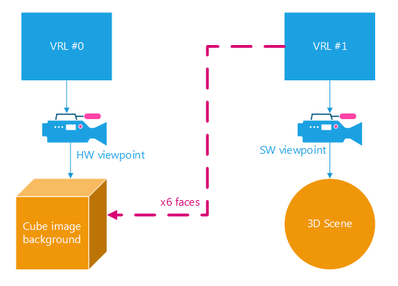
VRL and viewpoint organization of the tutorial
During the final stage of the tutorial, we will use the GPU to create a spherical environment map and save it as a .png image.
The scene is really simple -as always with the tutorials- and composed of the classical 3D primitives.
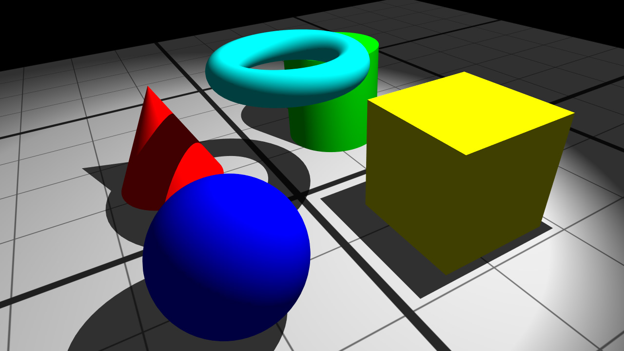
Tutorial scene
Rendering the Scene to an Offscreen VRL
The main principle of panorama creation is to consecutively render the 6 faces of the cube. A viewpoint is configured for this task:
// FOV is 2PI / 4 / 2 because of the half angle.
// Aspect ratio is 1: the faces are squares, HFOV = VFOV.
RC_TEST( icamera->SetFrustumPerspective( RED_PI * 0.25, 1.0, iresmgr->GetState() ) );
// The first face to draw is the +X one.
RC_TEST( icamera->SetViewingAxis( RED::Vector3::XAXIS, -RED::Vector3::YAXIS, -RED::Vector3::ZAXIS, iresmgr->GetState() ) );
The camera field of view (half angle) have to be 2PI / 8 as shown on the following figure. The aspect ratio is 1 because the horizontal FOV is equal to the vertical one.
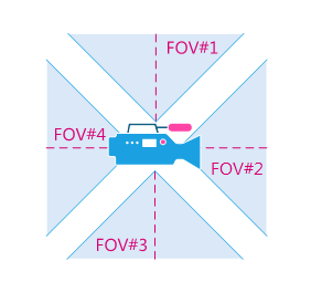
Viewpoint FOV to fill the entire space are PI / 4
The software rendering needs to be activated for this viewpoint via the RED::IOptions interface:
// Enable software rendering and options:
RED::IOptions* icamopt = camera->As< RED::IOptions >();
RC_TEST( icamopt->SetOptionValue( RED::OPTIONS_RAY_PRIMARY, true, iresmgr->GetState() ) ) ;
RC_TEST( icamopt->SetOptionValue( RED::OPTIONS_RAY_REFLECTIONS, 2, iresmgr->GetState() ) );
RC_TEST( icamopt->SetOptionValue( RED::OPTIONS_RAY_REFRACTIONS, 2, iresmgr->GetState() ) );
RC_TEST( icamopt->SetOptionValue( RED::OPTIONS_RAY_TRANSPARENCY, 2, iresmgr->GetState() ) );
RC_TEST( icamopt->SetOptionValue( RED::OPTIONS_SHADOW_MAP_DEPTH, 3, iresmgr->GetState() ) );
RC_TEST( icamopt->SetOptionValue( RED::OPTIONS_RAY_SHADOWS, 3, iresmgr->GetState() ) );
For each face, we will need to set the viewing axis. The camera axis that need to be set as well as the cube face indices are documented in the RED::IImageCube page.
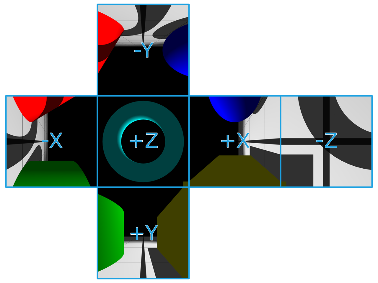
The cube faces and sight axis
Note
Of course, the viewpoint needs to contain the scene graph. In this tutorial we use the default camera created with the scene, so everything is already ok. If you want to create a new camera, don’t forget to add the scene under it.
Once our camera is correctly set up, the next step is to create the auxiliary RED::IViewpointRenderList that will render the scene. The viewpoint is inserted in this VRL.
// New VRL:
RC_TEST( iwindow->CreateVRL( g_cube_vrl, g_cube_size, g_cube_size, RED::FMT_RGBA, true, iresmgr->GetState() ) );
RED::IViewpointRenderList* ivrl = g_cube_vrl->As< RED::IViewpointRenderList >();

RC_TEST( ivrl->InsertViewpoint( camera, iresmgr->GetState() ) );
RC_TEST( ivrl->SetClearColor( RED::Color::BLACK, iresmgr->GetState() ) );
RC_TEST( ivrl->SetSoftAntiAlias( 4, iresmgr->GetState() ) );
Creating the Panorama Scene
The first thing to do in the hardware scene part is to create the viewpoint and the background cube:
// Create a new camera for the visible hardware scene:
RED::Object* cam = RED::Factory::CreateInstance( CID_REDViewpoint );
if( cam == NULL )
    RC_TEST( RED_ALLOC_FAILURE );
// Create the cube image. It will be used to set as background of the main VRL.
RC_TEST( iresmgr->CreateImageCube( g_cube_image, iresmgr->GetState() ) );
RED::IImageCube* icube = g_cube_image->As< RED::IImageCube >();
These two objects will be added to the default VRL provided by the RFK::TutorialApplication.
// Define it as main camera:
RC_TEST( RFK::TutorialApplication::SetViewpoint( cam ) );

// Set the panorama cube image as background of the main VRL:
RED::Object* vrl;
RC_TEST( iwindow->GetDefaultVRL( vrl ) );
ivrl = vrl->As< RED::IViewpointRenderList >();
RC_TEST( ivrl->SetBackgroundImages( g_cube_image, RED::Matrix::IDENTITY, NULL, RED::Matrix::IDENTITY, true, 1.0, 1.0, iresmgr->GetState() ) );
RC_TEST( ivrl->SetEngineAntiAlias( 4, true, iresmgr->GetState() ) );
From now, our hardware rendered scene is ready.
Filling the Cube Image with the Scene Views
At this point we have:
- An auxiliary VRL which renders the scene in software
- The primary VRL containing an empty cube image as background
The last operation is to fill the cube with the images calculated by the auxiliary VRL. The RFK::TutorialApplication allows to define a function called when the rendering is over via the RFK::EVT_RENDER_COMPLETE event.
For each six rendered face, we have to:
- Retrieve the calculated image via the
RED::IViewpointRenderList::GetRenderImagefunction- Copy this image into the cube image with
RED::IImageCube::SetFacePixels- Define the next face to render by setting the viewpoint axis:
RED::IViewpoint::SetViewingAxis- Relaunch the rendering by calling
RFK::TutorialApplication::Invalidate
The following code shows how to copy the VRL result image into the cube image:
// Get the calculated render image:
RED::IViewpointRenderList* ivrl = g_cube_vrl->As< RED::IViewpointRenderList >();
RED::Object* renderimg = ivrl->GetRenderImage();
RED::IImage2D* irenderimg = renderimg->As< RED::IImage2D >();

// Get the face pixels:
RC_TEST( irenderimg->GetPixels() );
unsigned char* pix = irenderimg->GetLocalPixels();

// Set the pixels to the cube image:
RED::IImageCube* icube = g_cube_image->As< RED::IImageCube >();
RC_TEST( icube->SetFacePixels( g_current_face-1, pix, g_cube_size, RED::FMT_RGBA, iresmgr->GetState() ) );
Bonus: Creating a Spherical Environment Map
In the last part of this tutorial, the RED::IImageCube will be used to create and save a spherical environment map. The calculation will be done in GPU using a pixel shader program.
Like we have done in the previous step, a third auxiliary VRL is created. It contains an orthographic camera and renders a quad of the size of the spherical map. A custom material must be defined for this quad. Its purpose is to draw the spherical map on the quad given the cube map as input. The vertex shader is the simplest we can write and simply transfers the vertex position and texture coordinates. The pixel shader is used to do the cube mapping:
// Pixel shader:
//  - All the conversion from cube map to spherical map is done here:
//  - Conversion from spherical to cartesian (radius 1):
//    x = sin theta * cos phi
//    y = sin theta * sin phi
//    z = cos theta
program.PixelShaderStart();
program.Temp( "texcoord" );
program.Temp( "trigo" );
program.Add( "MOV texcoord, fragment.texcoord[0];\n" );
// phi [0;2PI]
program.Add( RED::String( "MUL texcoord.x, texcoord.x, {%1}.x;\n" ).Arg( RED_2PI ) );
// theta [0;PI]
program.Add( RED::String( "MUL texcoord.y, texcoord.y, {%1}.x;\n" ).Arg( RED_PI ) );
// invert phi
program.Add( RED::String( "SUB texcoord.x, {%1}.x, texcoord.x;\n" ).Arg( RED_2PI ) );
// invert theta
program.Add( RED::String( "SUB texcoord.y, {%1}.x, texcoord.y;\n" ).Arg( RED_PI ) );
// cos phi
program.Add( "COS trigo.x, texcoord.x;\n" );
// sin phi
program.Add( "SIN trigo.y, texcoord.x;\n" );
// cos theta
program.Add( "COS trigo.z, texcoord.y;\n" );
// sin theta
program.Add( "SIN trigo.w, texcoord.y;\n" );
// x = sin theta * cos phi
program.Add( "MUL texcoord.x, trigo.x, trigo.w;\n" );
// y = sin theta * sin phi
program.Add( "MUL texcoord.y, trigo.y, trigo.w;\n" );
// z = cos theta
program.Add( "MOV texcoord.z, trigo.z;\n" );
// cube mapping
program.Add( "TEX result.color, texcoord, texture[0], CUBE;\n" );
program.Add( "MOV result.color.a, {1.0}.x;\n" );
program.ShaderEnd();
To finish, a single call to RED::IWindow::FrameDrawing is sufficient to render our spherical map. Like in the previous section, it can be retrieved using RED::IViewpointRenderList::GetRenderImage.
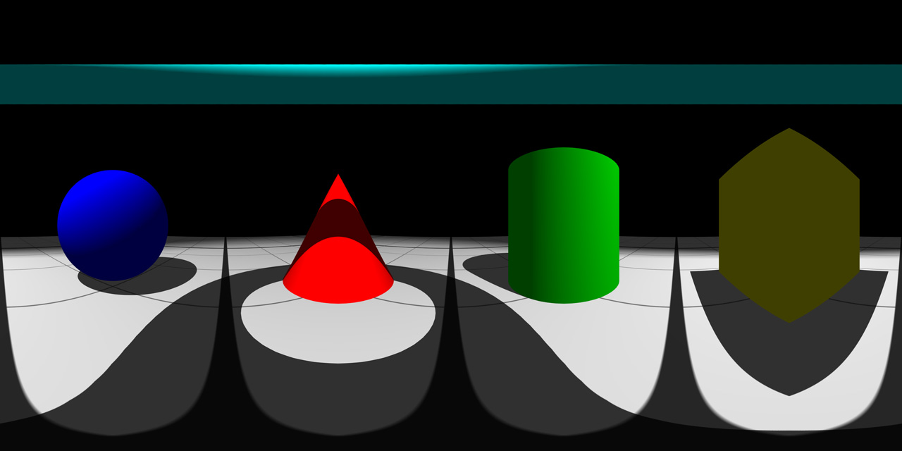
Final spherical environment map
Note
Important! In this example, we choose to invert phi to have a visually correct, not inverted, spherical map image. If you re-apply it directly to a cube with the RED::IImageCube::CreateEnvironmentMap function, the scene will be inverted because HOOPS Luminate uses a positive rotation for phi (see function documentation).

