Configuring a Render Shader Using a State Shader
The RED::StateShader object is used to configure the rendering pipeline. State shaders are added to a RED::MATERIAL_PASS like any other shader and configure all the following RED::RenderShader until new state shaders are encountered in the pipe.
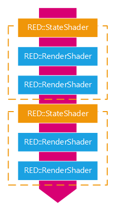
The state shader configures the following render shaders in the pipeline
The state shader manages hardware state parameters and some ray-tracer parameters and support multiple platforms. This page will list all the RED::StateShader features.
Displacement
State shaders are used to perform displacement mapping. This technique is similar to the bump mapping but really modifies the surface of the rendered objects.
The RED::StateShader::SetDisplacement method allows to set a displacement map for the rendering of an object. Displacement maps are special textures used to define elevation values.
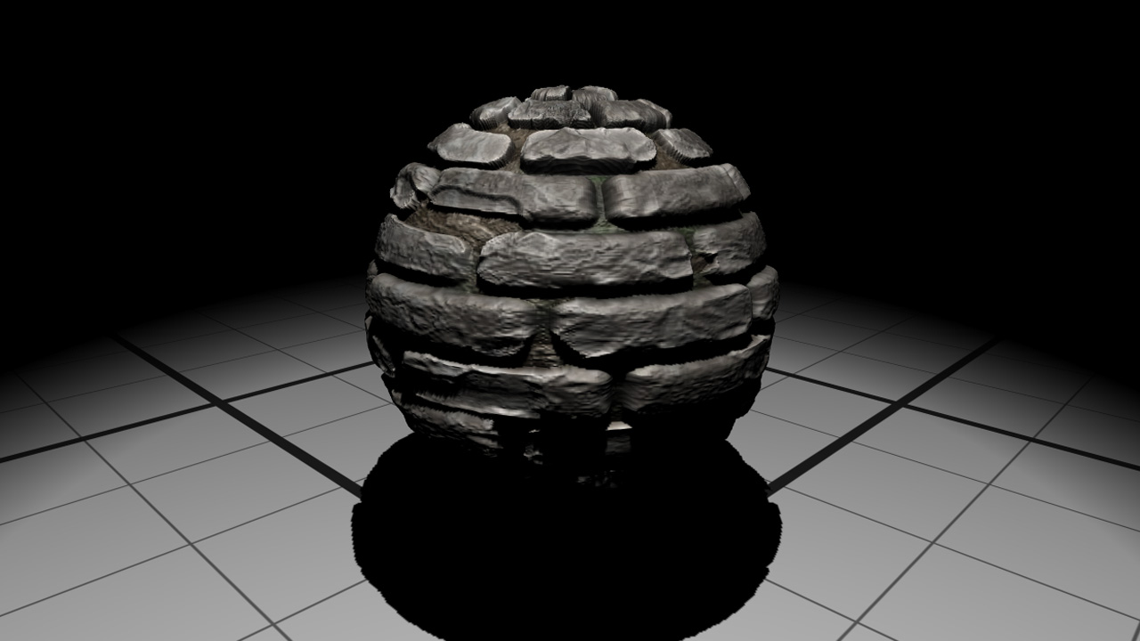
A simple sphere with displacement mapping
When using displacement mapping, be sure the the RED::OPTIONS_RAY_DISPLACEMENT option is set as enabled.
Note
The displacement mapping is currently only available in software rendering.
Transparency
Blending can be used to make objects appear transparent. However blending is not sufficient. Depending on the rendering order of the scene objects, the renderer may fail to render things correctly behind transparent objects. Transparency needs to be sorted.
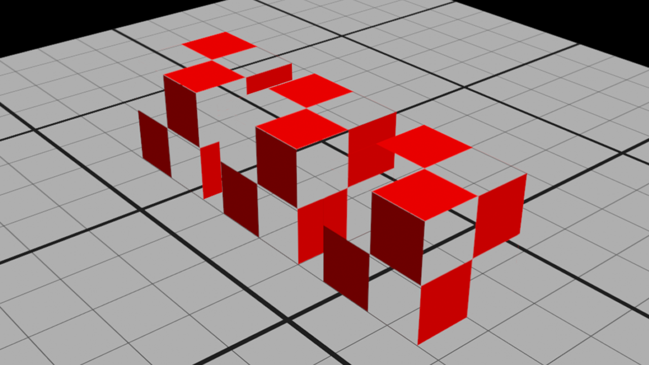
Transparency issue between the two furthest cubes
In the previous picture, the two nearest transparent cubes are rendered in the correct order, the blended transparency is handled well contrary to the two furthest cubes which are not rendered correctly.
The RED::StateShader::SetSortedTransparency method defines a per pixel depth sorted transparency. Transparency may be defined using an opacity color where each channel holds its proper opacity or an opacity texture. The alpha channel or the opacity color is not used.
To completely disable the transparency, the state shader provides the RED::StateShader::SetNoTransparency function. By calling it, you indicate that the material is not transparent at all.
Alpha Masking
Quite often, the transparency is a binary decision. Either pixel is fully opaque or fully transparent. For instance, when drawing grass, you probably can’t afford a polygon for each blade of grass; so you use alpha masking combined with an image of the blades.
The RED::StateShader::SetMaskedTransparency takes an alpha texture and defines the transparency from it. The alpha channel of the texture is used to define transparency values.
With the RED::StateShader::SetAlphaThreshold function, a user can then indicate the threshold under which the alpha mask texel is completely transparent and over which it is fully opaque.
Color Masking
Sometimes, you don’t want to write in the frame buffer. For instance to write exclusively in the depth buffer or in the stencil buffer.
HOOPS Luminate provides a method to do the color masking: RED::StateShader::SetColorMask. Using this function allows to prevent writing in one or more channel of the color buffer.
Blending
The RED::StateShader primary function is to define how the following RED::RenderShader will write in the framebuffer. In order to define how the blending has to be done, we can use the following method: RED::StateShader::SetBlendingMode.
This function allows to set the RED::StateShader::BLENDING_MODE.
In case of a custom blending mode (RED::StateShader::CUSTOM), we give the ability for a user to define his own using blending functions (RED::StateShader::BLENDING_FUNCTION) and equation (RED::StateShader::BLENDING_EQUATION).
Given the RED::StateShader::SetBlendingMode parameters:
- iFunction1: the function applied to the source color (incoming fragment).
- iOperation: the operation to perform between the source and the destination colors.
- iFunction2: the function applied to the destination fragment color.
the blending formula is always: iFunction1(src_color) iOperation iFunction2(dest_color).
Example: for the following operation: color = 0 * src_color + ( 1 - src_color ) * dest_color
iFunction1 = ZERO
iOperation = ADD
iFunction2 = ONE_MINUS_SRC_COLOR
Finally, some blending functions use a constant value:
RED::StateShader::CONSTANT_COLORRED::StateShader::ONE_MINUS_CONSTANT_COLORRED::StateShader::CONSTANT_ALPHARED::StateShader::ONE_MINUS_CONSTANT_ALPHA
This constant value can be set using the RED::StateShader::SetBlendingConstant function.
Stenciling
The stencil buffer, like the depth buffer, is another buffer for a custom use. It stores per-pixel information and indicates to the renderer to act differently according to its values. It can prevent the renderer from writting to the color buffer under given conditions.
The usage of stencil buffer is however subject to several hardware restrictions. Please look here for all details: Known Hardware Issues in the section No Stencil Buffer on Auxillary VRLs.
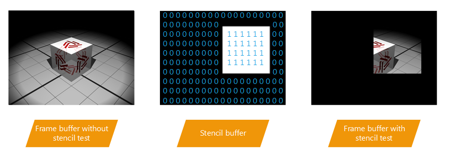
Example of stencil buffer usage to clip the rendering
To enable or disable the stencil test, you can use the RED::StateShader::SetStencilTest function.
The stencil buffer is manipulated using the two functions:
RED::StateShader::SetStencilFunctionRED::StateShader::SetStencilOperation
The stencil function specifies a test to apply to each pixel of the stencil buffer. The stencil operation specifies the action to do depending on the test result.
According to its three parameters:
- iFunc: the comparison function (
RED::StateShader::FUNCTION) - iRef: the reference integer used in the comparison
- iMask: a mask applied to iRef and to the stencil pixel; to disable it, set 0xFF
the following test is executed: ( iRef & iMask ) iFunc ( stencil_buffer & iMask ).
Depending on the result of this test, the stencil operation (RED::StateShader::STENCIL_OPERATION) defines the action to do on the stencil buffer:
- when the stencil test fails
- when the stencil test passes but the depth buffer test fails
- when both tests passes
In the first two cases, the fragment buffer is left unchanged as the tests fail. The last case where both tests worked is the only one to evaluate the fragment buffer in the color buffer.
Finally, the RED::StateShader::SetStencilMask allows to change the stencil writemask value. Setting it to 0xFF will always write in the stencil buffer whereas setting it to 0x00 will prevent writing in any condition.
Depth Control
The depth buffer is another buffer like the stencil and the color ones. It allows to keep track of the depth of every pixel on the screen. The depth is proportional to the distance between the screen plane and the drawn fragment. During the rendering, if the fragment is closer than the one already drawn, it will be drawn over. The fragment shader will not run for invisible fragments, which is a good thing for the performance.
This is called depth testing and can be enabled or disabled using the following function: RED::StateShader::SetDepthTest.
The depth test function can be changed using the RED::StateShader::SetDepthFunction method. By default and to have the previously described behavior, the function (RED::StateShader::FUNCTION) is set to ‘lower of equal’ (RED::StateShader::LEQUAL).
The RED::StateShader::SetDepthMask function enables or disables the writing in the depth buffer.
Double Side Control
It is sometimes useful to draw both sides of a polygon, e.g. when dealing with transparency. The RED::StateShader allows to activate the rendering of both sides of the polygons with the RED::StateShader::SetDoubleSided method.
Note
This method renders the geometry twice, be warned that it could be harmful for the rendering performance.
Another function can be used to render both faces of the polygons: RED::StateShader::SetFaceCulling. This method allows to define the drawn faces by setting the culling mode (RED::StateShader::CULLING_MODE):
- draw only front face by culling the back face (
RED::StateShader::BACK)- draw only back face by culling the front face (
RED::StateShader::FRONT)- or draw both faces by not culling anything (
RED::StateShader::NONE)
Note
Unlike the first method, this one could be better for performance as both faces are drawn in a single pass.
Render Styles for Lines and Points
Several functions of the state shader are related to the line an point primitives.
The line primitive (RED::ILineShape) options are:
RED::StateShader::SetLineWidth: sets the width of the lines.RED::StateShader::SetLineSmoothing: enables or disables the smoothing of the line.RED::StateShader::SetLineStipple: used to activate stippled (dotted or dashed) lines.RED::StateShader::SetLineStipplePattern: defines the pattern of the line stipple.
The point primitive (RED::IPointShape) options are:
RED::StateShader::SetPointSize: sets the size of the point as its name suggests.RED::StateShader::SetPointSmoothing: enables or disables the smoothing of the point.
Polygon Offset
Polygon offset option is useful to avoid geometry stitching, bleeding or z-fighting when polygons are overlapping. With depth test enabled, some pixels passes the depth test, while some fails leading to visual artefacts.

Z-fighting between two coplanar polygons
The polygon offset will alter the correct depth value calculated during rasterization, the resulting z value stored in the depth buffer will contain this offset and can adversely affect the resulting image.
The RED::StateShader::SetPolygonOffset function activates the option. The RED::StateShader::SetPolygonOffsetValue defines the polygon offset values.
This option is widely used to prevent edges of a mesh to be z-fighting with the geometry when edge rendering is enabled.
Note
This option works only on triangle based mesh (RED::ImeshShape).
Caustics Enabling
The RED::StateShader contains functions to enable the generation of caustics.
RED::StateShader::SetReflectiveCausticsenables the reflective caustics.RED::StateShader::SetRefractiveCausticsenables the refractive caustics.
Matte Mode
When a material has the matte mode set to true, it is considered as not being lit directly. Instead, it receives shadows cast by the other objects in the scene as well as their global illumination contribution.
Matte objects are useful when rendering synthetic objects into real-world photographs for example.
The activation of the matte mode can be done with the RED::StateShader::SetMatte function and with the use of custom shaders that can be found in the HOOPS Luminate material library. See here Using HOOPS Luminate’s Library of Materials for details.
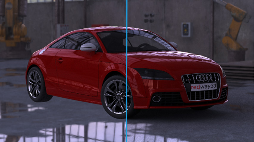
No matte shadows on the left versus matte shadows on the right
In the previous picture, see how the car is much better integrated in the scene when matte mode is activated in the ground plane material.

