Hardware vs. Software Rendering
HOOPS Luminate is a hybrid engine: it can process the same dataset using a hardware based rendering approach or a software rendering approach, both at the same time and even in the same window. This approach allows very flexible application designs. However, before we get into the details of each engine and how it’s used, we’ll take the opportunity of these pages to review the different rendering techniques involved.
A Word on Scanline and Z-Buffer Rendering
The scanline algorithm used with a z-buffer is a visible surface determination algorithm at the heart of all hardware accelerated GPUs. All polygons to render in the scene are projected on screen and then scanned for each pixel row and pixels they cover.
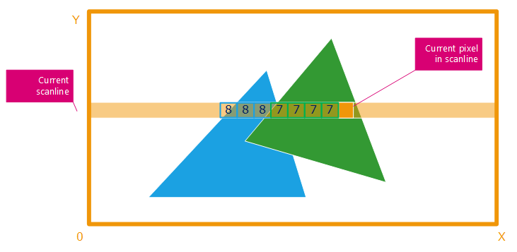
A scanline example
The algorithms then computes the depth of the current polygon seen from the camera, after screen projection (see Matrix Transforms in a Cluster) and keeps the closest polygon from the camera. In the example above, if the blue polygon is at depth = 8, then on rendering the green polygon which is at depth = 7, each pixel covered by the green polygon will be kept instead of the blue.
This algorithm is directly wired in today’s GPUs. That’s why millions of triangles can be rendered in large resolution at more than 100 frames per second!
That being said, what are the key points in such a rendering technique. All these are very important in the design and understanding of GPU based rendering solutions:
- The algorithm is cumulative. More polygons to draw means more polygons to scanline. The performance is expected to drop linearly as the number of polygons to render increases. This explains why there are many culling techniques out there to avoid processing unnecessary polygons.
- More rendering passes mean more polygons to draw, and we’re back to bullet point no 1. Extra lights cause extra rendering passes, and part of the scene may be rendered again to add the contribution of a new light.
- This approach is GPU centric. This means that the GPU can work while the CPU idles and can be used for something else needed by the application.
- GPU rendering is sensitive to screen resolution of course. However, due to hardware encoding of the z-buffer and pixel filling phase, GPUs do resist well to an increased number of pixels to render.
A Word on Ray-Tracing
Ray-tracing is an entirely different technique. It’s based on the propagation of individual rays in the scene, as illustrated below:
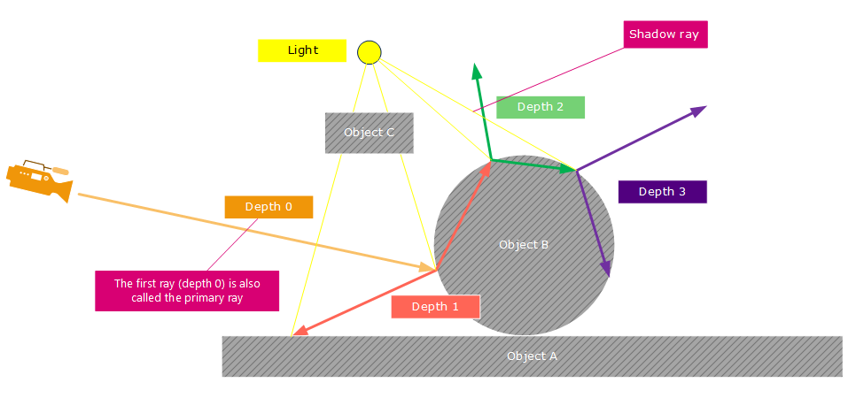
A recursive ray-tracing example
The process is per pixel. A ray is fired through each pixel of the camera image plane into the model. The ray is checked against the entire scene to find which triangle is hit first. Then additional effects (as shown above: reflections, refractions, shadows) can be added by simply casting more rays into the scene to gather useful informations. Of course, each ray is not directly checked against the entire model for visibility determination. An acceleration structure is used to optimize the amount of calculations needed per ray.
This algorithm behaves differently compared to z-buffering:
- More polygons don’t necessary mean more time to render the scene. Due to the acceleration structure, extra polygons may have little effect on the render time. In ray-tracing, adding millions of polygons behind a wall won’t change the render time, unlike with z-buffer solutions for which invisible polygons may need to be processed if they could not be culled away.
- The shading is not cumulative: it’s performed as a whole on the shaded point. This part usually takes less time than propagating rays into the scene.
- This approach is CPU centric: the GPU idles while - generally - all CPU cores are rendering the image in parallel.
- Ray-tracing is very sensitive to screen resolution. The performance is directly related to the number of pixels to process.
- Ray-tracing acceleration structure cost memory, and needs to be updated on dynamic data changes. This can take some time.
- Ray-tracing is natively capable of rendering photo-realistic images and can simulate a lot of effects that are unreachable to scanline based rendering solutions using a GPU.
- And finally, ray-tracer based images - with a decent photo-realistic quality - can’t be rendered in real-time on mainstream hardware.
Progressive Refinement using Ray-Tracing
Because ray-tracing is slow - calculating a ray and all the ray-tree behind a pixel takes some time - images can take minutes or hours to render. Many parameters will influence the rendering time: size of the model to process, rendering options, resolution, number of CPU cores available, etc…but in the end, an image with a good quality will take time to render. So we speak of offline rendering here.
Despite the time needed to process an image, HOOPS Luminate can deliver a feedback to users about the image being calculated. This is the ‘progressive refinement’ that is drawn by HOOPS Luminate on calling a software rendering method (RED::IWindow::FrameTracing and derived methods). Progressive refinement is a convenient way to get an overview of the final image before it gets calculated. Consequently, changes can be done earlier, without having to wait for the image to be completed before launching another rendering. There are several feedback modes available in HOOPS Luminate, and here’s below an example of a typical feedback:
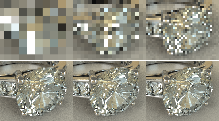
A progressive refinement example.
First feedback after one second is the top left image, and the refinement continues until we reach the bottom right final image.
Ray-Tracing or Z-Buffer?
Then, what rendering technique should be chosen for an application’s graphic needs? The answer is simply: it depends…
Real-time application will need the GPU to render 30-60 images per second. No choice. Photo-realistic imaging applications will need a software ray-tracing approach for quality reasons (GI, sampling, caustics, etc…). Many applications will need both: a workable environment using the graphic hardware and a photo-realistic rendering module. These will use both technologies available in HOOPS Luminate.
However, thanks to HOOPS Luminate’s hybrid approach, GPU operations can be beneficial to software rendering and vice versa: For instance, GPU tonemapping can be enabled to post-process any image rendered in software, in real-time. Ray-tracing can be used to pre-process ambient occlusion data used in the context of a real-time application. There are many examples of such technology sharing that can be helpful to a given application. That’s a key strength of HOOPS Luminate to aggregate different rendering solutions into a single product.
Combining Hardware Rendering and Software Rendering
Mixing Hardware and Software Rendering
The choice of one or another rendering methods in HOOPS Luminate is done at the viewpoint level and by choosing the appropriate rendering method for the window. If we are to render in software, then we’ll need to call RED::IWindow::FrameTracing (or any FrameTracingXXX method). This method will ensure that scenes can be rendered in software. Then, to render in hardware too, simultaneously, we’ll also need to ensure that HOOPS Luminate can process GPU images. Consequently, HOOPS Luminate needs to be started in hybrid mode: Hardware or Software Startup).
Then, the determination of whether a viewpoint will be processed in software ray-tracing or using the GPU will be made based on options enabled for that viewpoint:
- If the viewpoint has no ray-tracing options turned on, it’ll be rendered using the GPU
- If the viewpoint has ANY ray-tracing option turned on, it’ll be rendered using the CPU
During each call to RED::IWindow::FrameTracing, HOOPS Luminate will:
- Further refine the CPU image (the rendering of this camera will continue until finished)
- Render the GPU camera image
- Blend the two resulting images according to the camera setup in the VRL (which one is front or back, etc…)
Hardware Accelerated Ray-Tracing in HOOPS Luminate
As we have seen, HOOPS Luminate has two main rendering engines:
- A hardware accelerated z-buffer based rendering solution, suitable for any GPU based application.
- A software ray-tracing solution, based on parallelization and intensive usage of all CPU cores available in the host computer.
But it also has a third component, which is a hardware accelerated ray-tracing engine. This component is enabled on turning on a ray-tracer option while rendering using RED::IWindow::FrameDrawing (which is the standard GPU rendering call). HOOPS Luminate’s GPU ray-tracer render images fast for simple ray-tracing effects, but can’t reach a very high quality. It supports: reflections, refractions, shadows, soft shadows and glossiness. It does not support global illumination and caustics.
Z-Fighting Artifacts
Z-fighting artifacts arise when two overlapping but different polygons fight each other for visibility:
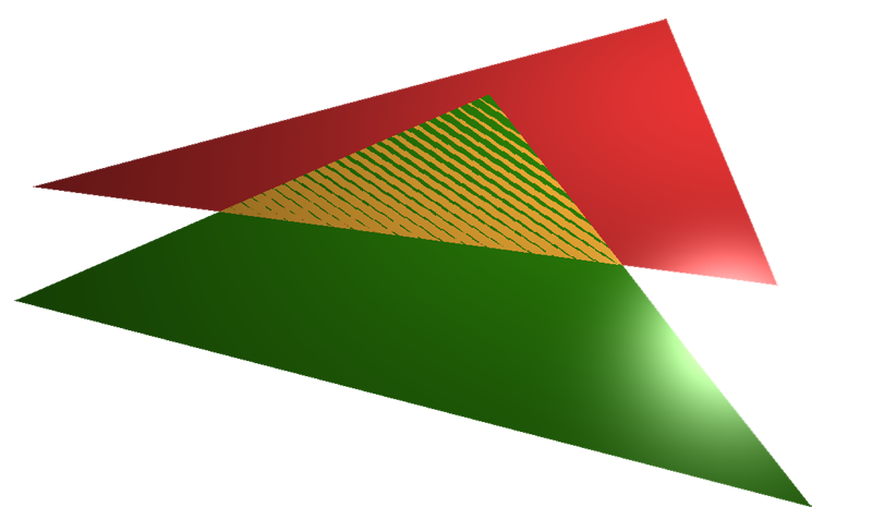
An example of z-fighting: the two polygons are on the z = 0 plane.
The source of z-fighting is the lack of transform invariance for two polygons. We’ve seen that the z-buffer algorithm used a scanline to process each polygon. Two different polygons generate different scanline boundaries and therefore there’s no reason for the two scanlines to produce the exact same accumulated depth value for a given pixel (the scanline is processed by interpolation using additive pixel steps). Those are very close, and alternatively one or the other polygon may be closer. Ray-tracing algorithms may exhibit the same problems too due to the fact that the two triangles are different, the numerical result is not stable across two different pixels.
Z-fighting artifacts can be solved by changing the geometry.

