Viewport Shading
Introduction
This tutorial illustrates a way to optimize the display of a database for the purpose of manipulating and editing data in a viewport of a CAD application. Considering a large assembly, the purpose of this tutorial is to provide an example of a scene graph organization that preserves both the flexibility of the scene graph and optimal display performances. For this, we’ll merge all entities that are below the part level in a topology hierarchy and render them using a special shader called the RED::RenderShaderViewport.
Description
For the sake of simplicity, we’ll focus on the display of a single part in this example, example that can be easily generalized to each part in an assembly. Here’s our initial scene:
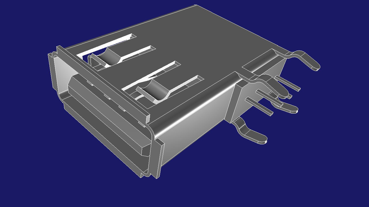
The initial model with faces and edges.
In our data, the scene graph structure is somewhat complex:
- We have one
RED::IMeshShapeobject instance for each face in the part- We have one
RED::ILineShapeobject instance for the edges of each face in the part
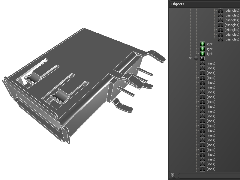
The initial scene structure.
There are approximatively 2000 triangles split into more than 500 objects: this is obviously too much. HOOPS Luminate has a “heavy” scene graph with many attributes owned by each shape instance (matrices, materials, layersets, …); therefore using too many shapes for too few triangles is not optimal at all.
Merging Faces and Edges
Consequently, to optimize the performance of the display of our entities as well as to reduce the memory footprint of our model, we have to merge all faces of a part together. Similarly, we’ll group all edges of a part together into a single larger shape.
But, we need a way to remain flexible: we need to keep the capability to select and highlight each individual face in our part, even after the merge. This can be achieved using the RED::RenderShaderViewport. This shader has a few special features that make it very attractive in interactive environments that need good edition performances:
- It’s a single pass shader with an integrated lighting (it displays geometries as fast as possible)
- It uses a per vertex colour channel to define the colour of all geometries (it can display for example FEM heat results or colour faces separately)
- Highlighting is integrated using the alpha value of the vertices colour (changing the colour of all vertices of a face will highlight that face)
Therefore, the highlighting operation of a face becomes a colour edition of all vertices of a face. This is a fast and optimized operation that only changes a small memory block in the video memory of the scene (this is a smart GPU update, see Modifying Engine Data for details).
The step 2 of the tutorial merges all faces of the part in a single mesh shape, and does the same for edges.
Now that all faces are merged together in a single shape, we still want to highlight our initial faces separately. This is achieved by keeping some information that were collected during the merge process:
- We store the vertex boundaries for each face: the i-th face starts at vertex no xxx and ends at vertex no yyy
- We store the triangle boundaries for each face: the i-th face starts at triangle no ttt and ends at triangle no uuu
Then, during the highlight procedure, we can retrieve the picked face from the RED::ShapePath picking information and access to the original face data in our global mesh. We do this by storing a RED::UserData container on the shape.
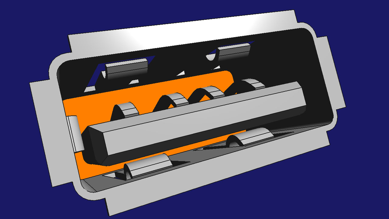
The scene with a highlighted mesh.

