Writing a Custom Rendering Shader in GLSL
This tutorial is an example of custom render shader creation writing vertex and pixel programs in GLSL. It is divided into three steps:
- Writing an ambient shader
- Writing a phong shader
- Writing a phong shader using a diffuse texture
Writing a GLSL Shader with HOOPS Luminate
Loading Shader
There’s no difference between loading an ARB shader program and a GLSL program: the RED::IResourceManager::LoadShaderFromString method must be used for both kind of programs.
The engine automatically detects the kind of shader it receives, based on the standard headers that all versions of ARB shaders must enforce (!!ARBfp1.0 for a GL_fragment_program_ARB compatible program for example). A shader that doesn’t start with an ARB header is considered as being a GLSL shader.
Because GLSL is a high level programming language, the RED::ShaderString is not needed.
Here is the loading of our ambient shader:
// b. A vertex shader in GLSL:
RC_TEST( LoadShaderProgram( program, "../Resources/WritingCustomGLSLShader_ambient_vsh.txt" ) );
RC_TEST( iresmgr->LoadShaderFromString( shaderID, program ) );
RC_TEST( ambient.SetVertexProgramId( shaderID, RED_L0, resmgr ) );

// c. A pixel shader in GLSL:
RC_TEST( LoadShaderProgram( program, "../Resources/WritingCustomGLSLShader_ambient_psh.txt" ) );
RC_TEST( iresmgr->LoadShaderFromString( shaderID, program ) );
RC_TEST( ambient.SetPixelProgramId( shaderID, RED_L0, resmgr ) );
‘LoadShaderProgram’ is a tutorial function which simply gets a RED::String from an external file.
Binding Vertex Shader Inputs
Vertex shader inputs are bound using the RED::RenderCode mechanism. The following table shows the correspondence between RED::RenderCode channels and standard GLSL vertex shader inputs:
| Vertex Channel | GLSL Inputs |
|---|---|
RED_VSH_VERTEX |
gl_Vertex |
RED_VSH_NORMAL |
gl_Normal |
RED_VSH_COLOR |
gl_Color |
RED_VSH_TEX0 to RED_VSH_TEX7 |
gl_MultiTexCoord0 to gl_MultiTexCoord7 |
The ambient shader only needs vertex position:
// a. Geometrical shader input:
RED::RenderCode rcode;
rcode.BindChannel( RED_VSH_VERTEX, RED::MCL_VERTEX );
RC_TEST( ambient.SetRenderCode( rcode, RED_L0 ) );
Binding Parameters
GLSL uniforms are bound using regular RED::RenderShaderParameter instances, added as parameters to the considered shader. The corresponding types are:
| Parameter Type | GLSL Type |
|---|---|
RED::RenderShaderParameter::VECTOR |
vec4 |
RED::RenderShaderParameter::VECTOR3 |
vec3 |
RED::RenderShaderParameter::COLOR |
vec4 |
RED::RenderShaderParameter::FLOAT |
float |
RED::RenderShaderParameter::BOOL |
bool |
RED::RenderShaderParameter::TEXTURE |
sampler1D, sampler2D, sampler2DRect, samplerCube |
RED::RenderShaderParameter::MATRIX |
mat4 |
For instance, the parameters sent to the ambient shaders are:
// d. Some shader parameters:
RED::RenderShaderParameter light_ambient( "light_ambient", 0, RED::RenderShaderParameter::PSH );
light_ambient.SetReference( RED::RenderShaderParameter::REF_LIGHT_AMBIENT );
RC_TEST( ambient.AddParameter( light_ambient, RED_L0 ) );

RED::RenderShaderParameter object_color( "object_color", 0, RED::RenderShaderParameter::PSH );
object_color.SetValue( g_torus_color );
RC_TEST( ambient.AddParameter( object_color, RED_L0 ) );
Note
Binding positions are ignored for all kind of GLSL parameters but for textures, for which we must select a texture unit that is used to receive the texture before its name can be used to properly bind it.
Writing GLSL Ambient Shader
The ambient shader is one of the simplest render shader. It only applies the object color modulated by the ambient light color.
The vertex shader only does its primary task: transforming the vertex position:
void main(void)
{
    gl_Position = gl_ModelViewProjectionMatrix * gl_Vertex;
}
The pixel shader outputs the color:
uniform vec4 light_ambient;
uniform vec4 object_color;

void main(void)
{
    gl_FragColor = light_ambient * object_color;
    gl_FragColor.a = 1.0;
}
We can see in this code sample that the two RED::RenderShaderParameter defined previously are available in the GLSL program as uniform variables.
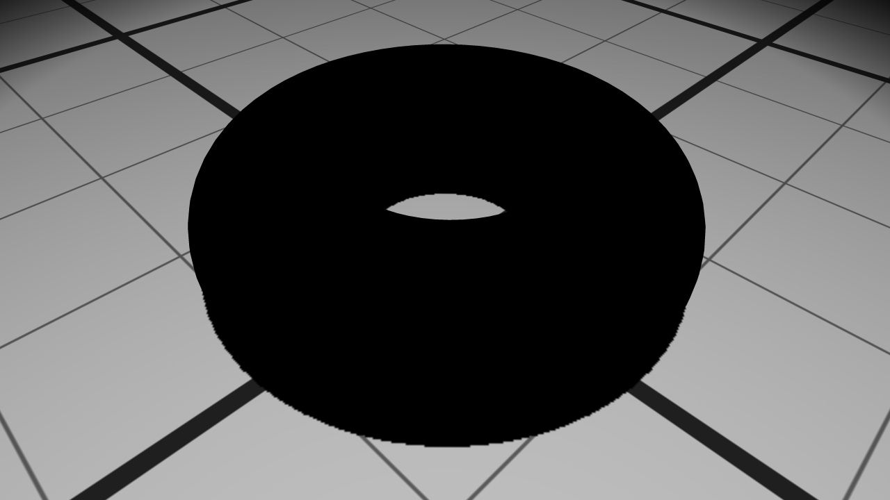
The material after ambient shading
The object appears black despite its color because there is no ambient light color in our scene.
A Word on GLSL Matrix Transforms
For the purpose of this example we have used the modelview-projection matrix accessible by default to GLSL programs as the ‘gl_ModelViewProjectionMatrix’ string. This matrix has a high definition equivalent value accessible in ‘gl_TextureMatrix[2]’, as detailed by RED::RenderCode::SetModelViewProjectionMatrix. The matrix bound by the RED::RenderCode is suitable to solve floating origin issues (see Floating Origins) unlike the default OpenGL matrix.
The same matrix also exists for the modelview (RED::RenderCode::SetModelViewMatrix) or for the view matrix (RED::RenderCode::SetViewMatrix).
Writing GLSL Phong Shader
In a second step, a Phong shader is created and added to the object material. Phong shading will add diffuse and specular colors to the existing ambient one. The Phong lighting calculation is done in the pixel shader because it needs interpolated normals and positions.
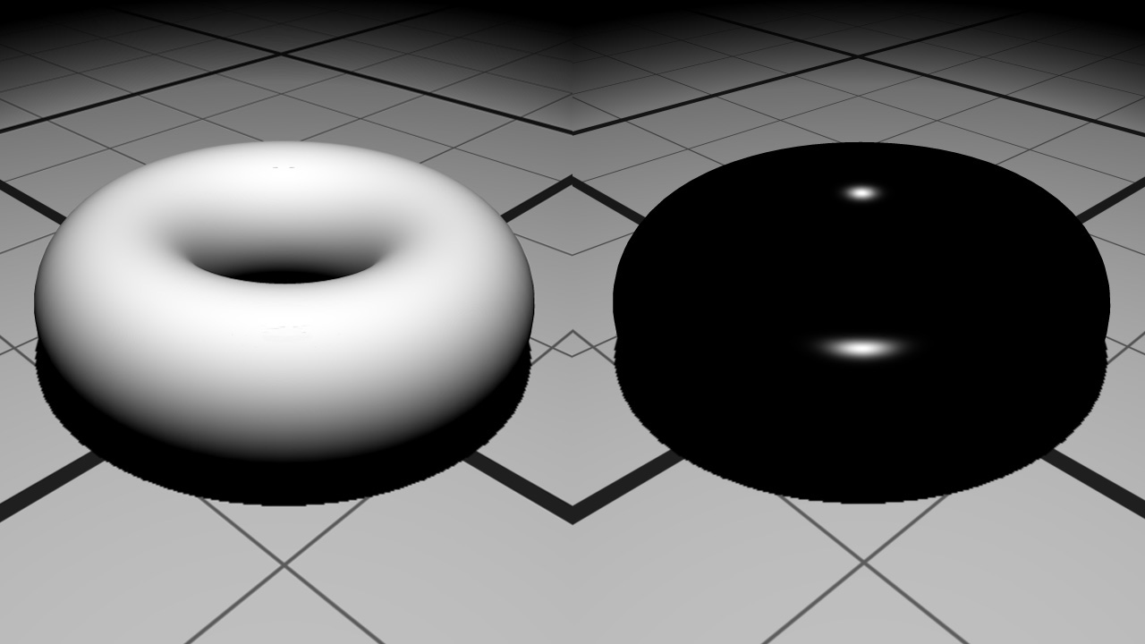
Diffuse color on the left and specular color on the right
The positions and normals have to be transmitted from the geometry to the pixel shader. First the RED::RenderCode will bind them:
// a. Geometrical shader input:
RED::RenderCode rcode;
rcode.BindChannel( RED_VSH_VERTEX, RED::MCL_VERTEX );
rcode.BindChannel( RED_VSH_NORMAL, RED::MCL_NORMAL );
rcode.SetModelMatrix( true );
RC_TEST( phong.SetRenderCode( rcode, RED_LS ) );
In the vertex shader, they are accessed through the gl_Vertex and gl_Normal GLSL variables and sent to the next pipeline stage using the output structure:
// The vertex shader output:
out VertexData
{
    vec3 vPosition;
    vec3 vNormal;

} vertex_out;

void main()
{
    // Transform vertex from object space to clip space:
    gl_Position = gl_ModelViewProjectionMatrix * gl_Vertex;

    // Transform position from object space to world space
    // and transfer it to the next stage:
    // gl_TextureMatrix[1] contains the world matrix.
    vec4 pos = gl_TextureMatrix[1] * gl_Vertex;
    vertex_out.vPosition = pos.xyz;

    // Transform normal from object space to world space
    // and transfer it to the next stage:
    vec4 nor = gl_TextureMatrixInverseTranspose[1] * vec4( gl_Normal.xyz, 1.0 );
    vertex_out.vNormal = nor.xyz;
}
The data are transformed from object space to world space. To do this, the program needs the world matrix. It is transmitted through the gl_TextureMatrix[1] variable because we called the RED::RenderCode::SetModelMatrix function during the shader creation phase.
The pixel shader contains all the phong shading calculations. It receives the interpolated normals and positions thanks to its input structure and several parameters as uniform variables.
uniform vec4 lightPos;
uniform vec4 lightColor;
uniform vec4 objectColor;
uniform vec4 eyePos;

uniform sampler2DRect lightShadow;

in VertexData
{
    vec3 vPosition;
    vec3 vNormal;

} vertex_in;

void main()
{
    // Phong lighting:
    vec3 light   = normalize( vec3( lightPos ) - vertex_in.vPosition );
    vec3 normal  = normalize( vertex_in.vNormal );
    vec3 eye     = normalize( vec3( eyePos ) - vertex_in.vPosition );
    vec3 reflect = 2.0 * clamp( dot( normal, light ), 0.0, 1.0 ) * normal - light;

    float diffuse = clamp( dot( light, normal ), 0.0, 1.0 );
    float specular = pow( clamp( dot( reflect, eye ), 0.0, 1.0 ), 60.0 );
    float shadow = texture2DRect( lightShadow, vec2( gl_FragCoord ) ).x;

    gl_FragColor = objectColor * lightColor * ( diffuse + specular ) * shadow;
    gl_FragColor.w = 1.0;
}
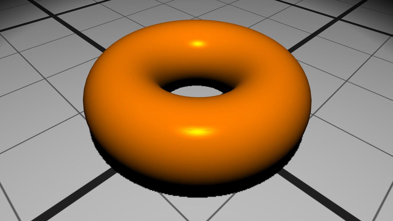
The material after Phong shading
Writing GLSL Textured Phong Shader
During the last step of the tutorial, we will see how to replace the object color by a texture image. To correctly apply a texture on an object, a shader program needs texture coordinates. Our object has texture coordinates contained in the RED::MCL_TEX0 geometry channel.
Note
In case your object does not have texture coordinates, HOOPS Luminate provides a useful function to build them: RED::IMeshShape::BuildTextureCoordinates.
Like the vertex and normal channels, the texture coordinates channel needs to be bound in the RED::RenderCode object:
rcode.BindChannel( RED_VSH_TEX0, RED::MCL_TEX0 );
The data is then retrieved in the vertex shader using the gl_MultiTexCoord0 variable and transmitted to the pixel shader via the output structure:
// Transfer the texture coordinates to the next stage:
vertex_out.vTexCoord = gl_MultiTexCoord0.xy;
The pixel shader gets the texture image using a uniform sampler2D shader parameter and samples it using the texture coordinates:
vec4 objectColor = texture2D( diffuseTexture, vertex_in.vTexCoord * textureScale );
A scale is also transmitted as a uniform parameter to adjust the size of the texture on the object.
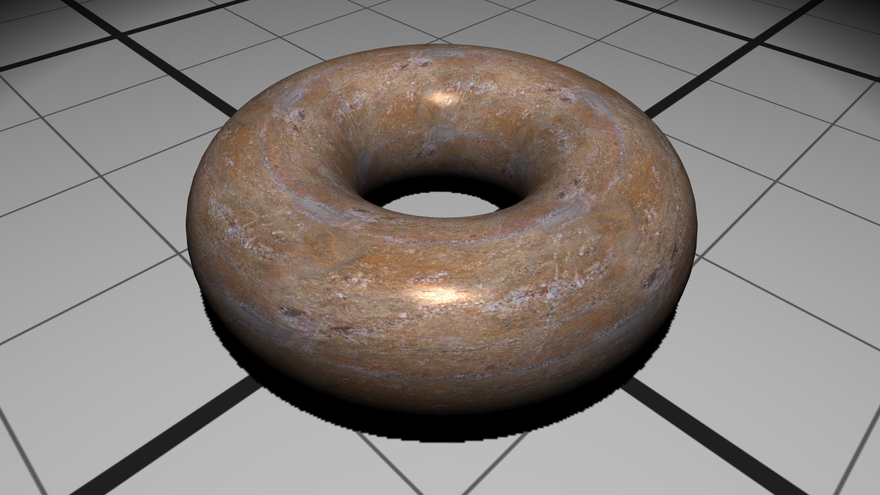
The material after textured Phong shading

