Adding Edges
This simple tutorial illustrates HOOPS Luminate built-in method to create edges from a source geometry. We start with three simple cylinders and add edges to each of them. This produces the result below:
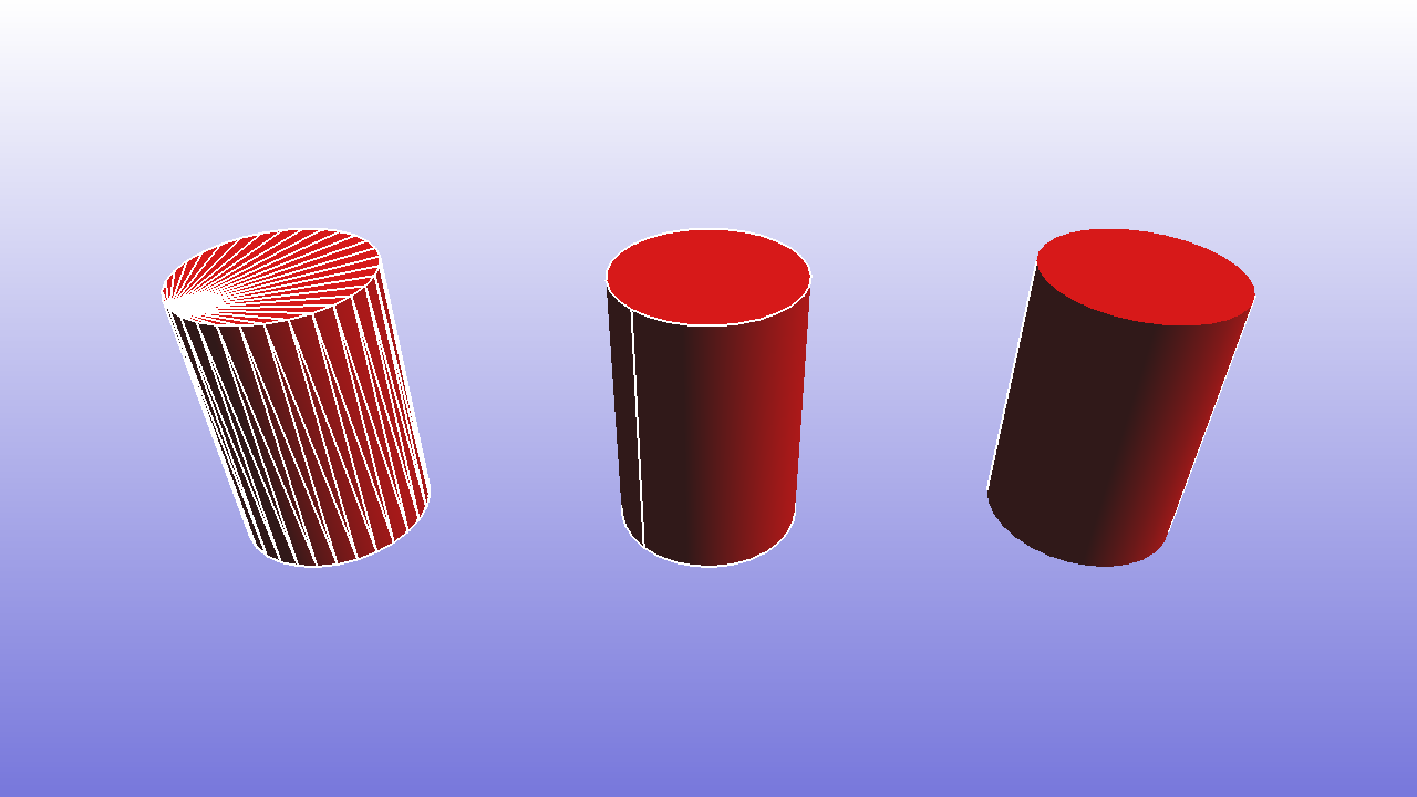
Inner edges to the left, border edges in the middle, contour edges on the right.
Inner, Border and Contour (Silhouette) Edges
By definition we call the edge of a mesh any line segment joining two vertices in a triangle of that mesh. Then, we make three useful classifications among edges:
- An inner edge of a mesh geometry is an edge which is shared by two triangles at least (may be three or more if we have non-manifold topologies)
- A border edge of a mesh geometry is an edge which belongs to one single triangle
- A contour edge is an inner edge whose two adjacent triangles have opposite facing to the camera
This is summarized below:
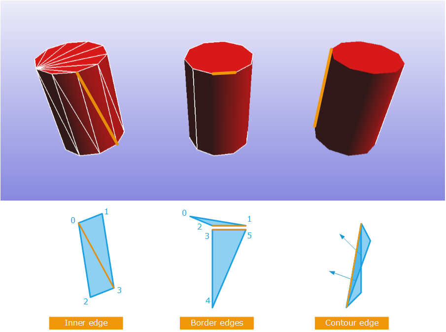
Edge classification in HOOPS Luminate
The inner edge has two adjacent triangles. In the example above, these are (013) and (023). If one of the triangles has a normal that is looking backward from the camera AND the other triangle looking forward to the camera, then we call this a contour edge. It’s a silhouette edge.
Finally, a border edge has only one adjacent triangles; Very often, we have two overlapping border edges in a solid made of faces. The cylinder cap border overlaps the cylinder body border, so we have one border edge for the triangle (012) and another one for the triangle (345) with different vertices that result of the different shadings (the top cylinder cap has vertex normals oriented toward +z while cylinder body vertex normals are turning aroung in the xy plane).
Note that on the cylinder we have a border on the body at the point where cylinder UVs are wrapping. That’s why there’s a border. If we had no UVs, then we could remove that border.
Edge Creation
Finally, the edge creation code is very small: For each configuration, one of the edges creation methods available from the RED::IMeshShape interface is used:
RED::IMeshShape::BuildEdgesto construct all edges in a meshRED::IMeshShape::BuildBorderEdgesto construct only border edges in a meshRED::IMeshShape::BuildContourEdgesto construct all three types of edges, with the possibility to visualize each separately or together
Contour edges require using the RED::RenderShaderEdges. The specified data channels used by the shader are the same as those used during the construction of contour edges:
RC_TEST( immesh->BuildContourEdges( line, RED::MCL_VERTEX, RED::MCL_USER0, RED::MCL_USER1, RED::MCL_VERTEX, iresmgr->GetState() ) );
And for the shading part:
RED_RC CreateContourMaterial( RED::Object*&     matr,
                            const RED::Color& color )
{
    RED::Object* resmgr = RFK::TutorialApplication::GetResourceManager();
    RED::IResourceManager* iresmgr = resmgr->As< RED::IResourceManager >();

    RC_TEST( iresmgr->CreateMaterial( matr, iresmgr->GetState() ) );
    RED::IMaterial* imatr = matr->As< RED::IMaterial >();

    RED::StateShader ssh;
    RC_TEST( ssh.SetLineWidth( 2.0f ) );

    RC_TEST( imatr->RegisterShader( ssh, iresmgr->GetState() ) );
    RC_TEST( imatr->AddShaderToPass( ssh.GetID(), RED::MTL_PRELIT, RED::LIST_LAST, RED::LayerSet::ALL_LAYERS, iresmgr->GetState() ) );

    RED_RC rc;

    RED::RenderShaderEdges esh( RED::MTL_PRELIT,
                                RED::MCL_VERTEX,
                                RED::MCL_USER0,
                                RED::MCL_USER1,
                                color,
                                false,
                                true,
                                RED_PI,
                                resmgr,
                                rc );

    RC_TEST( imatr->RegisterShader( esh, iresmgr->GetState() ) );
    RC_TEST( imatr->AddShaderToPass( esh.GetID(), RED::MTL_PRELIT, RED::LIST_LAST, RED::LayerSet::ALL_LAYERS, iresmgr->GetState() ) );

    return RED_OK;
}

