Manipulating Images
For any graphics middleware, images are vital resources, both in inputs and outputs. This chapter covers some of the API and usages of images in HOOPS Luminate. You’ll learn how you can dynamically edit images content and use the images in your own materials and shaders.
Synchronous Model
Contrary to other resources in RED, images are managed synchronously with the rendering. It means that whatever the image operation is, it breaks any currently running rendering process. Hence, all your image operations must take place between rendering orders (if you don’t want to interrupt the rendering; otherwise you don’t care), from the rendering thread.
You can learn more about why images are processed differently from other HOOPS Luminate resources by reading: Modifying Images During a Draw
Managing Image Pixels
The pixels of a HOOPS Luminate image can be stored in main memory, graphics card memory or both depending on the rendering mode (software, hardware or hybrid). However, no matter the location of the images is, you can’t access to their contents directly and first need to “download” the pixels into the image local storages (see RED::IImage2D::GetPixels and RED::IImage3D::GetPixels) which are also located in main memory.
Some images can internally exist in up to two versions. In that case, depending on the image type, the retrieved content comes from the software or from the hardware version of the image. For example, if the engine is running in hybrid mode and the image is a 2d texture (RED::TGT_TEX_2D or RED::TGT_TEX_RECT), the RED::IImage2D::GetPixels method will return the pixels from the software version of the texture (which may be different from the hardware version of the image due to hardware limitations (in size for example)). The rule is that for any image which exists in both software and hardware versions, this is always the software version which is returned by the access methods.
As soon as the image content has been downloaded to the local storage, you can get access to it by calling the methods from the RED::IImage2D and RED::IImage3D interfaces prefixed by Get/SetLocalXXX (for example, RED::IImage2D::SetLocalPixels sets the pixels of a 2d image in the local storage). Working in the local storage has the advantage it can be done in parallel of any rendering operation (Modifying Images During a Draw).
Once your modifications have been applied to the image in the local storage, they need to be committed to the engine in order to be used in the next rendering operation. This is achieved by calling RED::IImage2D::SetPixels or RED::IImage3D::SetPixels. Those methods upload the content of the local storage to the current renderer(s) memory and must be called out of any rendering operation.
Note
A natural workflow for image edition would then be to edit the images locally (in their local storage) in parallel of the rendering (using multi-threading for example) and to commit the changes to the renderer at fixed synchronization points on the main rendering thread between two rendering operations.
Using Images as Textures
Images are often used as textures to add details to geometries without having to model everything. The way textures are projected onto geometries is described by texture coordinates. Those are geometry channel data (one texture coordinates vector per geometry vertex, see Mesh Shapes) and are used to compute the correspondence between a point at the surface of the geometry and a texel in the texture.
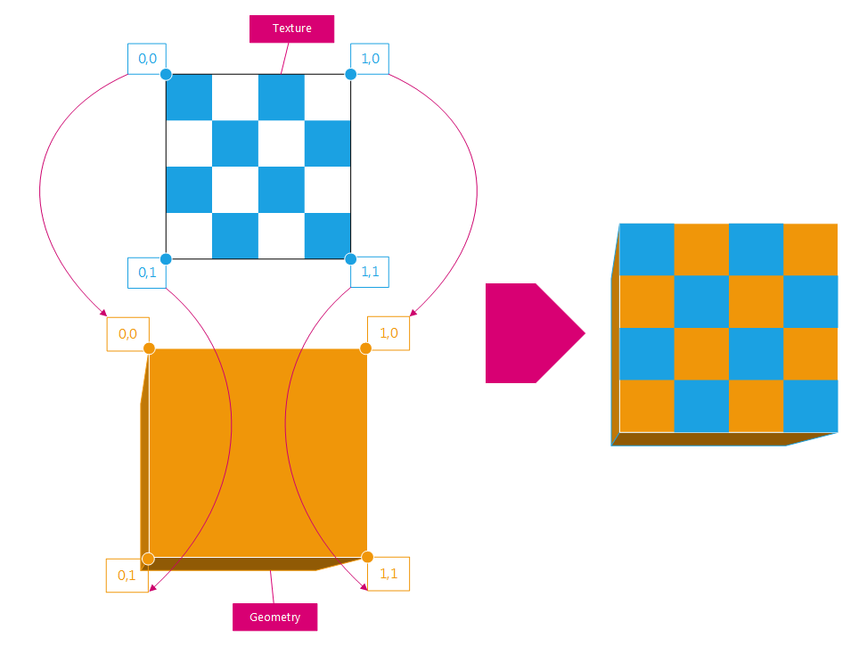
Each texel in the texture is mapped to a given position onto the geometry. The correspondence between the two is given by the geometry texture coordinates channel (in orange on the figure).
Just by modifying the geometry texture coordinates, one can get really different mappings of the same texture:
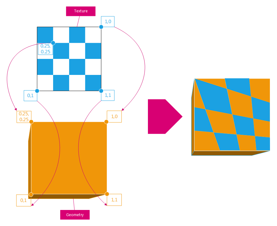
Same as above, but the geometry texture coordinates have been changed a little bit.
Wrap Modes
The texture coordinates are most of the time defined in the [0,1]x[0,1] interval. However, transformation matrices can be applied to the geometry texture coordinates in order to produce more different mappings. Hence using translation, scaling and rotation, you can dynamically transform the existing geometry texture coordinates. Applying such transformations can transform the geometry texture coordinates to any floating point value (including negative or out-of-texture ones). To solve those cases, the engine applies warping operations to the transformed texture coordinates (RED::IImage::SetWrapModes). A RED::WRAP_MODE can be defined for each texture dimension and tells the engine how corresponding texture coordinates should be handled when out of the [0,1] interval.
Here is a figure that summarizes the effect of the various wrap modes of HOOPS Luminate when applied identically to each dimension:
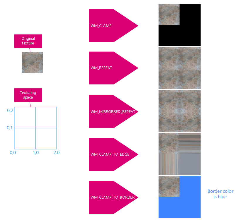
Effect of the wrap modes when mapping a texture to the [0,2]x[0,2] interval.
The border colour used in the RED::WM_CLAMP_TO_BORDER wrap mode can be set with RED::IImage::SetBorderColor.
Filter Modes
When a texture is stretched over a large surface, the texels start to be visible and blocking artefacts can occur. HOOPS Luminate provides two filter modes that can be applied to textures (RED::FILTER_MODE):
RED::FM_NEAREST: no filtering; nearest texel is used when mapping the textureRED::FM_LINEAR: bilinear filtering of the texels
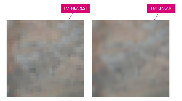
The image filtering modes available in HOOPS Luminate.
Mipmapping
When textures are projected onto a very small surface or seen from a big distance, they can appear as noisy if there are too many details in it. Mipmapping provides a decent solution to this problem and is seamlessly supported by the graphics cards.
Mipmapping can be enabled per texture in HOOPS Luminate (RED::IImage::SetMipmapMode). When on, scaled down filtered versions of the original image are pre-computed and stored: they form the mipmap levels of the image. At render time, the appropriate mipmap level of an image is selected based of the texel coverage of the rendered pixel. Mipmaps cost approximatively 33% more memory than the original texture alone.
Note
In HOOPS Luminate, mipmapping is only available with hardware rendering.
Bump and Normal Mapping
HOOPS Luminate supports normal mapping which is a trick to simulate small geometric details over a surface by using a texture.
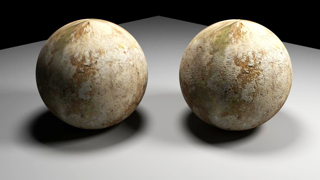
The effect of normal mapping over a sphere (without on the left, with on the right).
Normal mapping uses dedicated textures where the RGB components store the explicit transform to apply to the geometry normal in x, y and z directions. Those textures differ from the bump maps which are classical RGB maps.
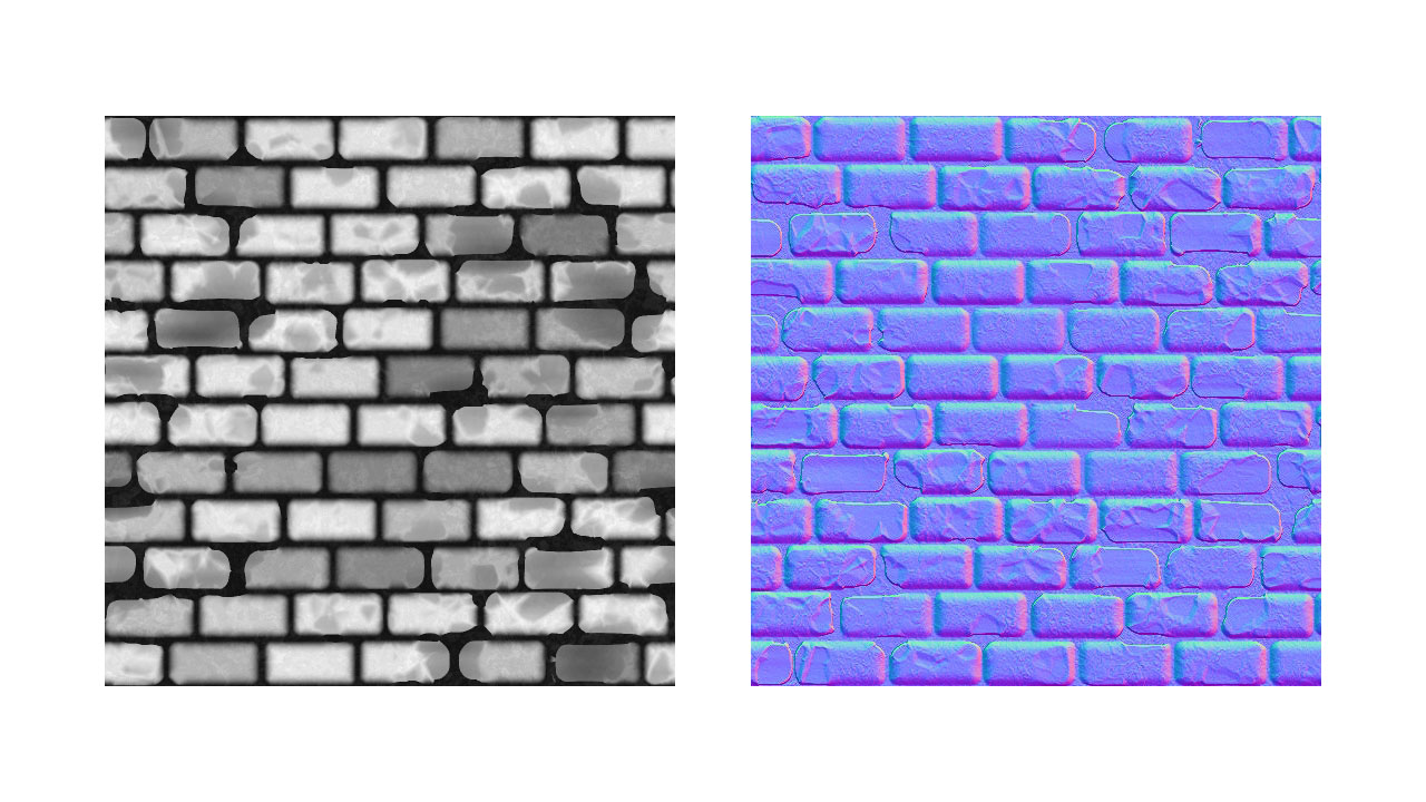
The differences between a bump map (on the left) and a normal map (on the right).
If your input texture is a bump one, you need to transform it into a normal map before setting it in RED. This is easily accomplished by using the RED::IImage2D::NormalMap method.
Creating a Bump Map from Any Image
HOOPS Luminate implements bump mapping through the support of normal maps. To convert any bump map to a normal map, simply do:
RED::Object* image2d;
RC_TEST( iresmgr->CreateImage2D( image2d, iresmgr->GetState() ) );
RC_TEST( RED::ImageTools::Load( image2d, "./my_bump_map.hdr", RED::FMT_RGB, false, false, RED::TGT_TEX_2D, iresmgr->GetState() ) );

RED::IImage2D* i2d = image2d->As< RED::IImage2D >();
RC_TEST( i2d->NormalMap( RED::FMT_RGB, RED::TGT_TEX_2D, 3.f, image2d, iresmgr->GetState() ) );
Note
When using normal maps, the texture coordinates channel of the destination mesh is not enough any more. To compute the effect of the normal mapping, RED needs to build back a local orthogonal basis to the shading point and the normal vector alone is not sufficient. It needs additional vectors called the tangents vectors. Those vectors can be built automatically by calling RED::IMeshShape::BuildTangents (see Hello World! for an example).
Note
Don’t be confused; normal mapping and displacement mapping (both supported in HOOPS Luminate) are two very different approximations to the same effect: they both try to add details to geometries through textures. But, while bump mapping modifies the normal used to shade the surfaces, displacement mapping actually modifies the geometries themselves for a better result (and longer rendering times). Learn more on displacement mapping here: Setup Geometries in the section Using Displacement Mapping.

