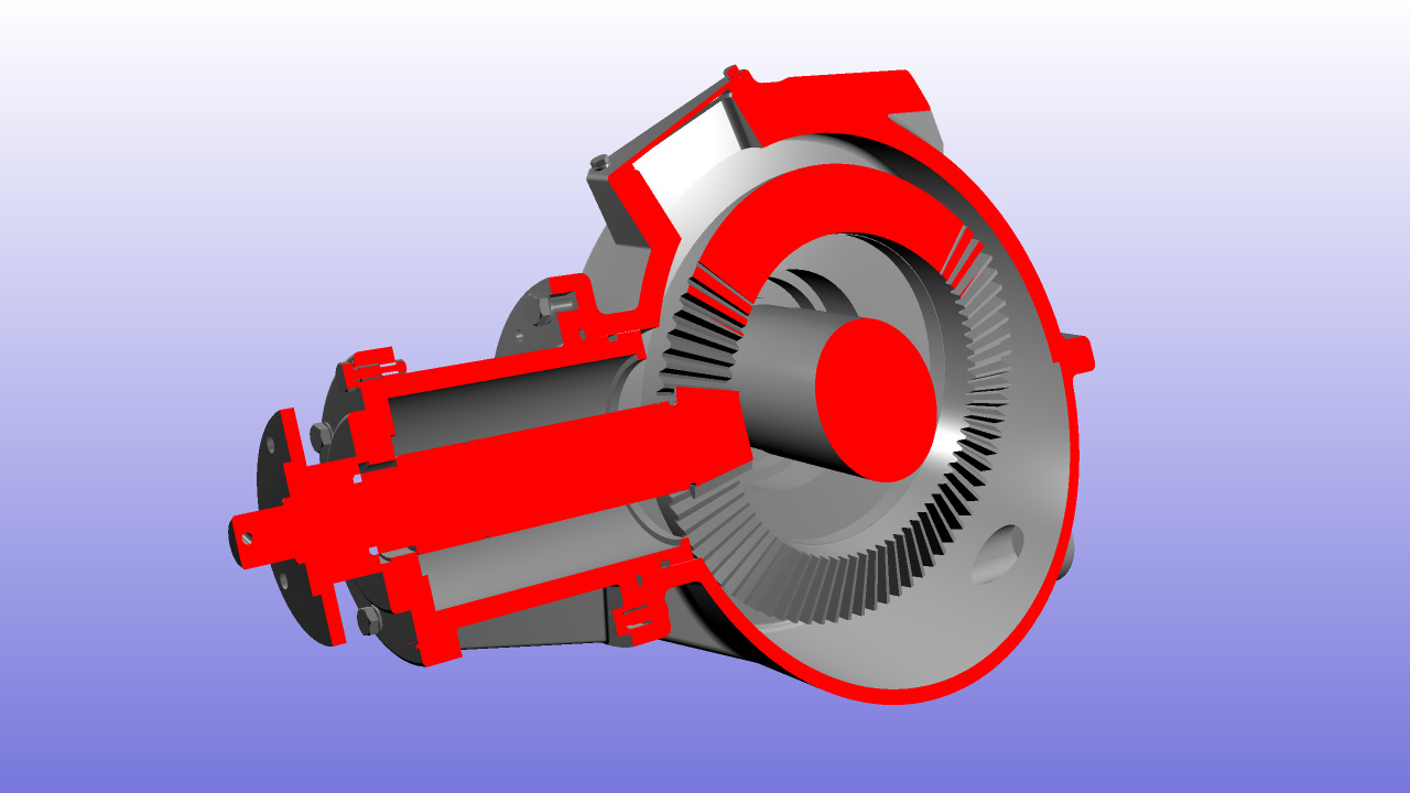
Cutting Geometries: A Practical Example
The aim of this tutorial is to show how to correctly setup a section cutting plane and use it to slice a geometry.
Section cutting
Plane Definition
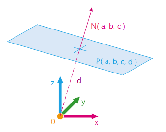
Mathematically, a plane P can be defined by its equation:
- ax + by + cz + d = 0
It is called the general form of the equation of the plane.
The vector formed by the first coefficients N (a, b, c) is a normal to the plane.
If N is normalized then the d coefficient is the plane distance from world origin O.
Plane equation
Section Cutting Functions
HOOPS Luminate allows to define a section cutting plane and slice a geometry with it. This is done via the material function RED::IMaterial::SetCuttingPlane.
Its input parameters are:
- The plane equation as an array of four coefficients
- A
RED::RenderShaderto fill the cut section. If NULL then the cut section is not rendered- The layerset for which the setup is done
All the geometry parts on the positive side of the plane are not rendered. If a cap shader is provided, it is used to fill the geometry holes created by the cutting plane.
// Setting the material to the shape:
RED::IShape* ishape = torus->As< RED::IShape >();
RC_TEST( ishape->SetMaterial( mat, state ) );

// Define the plane equation A*x + B*y + C*z + D = 0.
// A plane is defined by its normal (A, B, C) and its distance from origin D.
float plane_eq[4] = { (float)g_plane_normal[0], (float)g_plane_normal[1], (float)g_plane_normal[2], (float)g_plane_distance };

// Create a solid shader for the cutting section:
RED::RenderShaderSolid solid( RED::MTL_POSTLIT,
                            RED::Color::RED, NULL, RED::Matrix::IDENTITY, RED::MCL_TEX0,
                            RED::Color::WHITE, NULL, RED::Matrix::IDENTITY, RED::MCL_TEX0,
                            resmgr, rc );
RC_TEST( rc );

// Set the cutting plane to the mesh material:
RC_TEST( imat->SetCuttingPlane( plane_eq, &solid, RED::LayerSet::ALL_LAYERS, false, state ) );
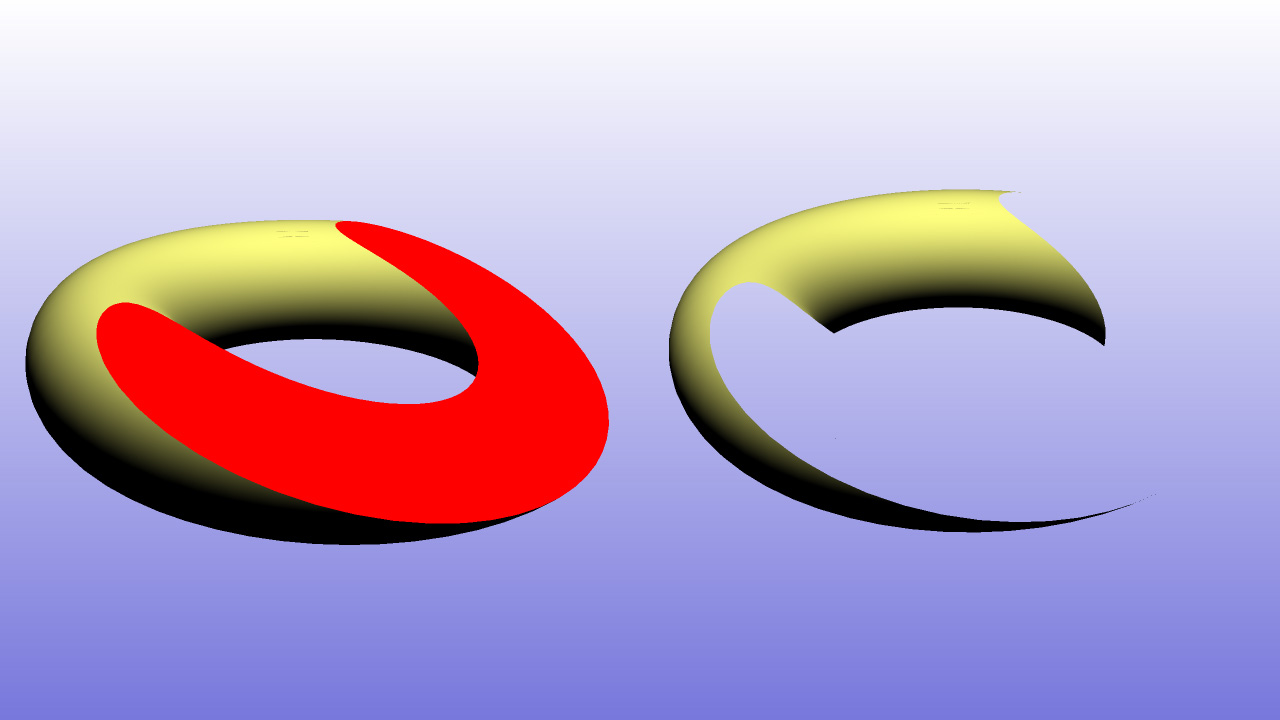
Section cutting with and without cap shader
Once a cutting plane has been defined with the RED::IMaterial::SetCuttingPlane method, HOOPS Luminate permits to easily update the plane equation with a second method named RED::IMaterial::UpdateCuttingPlaneEquation.
It takes as input:
- The new plane equation as a four values array
- The layerset for which the setup is done
// Get the resource manager:
RED::Object* resmgr = RFK::TutorialApplication::GetResourceManager();
RED::IResourceManager* iresmgr = resmgr->As< RED::IResourceManager >();

// Compute the new plane equation according to the rotation and offset:
RED::Vector3 new_normal = g_plane_rotation.RotateNormalize( g_plane_normal );
float plane_eq[4] = { (float)new_normal[0], (float)new_normal[1], (float)new_normal[2], g_plane_distance + g_plane_offset };

// Update the cutting plane section with the new equation:
RC_TEST( g_imaterial->UpdateCuttingPlaneEquation( plane_eq, RED::LayerSet::ALL_LAYERS, iresmgr->GetState() ) );
Here, we rotate the plane with a rotation RED::Matrix and translate it with a distance offset. The new plane equation is finally sent to the material with RED::IMaterial::UpdateCuttingPlaneEquation.
Section Cutting on an Incorrect Geometry
If the given geometry contains overlapping parts or incorrect intersections, some artefacts could appear in the cut section visualization. As an example, you can see the incorrect part in the following image of two intersected tori:
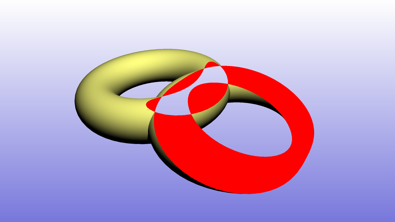
Section cutting with incorrect geometry
To avoid this kind of errors, users must ensure that the provided meshes are clean and don’t contain such bad intersections or overlapping parts.

