Materials and Lighting
Materials for 2D Shading
The RedOdaDevice uses special shaders for the sole purpose of shading and highlighting primitives using customizable selection patterns. Practically, the full set of functions is embedded into a single shader: coloring the geometry and selecting it.
Line Material in 2D
The line material is a good example to illustrate how these drafting materials used in the device are made. We’ll focus on the source code of the shader programs it uses:
// Line material - render shader - rendercode:
// -------------------------------------------

RED::RenderCode rcode;
rcode.BindChannel( RED_VSH_VERTEX, RED::MCL_VERTEX );
rcode.BindChannel( RED_VSH_COLOR, RED::MCL_COLOR );
rcode.BindChannel( RED_VSH_TEX0, RED::MCL_TEX0 );
rcode.SetNormalizedChannel( RED_VSH_COLOR );

if( _is_custom_depth == true )
    rcode.BindChannel( RED_VSH_USER0, RED::MCL_USER0 );
The RED::RenderCode bridges the geometry data at the shader entrance: the vertex shader stage of the pipeline. Here, we bind several geometrical attributes of the line vertices:
RED::MCL_VERTEX: This is the input position ( x, y, z ) of the line vertex.
RED::MCL_COLOR: This is the color of that vertex ( r, g, b, a ). We need a normalized color.
RED::MCL_TEX0: This is a special data channel added for highlighting purposes. This stores the parametric length of the polyline being drawn from it’s first vertex up to this one. This length is stored in model units. It’s defined inside ROD::OdBatch::AddLineEntity.
RED::MCL_USER0: This is the custom depth of the primitive. e.g. this is it’s draw order as defined by the playMetafile call.
Let’s detail the parametric length parameter: Our purpose is to be able to select a line by replacing it’s filled pattern by a 50% dashed pattern, as illustrated by the picture below:
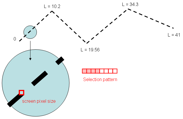
Example of a line selection using a 8 pixel long pattern.
We store the total length of the line, starting from its first vertex down to its last vertex in the RED::MCL_TEX0 channel of the line. In our example, We have a cumulated length along the line of 0, 10.2, 19.56, 34.3 and 41: This means that the total length of the polyline is 41 model units.
Then, from this, the vertex shader calculates the size of a pixel projected back onto the vertex geometry. This size is sent in ‘result.texcoord[1]’ to the pixel shader that’ll apply the selection pattern texture.
// Line material - render shader - vertex shader:
// ----------------------------------------------
//  o Inputs: vertex.attrib[0]: Vertex position.
//            vertex.attrib[1]: Vertex depth (optional).
//            vertex.attrib[3]: Vertex color.
//            vertex.attrib[8]: Total length along the line since it's first vertex.
//            program.local[0]: REF_VRL_DIMENSIONS.
//
//  o Outputs: result.color.primary: Vertex color.
//             result.texcoord[0]: Interpolated length at our screen pixel
//             result.texcoord[1]: 1 / Model size of a screen pixel.
//             result.texcoord[2]: Vertex depth (optional).

RED::ShaderProgramID vshid;
RED::ShaderString vsh;

vsh.VertexShaderStart();

// Sending the vertex color of that line segment:
vsh.Add( "MOV result.color.primary, vertex.attrib[3];\n" );

// Sending the length along our contiguous line segments:
vsh.Add( "MOV result.texcoord[0], vertex.attrib[8];\n" );

// Calculating the size of a screen pixel backwards in model units: we
// convert back a vector of the height equal to one pixel (note that the
// matrix.mvp is normalized and does not contain the viewporting matrix, so
// the boudaries of the visible space are [-1,1] x [-1,1], hence the 2 in
// determining the length of a vector.
vsh.Temp( "pix" );
vsh.Temp( "p0" );
vsh.Temp( "p1" );
vsh.Temp( "p01" );

vsh.VertexTransform( "p0", "state.matrix.mvp.inverse", "{ 0, 0, 0, 1 }" );
vsh.Add( "MOV pix, { 0, 2, 0, 1 };\n" );
vsh.Add( "MUL pix.y, pix.y, program.local[0].y;\n" );
vsh.VertexTransform( "p1", "state.matrix.mvp.inverse", "pix" );
vsh.Add( "ADD p01, p0, -p1;\n" );
vsh.Add( "DP3 p01.w, p01, p01;\n" );
vsh.Add( "RSQ p01.w, p01.w;\n" );
vsh.Add( "MOV result.texcoord[1], p01.w;\n" );

// Sending the vertex custom depth (optional):
if( _is_custom_depth == true )
    vsh.Add( "MOV result.texcoord[2], vertex.attrib[1];\n" );

// Calculating the output device vertex coordinates:
vsh.VertexTransform( "result.position", "state.matrix.mvp", "vertex.attrib[0]" );

vsh.ShaderEnd();

RC_RETURN( iresmgr->LoadShaderFromString( vshid, vsh ) );
To calculate the size of a camera pixel “seen” onto the geometry, we calculate the length of a small [p0,p1] vector, which is 1 pixel high projected backwards on the geometry. This length corresponds to the “model size of screen pixel”:
p0 matches the screen pixel ( 0, 0 ).
p1 matches the screen pixel ( 0, 1 ). If our window height is ‘h’, then the pixel coordinate of p1 is ( 0, 2 / h ), considering that our matrices are defined for a normalized [ -1, 1 ] x [ -1, 1 ] viewport.
Then, in the pixel shader:
// Line material - render shader - pixel shader:
// ---------------------------------------------
//  o Inputs: fragment.color.primary: Vertex color.
//            fragment.texcoord[0]: Interpolated length at our screen pixel
//            fragment.texcoord[1]: 1 / Model size of a screen pixel.
//            fragment.texcoord[2]: Vertex depth (optional).

RED::ShaderProgramID pshid;
RED::ShaderString psh;

psh.PixelShaderStart();

psh.Temp( "length" );
psh.Temp( "select" );
psh.Temp( "color" );
psh.Temp( "R0" );
psh.Add( "MUL length, fragment.texcoord[0].x, fragment.texcoord[1].x;\n" );
psh.Add( "MUL length, length, { 0.03125 }.x;\n" );
psh.Add( "TEX select, length, texture[0], 2D;\n");
psh.Add( "SGE R0.x, fragment.color.primary.w, { 0.5 }.x;\n" );
psh.Add( "ADD R0.y, { 1 }.x, -R0.x;\n" );
psh.Add( "MAD color, R0.x, select.x, R0.y;\n" );
psh.Add( "SLT R0.x, color.x, { 0.5 }.x;\n" );
psh.Add( "KIL -R0.x;\n" );
psh.Add( "MUL result.color, color, fragment.color.primary;\n" );

if( _is_custom_depth == true )
    psh.Add( "MOV result.depth.z, fragment.texcoord[2].x;\n" );

psh.ShaderEnd();

RC_RETURN( iresmgr->LoadShaderFromString( pshid, psh ) );
We compute the “number of pixels” we have run along since the startup of our polyline: we have our length along the polyline (in model units), so for example, we’re at a pixel whose length is 3 in the example image. Let’s say now that our pixel size is 0.4 units, then we’re at the pixel number 3 / 0.4 = 7.5. This is what is done by the first shader line.
Then we consider our selection pattern: in the shader code, we define here a 32 pixel pattern using a 2D texture. The 2D texture must be sampled using UV coordinates in [0,1]. Therefore, we divide our pixel number by the length of our selection pattern: 1 / 32 = 0.03125. From this point, sampling uses the RED::FMT_REPEAT repetition of the texture to replicate the selection pattern. This is stored in ‘select’: select.x is 0 if we’re a pixel which is not highlighted and select.x is 1 if we’re on the selection pattern.
Next comes the highlight information: it’s stored inside the geometry, using the alpha color of the vertex (the fragment.color.primary.w). We calculate: color = ( fragment.color.primary.w > 0.5 ) ? select.x : 0.0. So, if we’re selected, our color is the color of the selection pattern texture. Finally, we kill all pixels that are outside the highlighted pixels of our selection pattern.
Finally, we can write our color for all pixels that have survived the KIL operation.
Other 2D Materials
The line material is the most complex one because of the need for the parametric length to get our position inside the selection texture. For all other materials, this is a lot easier, as we can directly sample the texture pattern using a ‘fragment.position’ statement which accesses to the pixel coordinates we’re shading. Consequently, if we’re using a 4 x 4 selection texture, we can simply do the following code to get our ‘select.x’ value. Here, in the case of the triangle material:
// Triangle material - render shader - pixel shader:
// -------------------------------------------------
//  o Inputs: fragment.color.primary: Vertex color.
//            fragment.texcoord[0]: Vertex UVs (optional).
//            fragment.texcoord[1]: Vertex depth (optional).
//            texture[0]: Selection pattern.
//            texture[1]: Bitmap image (optional).

RED::ShaderProgramID pshid;
RED::ShaderString psh;

psh.PixelShaderStart();

psh.Temp( "seluv" );
psh.Temp( "select" );
psh.Temp( "color" );
psh.Temp( "R0" );

psh.Add( "MUL seluv, fragment.position, { 0.25, 0.25, 0, 0 };\n" );
psh.Add( "TEX select, seluv, texture[0], 2D;\n");
psh.Add( "SGE R0.x, fragment.color.primary.w, { 0.5 }.x;\n" );
psh.Add( "ADD R0.y, { 1 }.x, -R0.x;\n" );
psh.Add( "MAD color, R0.x, select.x, R0.y;\n" );
psh.Add( "SLT R0.x, color.x, { 0.5 }.x;\n" );
psh.Add( "KIL -R0.x;\n" );

if( _is_uv == true )
{
psh.Add( "TEX R0, fragment.texcoord[0], texture[1], 2D;\n" );
psh.Add( "MUL color, color, R0;\n" );
}

psh.Add( "MUL result.color, color, fragment.color.primary;\n" );

if( _is_custom_depth == true )
    psh.Add( "MOV result.depth.z, fragment.texcoord[1].x;\n" );

psh.ShaderEnd();

RC_RETURN( iresmgr->LoadShaderFromString( pshid, psh ) );
