Creating Stereoscopic Panorama
Introduction
Rendering large scenes with phororealistic setup in real-time is not easy, especially if we aim for stereoscopic rendering for virtual reality platforms such as Oculus Rift. One solution is to create panorama rendering like we did here: Creating Panorama. In this tutorial, we will go a step further by creating a stereoscopic panorama using HOOPS Luminate. This will consist of rendering two slightly different spherical environment maps: one for each eye.
The Cylindrical Panorama Theory
Before diving into the spherical case, let’s study the cylindrical one. Spherical panorama will be extended from this.
In order to create a cylindrical panorama one has to render the scene many times using a camera with thin horizontal field of view and wide vertical field of view. By rotating the camera around the up axis and assembling the vertical render slices together, we will obtain the final environment map.
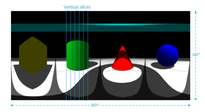
The environment map is composed of multiple slices rendered by the rotating camera
For stereoscopic panorama we will need two viewpoints: one for each eye. Their positions should be slightly offset from the center of rotation. This offset is the Interpupillary distance (IPD). By rotating the two cameras and rendering slices sequentially, we should obtain the two stereoscopic panorama images corresponding to both eyes.
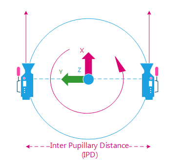
Camera rotates around the view position starting looking at +X
The camera Field of View should be set accordingly to our slice width. By doing this, we make sure that the slices will perfecly fit together during the final assembling.
fov = 2pi / slices_count
Example: we would like an environment map of width 2048 pixels. We decide to divide it in 512 slices of 4 pixels. The horizontal fov will be 2pi / 512. The angle of rotation will be the same.
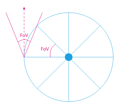
The Field of View is the same angle as the rotation angle
The Zenith and Nadir Issue
The cylindrical panorama works well for the central part of the view. Unfortunately, the view gets more and more distorded as we move towards the poles (don’t look at it with a VR headset: sickness ahead. Really!).
To reduce this distortion effect, one solution is to compute a spherical panorama and decrease the distance between the two cameras as we move toward the poles until eyes are totally merged. The vertical slices will have to be split in several rendering views near the poles.
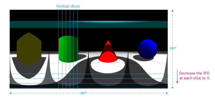
Decrease the IPD toward the poles to “merge” the two views
Drawbacks of the Method
The stereoscopic panorama work pretty well but it also has some drawbacks.
The first one is that the user can’t navigate in the scene (obviously). Using a VR headset, it means that no translation will be taken into account.
The second issue is that the user can only rotate his head horizontally. The up vector should stay the same. Turning the head around X or Y axis will have no effect on the background images.
How to Do It with HOOPS Luminate?
Using HOOPS Luminate, we will have to render each face of the spherical panorama. First we will create a new RED::IViewpointRenderList that will be used to draw the scene. Then for each face, we will have to:
- Setup the
RED::IViewpoint- Render the scene
- Get the generated render image
- Copy the render image to the final environment map
This will have to be done two times: one time for the left eye and one time for the right eye. The purpose of the tutorial being only an example and due to the possibly long rendering time, the sample code only calculates one eye. A global variable allows to change from left to right.
For clarity’s sake, all the data needed to setup the spherical rendering are pre-computed at the initialization stage:
- Render images sizes
- Camera angles
- Camera field of views
- IPD.
In this tutorial, we choose to divide the horizontal into 512 strips of 4 pixels for an environment map of size 2048*1024 pixels. The horizontal FOV is then 2pi / 512.
The vertical is divided like this:
| Strips Count | Strip Height | Vertical FOV | IPD |
|---|---|---|---|
| 1 strip | 64px | pi / 16 | 0 |
| 48 strips | 48 strips * 4px = 192px | 3 * pi / 16 / 48 strips | 0 to max |
| 2 strips | 2 strips * 256px = 512px | 2 strips * pi / 4 | max |
| 48 strips | 48 strips * 4px = 192px | 3 * pi / 16 / 48 strips | max to 0 |
| 1 strip | 64px | pi / 16 | 0 |
| Total | |||
| 100 strips | 1024px | pi | 0 to max to 0 |
Note
Feel free to increase these values to improve your panorama quality. As usual, it’s all a matter of quality vs. rendering speed.
Render in a New Offscreen VRL
First: create and setup a new RED::IViewpointRenderList:
// New VRL:
RC_TEST( iwindow->CreateVRL( g_cube_vrl, g_strip_size_w, g_strip_size_h[0], RED::FMT_RGBA, true, iresmgr->GetState() ) );
RED::IViewpointRenderList* ivrl = g_cube_vrl->As< RED::IViewpointRenderList >();

RC_TEST( ivrl->InsertViewpoint( camera, iresmgr->GetState() ) );
RC_TEST( ivrl->SetClearColor( RED::Color::BLACK, iresmgr->GetState() ) );
RC_TEST( ivrl->SetSoftAntiAlias( 4, iresmgr->GetState() ) );
Setup the Viewpoint
Before rendering each face of the panorama, the viewpoint must be set correctly starting with the camera axes:
// Change the camera axes:
RED::Matrix rot_w, rot;
// Rotation around the Z axis.
RC_TEST( rot_w.RotationAngleMatrix( RED::Vector3::ZERO, 0.f, 0.f, (float)g_camera_angle_w[ g_current_face_w ] ) );
// Rotation around the Y axis.
RC_TEST( rot.RotationAngleMatrix( RED::Vector3::ZERO, 0.f, (float)g_camera_angle_h[ g_current_face_h ], 0.f ) );
// Final rotation around the Z axis then Y axis.
rot = rot_w * rot;

// Rotate the eye position.
RED::Vector3 eye = rot_w.Rotate( RED::Vector3( 0.0, g_camera_ipd[ g_current_face_h ] * ( g_left_eye ? 0.5 : -0.5 ), 0.0 ) );
RED::Vector3 sight( rot.RotateNormalize(  RED::Vector3::XAXIS ) );
RED::Vector3 top  ( rot.RotateNormalize(  RED::Vector3::ZAXIS ) );
RED::Vector3 right( rot.RotateNormalize( -RED::Vector3::YAXIS ) );

RC_TEST( ivp->SetViewingAxis( sight, top, right, iresmgr->GetState() ) );
RC_TEST( ivp->SetEye( g_camera_pos + eye, iresmgr->GetState() ) );
The camera frustum needs to be set accordingly to the desired field of view:
// Change the camera frustum:
double tanfov_w = tan( g_camera_fov_w * 0.5 );
double tanfov_h = tan( g_camera_fov_h[ g_current_face_h ] * 0.5 );

RED::Matrix projmtx;
RC_TEST( projmtx.PerspectiveViewmappingMatrix( -tanfov_w * g_near, tanfov_w * g_near, -tanfov_h * g_near, tanfov_h * g_near, g_near, g_far ) );
RC_TEST( ivp->SetFrustumCustom( projmtx, iresmgr->GetState() ) );
The VRL has to be resized to fit the panorama strip width and height:
// Change the vrl size:
RED::IViewpointRenderList* ivrl = g_cube_vrl->As< RED::IViewpointRenderList >();
RC_TEST( ivrl->SetSize( g_strip_size_w, g_strip_size_h[ g_current_face_h ], iresmgr->GetState() ) );
Render the Scene
Well, nothing more to say that: RED::IWindow::FrameTracing.
Get the Rendered Strip and Fill the Environment Map
The render image can be retrieved from the VRL using RED::IViewpointRenderList::GetRenderImage. The result pixels are copied to the final environment map:
// Get the source calculated render image:
RED::IViewpointRenderList* ivrl = g_cube_vrl->As< RED::IViewpointRenderList >();
RED::Object* renderimg = ivrl->GetRenderImage();
RED::IImage2D* irenderimg = renderimg->As< RED::IImage2D >();
RC_TEST( irenderimg->GetPixels() );
unsigned char* pixsrc = irenderimg->GetLocalPixels();

// Get the destination environment map:
RED::IImage2D* ienvmap = g_env_map->As< RED::IImage2D >();
unsigned char* pixdest = ienvmap->GetLocalPixels();

// Copy the strip to the envmap:
int xdest, ydest, idxsrc, idxdest;
for( int j = 0; j < g_strip_size_h[ g_current_face_h ]; ++j )
{
  for( int i = 0; i < g_strip_size_w; ++i )
  {
    xdest = g_current_face_w * g_strip_size_w + g_strip_size_w - 1 - i; // envmap visually inverted.
    ydest = g_strip_size_h_cumul[ g_current_face_h ] + j;
    idxsrc = ( i + j * g_strip_size_w ) * 4;
    idxdest = ( xdest + ydest * g_env_map_width ) * 4;
    memcpy( pixdest + idxdest, pixsrc + idxsrc, 4 );
  }
}
After rendering each face of the spherical panorama, the environment map is complete. Just save it using the RED::ImageTools::Save function and we are done!
Visualizing the Result
The generated environment maps can be seen by setting them to the background of the VRL.
// Set the pixels to the cube image:
RED::IImageCube* icube = g_cube_image->As< RED::IImageCube >();
RC_TEST( icube->CreateEnvironmentMap( RED::FMT_RGB, RED::ENV_SPHERICAL, 1024,
                                      ienvmap->GetLocalPixels(), ienvmap->GetLocalWidth(), ienvmap->GetLocalHeight(), RED::FMT_RGBA,
                                      RED::WM_CLAMP_TO_BORDER, RED::WM_CLAMP_TO_BORDER,
                                      RED::Color::BLACK,
                                      RED::Matrix::IDENTITY, RED::Matrix::IDENTITY,
                                      iresmgr->GetState() ) );
For Virtual Reality systems (like in the Oculus Rift tutorial), a VRL should be set for each eye. The only thing to do is to apply the environment map generated for each eye to the corresponding VRL background.
Note
HOOPS Luminate contains a project named “OculusPanoramaViewer” and its associated application. It allows to load and display stereoscopic backgrounds in the Oculus Rift device.
References
This tutorial is mainly inspired by the work of Paul Bourke available here: http://paulbourke.net/stereographics/stereopanoramic/