Document Architecture
We have kept the existing document / view class architecture initially provided by the ODA team in the ExRender_Classes group:
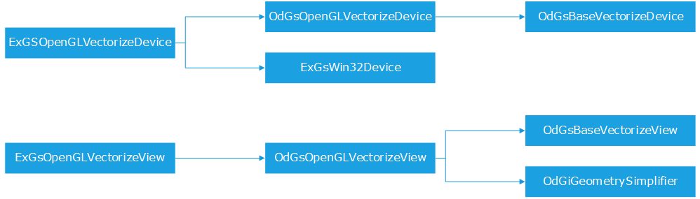
The device / view class architecture
One instance of device is created for each document that is opened. One to many view instances are created for each created device.
Initializing HOOPS Luminate
HOOPS Luminate is initialized during the first update of the first device that has been created. See the ExGsOpenGLVectorizeDevice::InitializeRedsdkCluster method. This method gathers all the necessary elements to bootstrap HOOPS Luminate, as illustrated here: Assembling a Minimal HOOPS Luminate Application.
REDOdaDevice Rendering Workflow
We’re in a multiple view per document architecture. We start an updating process for each view, before jumping into the Teigha update process that will call us back in the vectorization API calls. Then, we do some cleanup and close our transaction before we can proceed with the rendering by HOOPS Luminate.
void ExGsOpenGLVectorizeDevice::update (OdGsDCRect *rect)
{
    // HOOPS Luminate cluster setup and update:
    // --------------------------------

    RC_TEST( InitializeRedsdkCluster() )
    RC_TEST( UpdateRedsdkWindow() )

    RED::IResourceManager *iresmgr = GetIResMgr();
    RED::IWindow *iwindow = GetIWindow();
    RC_CHECK( iresmgr )
    RC_CHECK( iwindow )


    // Start the transaction for each view:
    // ------------------------------------

    int i,nb_views;

    nb_views = numViews();

    iresmgr->BeginState();

    for(i=(nb_views-1);i>=0;i--)
    {
        OdGsView *view = viewAt(i);
        if(view)
        {
            ExGsOpenGLVectorizeView *odview = static_cast<ExGsOpenGLVectorizeView *>(view);
            if(odview)
                RC_TEST( odview->RedsdkTransactionStart() )
        }
    }


    // Connecting the Oda rendering pipeline:
    // --------------------------------------

    OdGsOpenGLVectorizeDevice::update(rect);


    // Setup the background color / depth:
    // -----------------------------------
    //  o Each view will draw a valid z value for the region in which it has
    //    the right to write fragments

    int count;
    RED::Object *vrl;

    RC_TEST( iwindow->GetVRLCount(count) )

    if( count == 1 )     RC_TEST( iwindow->GetDefaultVRL( vrl ) )
    else if( count > 1 ) RC_TEST( iwindow->GetVRL( vrl, 1 ) )
    else                 RC_TEST( RED_FAIL )

    RC_CHECK( vrl )

    RED::IViewpointRenderList *ivrl = (RED::IViewpointRenderList *)vrl->As<RED::IViewpointRenderList>();
    RC_CHECK( ivrl )

    ODCOLORREF bckgnd(m_Background);
    RED::Color backcolor( (float)(ODGETRED(bckgnd)) /255.0f,
                            (float)(ODGETGREEN(bckgnd)) / 255.0f,
                            (float)(ODGETBLUE(bckgnd)) / 255.0f,
                            1.0f );

    RC_TEST( ivrl->SetClearColor( backcolor, iresmgr->GetState() ) );
    RC_TEST( ivrl->SetClearDepth( ( IsSoftware() == true ) ? 1.0f : 0.0f, iresmgr->GetState() ) );


    // Stopping the transaction for each view:
    // ---------------------------------------

    for( i = nb_views - 1; i >= 0; i-- )
    {
        OdGsView *view = viewAt(i);
        if( view )
        {
            ExGsOpenGLVectorizeView *odview = static_cast<ExGsOpenGLVectorizeView *>(view);
            if( odview )
                RC_TEST( odview->RedsdkTransactionStop() )
        }
    }

    RC_TEST( _odbatch.Synchronize( this ) );


    // Do some cleanup in the list of cameras:
    // ---------------------------------------
    //  o Views objects are not destroyed for views that are visually deleted.
    //    Therefore, we are not informed of the removal of a view by other means
    //    of parsing the list of cameras we still have and to compare it with
    //    the list of views that we receive.

    int j;
    RED::Object *camera;

    RC_TEST( iwindow->GetViewpointsCount(count) )

    for(i=0;i<count;i++)
    {
        RC_TEST( iwindow->GetViewpoint(camera,i) )

        for(j=0;j<nb_views;j++)
        {
        OdGsView *view = viewAt(j);
        if(view)
        {
            ExGsOpenGLVectorizeView *odview = static_cast<ExGsOpenGLVectorizeView *>(view);
            if(odview)
            {
                if( camera == odview->GetViewpoint() ||
                    camera == odview->GetViewpointMask() )
                {
                    break;
                }
            }
        }
        }
        if(j == nb_views)
        {
            RC_TEST( iwindow->RemoveViewpoint(camera,iresmgr->GetState()) )
            RC_TEST( iwindow->GetViewpointsCount(count) )
            i--;
        }
    }


    // Remove cameras for clipped views:
    // ---------------------------------
    //  o Update for these views is entirely skipped. In this case, we catch the
    //    modification at the device level.

    for(i=(nb_views-1);i>=0;i--)
    {
        OdGsView *view = viewAt(i);
        if(view)
        {
            ExGsOpenGLVectorizeView *odview = static_cast<ExGsOpenGLVectorizeView *>(view);
            if(odview)
            {
                if(odview->isViewportOnScreen() == false)
                {
                    RC_TEST( iwindow->RemoveViewpoint(odview->GetViewpoint(),iresmgr->GetState()) )
                    RC_TEST( iwindow->RemoveViewpoint(odview->GetViewpointMask(),iresmgr->GetState()) )
                }
            }
        }
    }


    // Software rendering options setup:
    // ---------------------------------

    if( IsSoftware() == true )
    {
        RED::IOptions* iwinopt = GetWindow()->As< RED::IOptions >();
        RC_TEST( iwinopt->SetOptionValue( RED::OPTIONS_RAY_PRIMARY, true, iresmgr->GetState() ) );
        RC_TEST( iwinopt->SetOptionValue( RED::OPTIONS_RAY_TRANSPARENCY, 10, iresmgr->GetState() ) );

        // @note Tech Soft 3D. Here temporarily for debugging purposes ;-)
        //RC_TEST( iwinopt->SetOptionValue( RED::OPTIONS_RAY_MAX_THREADS, 1, iresmgr->GetState() ) );
    }

    RC_TEST( iresmgr->EndState() )


    // HOOPS Luminate rendering:
    // -----------------

    if( IsSoftware() == true )
    {
        bool complete = false;
        while( complete == false )
        {
            RC_TEST( iwindow->FrameTracing( complete, RED::FTF_BY_SURFACE_LEVEL_0, 2000.0f ) );
        }
    }
    else
    {
        RC_TEST( iwindow->FrameDrawing() );
    }

    //DumpRedFile( "c:\\drawing.red" );
}
HOOPS Luminate uses a retained mode API: all changes that have to occur for a frame are done first, then the rendering occurs for the entire window in a single call. This is why we are using a cleanup step right after the startup of the transaction and an update step before we close it: The cleanup step handles transient objects that are created and destroyed in the same update sequence. The update step synchronizes all rendering parameters before the effective draw has to occur.
The Scene is in the Camera
This is something that can be a surprise to new HOOPS Luminate users. Instead of managing one scene and cameras that are nodes inside that scene, HOOPS Luminate manages cameras that are directly linked to the windows that see them and all scene graphs to visualize are attached to the cameras that have to see them.
Practically, a camera is the root of a scene graph. HOOPS Luminate is using a standard Direct Acyclic Graph architecture (see HOOPS Luminate Scene Graph Overview) and the user attaches the root of a scene graph to display as a child of the camera root object. The flexibility of this model is great as it lets any camera visualize any part of any scene graph. Practically, scenes may be composed of many cameras - and this is the case in the device for DWGs that have multiple views. Each camera is linked with all the object or object graph it has to see. The rendering of all these cameras is performed by the window that is able to manage complete lists of cameras (see Viewpoint Render Lists).
Managing Multiple Views
Each view is associated to several HOOPS Luminate cameras: we have one master camera for each view that contains the geometry that has to be rendered. In addition to this we have masking cameras that are used to relimit the view’s rendering area.
Practically, if the call to ExGsOpenGLVectorizeView::SetupMaskingCamera is removed AND if the call to RED::IViewpointRenderList::SetClearDepth uses 1.0f as depth clearance, masking cameras can be disabled, as illustrated by the image below:
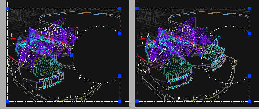
Masking cameras enabled on the left image, disabled on the right image.
Each view renders geometry in its master camera using a regular z-buffer depth filtering. Each masking cameras adds overlapping geometries that render at a depth equals to 1.0f. Consequently, if a primitive is drawn outside of the masking polygon area, then it won’t be displayed because the z-buffer will have been cleared at 0.0f.
Then, if we have to manage the rendering of multiple views, each list of cameras used by each view is added to the list of cameras that are rendered by the window. This way, we can achieve a very flexible scene composition that fits the requirements of the .DWG file format architecture.
Defining Viewpoints
This a tricky part in the device source code. The definition of the camera seems to avoid all existing standard projection models. Therefore to set it properly we have done a copy of the existing OpenGL device viewport code and directly set as a custom projection model inside HOOPS Luminate. The RED::IViewpoint::SetFrustumCustom method lets us do this.
The RedOdaDevice uses the concept of “floating origin” to handle accurately drawings that are at very large or very small scale coordinates. This is implemented by the insertion of a OdGiXformPtr in the vectorization pipeline to offset all translated data back to the origin. This results in a greater display precision. Implementation can be found in the ExGsOpenGLVectorizeView::beginViewVectorization method.

