Mesh Shapes
The mesh shape is the only shape in HOOPS Luminate that displays triangles. As a reminder, in fact, there’s only one shape for each category of graphic primitive to display in HOOPS Luminate (Mesh Shapes for triangles, Line Shapes for lines, Point Shapes for points, Text Shapes for texts).
The mesh shape is created using the RED::Factory and the CID_REDMeshShape, as all other shapes: See Creating and Destroying Shapes for details. It implements the given set of interfaces:
| Interface | Description |
|---|---|
RED::IMeshShape |
Mesh management API. |
RED::IShape |
Global shape API. Controls shape tree navigation and shape attributes. |
RED::IUserData |
User data API to store application custom data associated to a shape. |
RED::IChunkSaver |
Shape serialization interface. |
RED::IReferenceSolving |
Shape serialization interface. |
The RED::IMeshShape, which is the purpose of this paragraph, contains several services:
Geometry Defintion APIs: these methods are used to define the contents of the mesh shape to be displayed.Edge Construction APIs: Line shapes can be constructed from meshes in various manners.Topological Services: simple operations, tangents construction services, or texturing services are also present on the shape.Simple Primitive APIs: A set of simple primitives can be created here: torus, sphere, etc…
Geometry Definition APIs
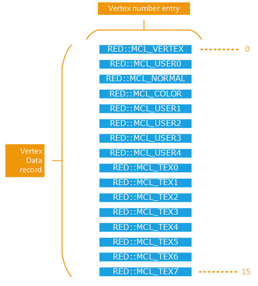
First of all, HOOPS Luminate geometrical primitives are all index based. This means that all geometrical attributes of a mesh are stored per vertex, as illustrated below:

A mesh vertex data record
A given mesh stores up to 16 channels of information for each of its vertices. Each data channel of a vertex is identified by an entry in the RED::MESH_CHANNEL enumeration. Vertices are accessed by their numbers:

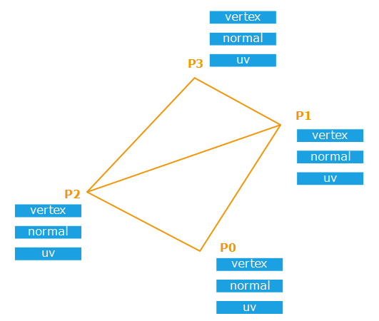
Indexed based vertex access for the rendering
Here, to render the two triangles shown in the illustration, we’ll render vertices 0, 1, 2 and then 1, 3, 2. Therefore, we’ll access geometry channels stored for the 4 vertices, and reuse data records for vertices 1 and 2 that are used by the two triangles.
Then, the RED::IMeshShape API starts by loading geometrical data arrays for all vertices at a time: RED::IMeshShape::SetArray is used to upload a given RED::MESH_CHANNEL data array for all the vertices of the mesh:

The memory layout of a mesh shape
In the example above, we have three data channels per vertex: RED::MCL_VERTEX, RED::MCL_COLOR and RED::MCL_TEX0. Each data channel has a specific data format for each vertex:
RED::MCL_VERTEX: 3 coordinates xyz, stored inRED::MFT_FLOATprecision, hence the total array is 48 bytes for the 4 points mesh.RED::MCL_COLOR: 4 values rgba, stored inRED::MFT_UBYTEprecision, for a total of 4 x 4 = 16 bytes for the mesh.RED::MCL_TEX0: 2 uv values, stored again inRED::MFT_FLOATprecision, for a total of 4 x 2 x 4 = 32 bytes for the mesh.
So we see here that the data storage model of a mesh is very flexible and that many data with various layouts can be stored as vertex attributes for a mesh. Then, as a consequence, each array specified using RED::IMeshShape::SetArray must use the same number of vertices: this is the total number of vertices in the mesh.
Arrays in a RED::IMeshShape are defined using the generic RED::MESH_CHANNEL enumeration. However, some arrays have usual meanings, and are used that way throughout the engine:
RED::MCL_VERTEXis intended to store positions of points in the defined mesh. This is leveraged by both GPU and CPU ray-tracers of HOOPS Luminate, so this is an usage constraint.RED::MCL_NORMALis usually intended to store vertex normals of mesh points.RED::MCL_COLORusually stores vertex colors.- Texture coordinates are by convention often stored using
RED::MCL_TEX0-RED::MCL_TEX7.- Tangent space vectors are often stored in
RED::MCL_USER0.
Then, triangles are specified, that define the mesh surfaces, using RED::IMeshShape::AddTriangles. Please note that triangle strips and triangle fans can be submitted to a mesh, but these are internally turned into triangles. Triangle strips and fans were mostly used in the past to speed-up display performances, but are no longer needed with the way HOOPS Luminate render data.
The following example below illustrates the creation of a simple planar mesh:
Setup a Mesh Geometry Channels
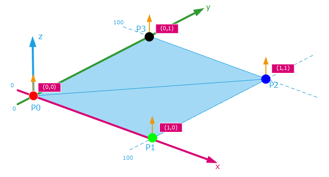
Here, we define a simple plane as shown below:

And the code sequence to realize it is:
// Creating our mesh shape:
RED::Object* mesh = RED::Factory::CreateInstance( CID_REDMeshShape );
if( !mesh )
    RC_TEST( RED_ALLOC_FAILURE );

RED::IMeshShape* imesh = mesh->As< RED::IMeshShape >();

// We want to create a plane in this example: 4 vertices, with: positions, normals, vertex colors and texture coordinates:
float position[12] = { 0.0f,   0.0f,   0.0f,
                       100.0f, 0.0f,   0.0f,
                       100.0f, 100.0f, 0.0f,
                       0.0f,   100.0f, 0.0f };

float normal[12] = { 0.0f, 0.0f, 1.0f,
                     0.0f, 0.0f, 1.0f,
                     0.0f, 0.0f, 1.0f,
                     0.0f, 0.0f, 1.0f };

unsigned char color[16] = { 255, 0,   0,   255,
                            0,   255, 0,   255,
                            0,   0,   255, 255,
                            0,   0,   0,   255 };

float uv[8] = { 0.0f, 0.0f,
                1.0f, 0.0f,
                1.0f, 1.0f,
                0.0f, 1.0f };

RC_TEST( imesh->SetArray( RED::MCL_VERTEX, position, 4, 3, RED::MFT_FLOAT, iresmgr->GetState() ) );
RC_TEST( imesh->SetArray( RED::MCL_NORMAL, normal, 4, 3, RED::MFT_FLOAT, iresmgr->GetState() ) );
RC_TEST( imesh->SetArray( RED::MCL_COLOR, color, 4, 4, RED::MFT_UBYTE, iresmgr->GetState() ) );
RC_TEST( imesh->SetArray( RED::MCL_TEX0, uv, 4, 2, RED::MFT_FLOAT, iresmgr->GetState() ) );

// Then we need to define our mesh triangles:
int index[6] = { 0, 1, 2,
                 0, 2, 3 };

RC_TEST( imesh->AddTriangles( index, 2, iresmgr->GetState() ) );
Sharing Geometry Channels
This a very important feature in HOOPS Luminate: All geometrical primitives (points, lines, meshes) can share their source data with an external source. This means that a given vertex array can be shared by several shapes or by one shape and an external provider (such as a modelling package like ACIS or PARASOLID).
Data arrays in a mesh can be shared. Instead of calling RED::IMeshShape::SetArray, use RED::IMeshShape::SetSharedArray. Similarly, to share mesh indices, call RED::IMeshShape::SetSharedTriangles.
Using shared arrays overflow the HOOPS Luminate transaction system. HOOPS Luminate transactions are meant to allow data modification in parallel to the draw. Using shared arrays, this is no longer possible, as the mesh has only one data source array available. Therefore, modifying shared data should be done with caution by the application, and should not occur on an auxiliary thread while a rendering occurs.
Edge Construction APIs
The RED::IMeshShape offers several edge construction methods. This can be used to extract all edges in a given mesh. These methods do create a new CID_REDLineShape object, that implements the RED::ILineShape interface:
RED::IMeshShape::BuildEdges: Constructs a shape simply set with all edges of a mesh, without any redundancy (an edge shared by two triangles appear once in the resulting shape).RED::IMeshShape::BuildBorderEdges: Constructs only border edges of a mesh. Border edges are only used by one triangle in the mesh.RED::IMeshShape::BuildContourEdges: Constructs all edges with contouring extraction information. This can be used to render real-time silhouettes.
Please refer to each method documentation for details on these edge shape construction methods.
Topological Services
The RED::IMeshShape also offers a few services to manipulate the mesh it stores:
- A collapse method:
RED::IMeshShape::Collapse, used to remove duplicate vertices in a mesh, and to reform the mesh after the operation.- Normals of a mesh can be recalculated using
RED::IMeshShape::Shade, orRED::IMeshShape::ShadeTJunctionto redefine normals for meshes that have cracks in their topology.- Triangle winding can be reversed. The visible face of a triangle (P0,P1,P2) is pointed to by the result of cross( P0P1, P0P2 ), and this method reversed the result of the cross operation by switching P1 and P2 for each triangle in the mesh.
- Texturing services:
RED::IMeshShape::BuildTextureCoordinatescan be used to (re)define UVs associated to the geometry.
Simple Primitives APIs
For some reasons, even after dozen of years in 3D graphics, we still need simple primitives sometimes. The ‘’RED::IMeshShape’’’ offers a few basic geometry creation services:
RED::IMeshShape::QuadRED::IMeshShape::BoxRED::IMeshShape::CylinderRED::IMeshShape::ConeRED::IMeshShape::TorusRED::IMeshShape::Sphere

