Setup Geometries
The purpose of this page is to have a general discussion on the geometrical setup of a scene. We have already discussed the fact that lights should have their own support geometries so we won’t discuss this any further here. However, for other geometries, there are a few tricks to be aware of to create stunning images.
Incomplete Scenes Will Give Incomplete Results
The first important point in the scenery is to make it real. There are countless models that are incomplete and for which, unfortunately, rendering algorithm will fail to produce a realistic feeling. Let’s look at the very old kitchen model below as it appears in the Autodesk 3dsMax (c) viewport:
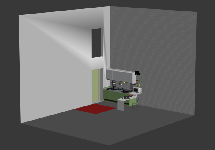
An old kitchen model in an open environment.
The rendering is…let’s say it’s not really bad, but it’s not really good either:
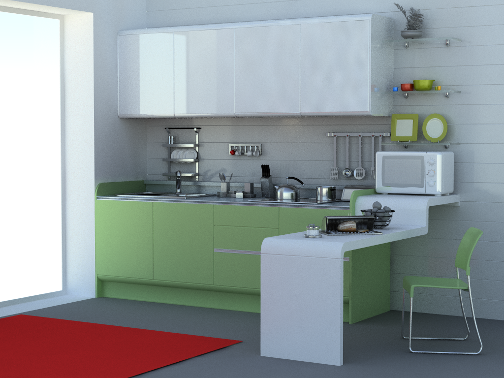
The rendering of the open kitchen scene (draft quality).
The problem with this model is that we don’t have any feeling of the light. Consequently, the scene is more or less “floating in the air”. From what we see, we should have a strong feeling that the light gets in through the window. All this is due to the fact that the environment surrounding our model is incorrect. We’re in an open space with two walls, but no ceiling and no back walls. This don’t happen in real life. We should have a closed room.
So if we change the model and close it with a ceiling and two back walls, we get a completely different feeling of the scene, which is rendered using the same lighting conditions:
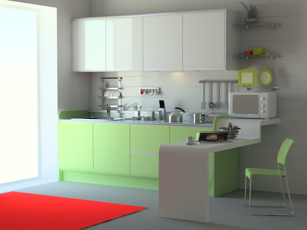
The same kitchen scene after having closed the environment (draft quality).
Here we get to the point of that paragraph: an incomplete scene will not behave in a realistic manner. This is an important question to ask yourself: how is the environment in which my model is being displayed? Is it correct? For instance, this is very important for any object design applications. It’s not possible to make a good image out of an object put over an infinite plane. This don’t exist in real life. At least we must have a realistic HDR environment to capture the complexity of the lighting that surrounds the object as it would look like in real life.
Please Add Polygons to your Geometries!
Scary geometries. Were OK 10 years ago!
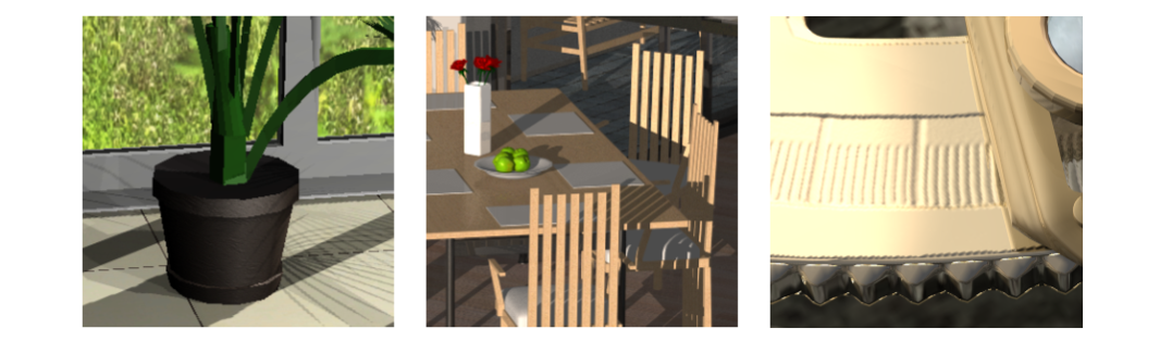
This was already discussed a bit in the book heading page. Low quality geometries can’t do the job. Period. Please replace them! HOOPS Luminate can render scenes with millions of triangles; so don’t hesitate to spend a big polygon budget in auxiliary geometries. A nice indoor green plant may consume 500.000 triangles.
Eye Catching Geometric Details
This small section item is about how geometries can “catch” the light. Real geometries are never so harsh as computer graphics geometries are. But small geometric imperfections are somehow needed for a realistic look. In the example below, the sofa has a complex geometry that make it look comfortable:
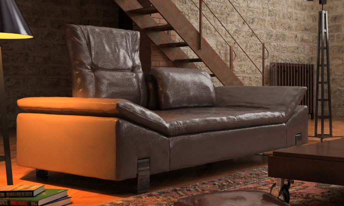
A nice looking sofa
This single piece of geometry has around 100.000 triangles in it. Without getting up to this level of detail, the addition of chamfers or fillets to break hard edges may help a lot “catching the light”:
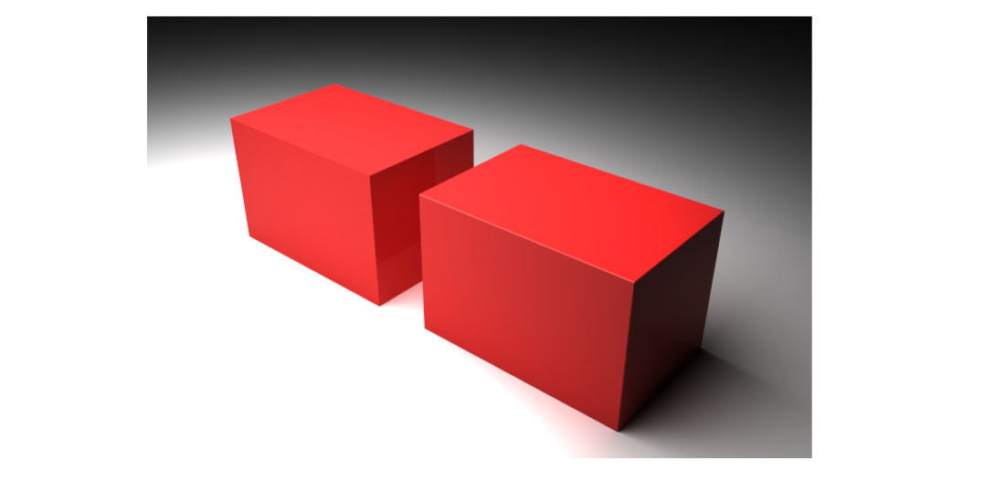
Effect of adding very small fillets or chamfers to geometries increase their realism in catching more light.
The right cube has a simple chamfer. It’s small, but large enough so that we can see the reflection of the light shape in it. Similarly, the chamfer helps getting the feeling that the cube is lying on the floor.
Using Displacement Mapping
Displacement mapping is a nice feature to generate extra detailed geometry that replaces modelling. Using displacement mapping may have a high performance cost (up to x3) on the rendering time, but without having to do the modelling or to pay any extra price in terms of memory storage.
One important point on displacement mapping is that bump maps generally don’t do good displacement maps. A bump map emphasizes geometry details, but these details are all fake details as the geometry itself is not modified (which is obvious on silhouette edges). A displacement map creates real geometric details, so the effect is much more visible than the one generated by a bump map. Therefore a displacement map should discard all the high frequency signal that can be found in a bump map. The image below illustrates these differences:
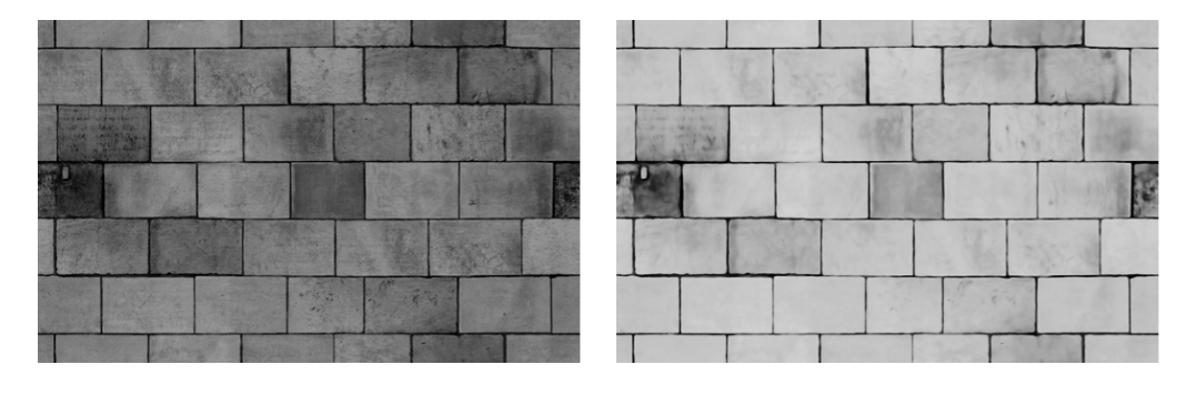
Bump map on the left vs. displacement map on the right.
The displacement map has lost a lot of small height variations compared to the map to be used for the bump. Using the bump map as a displacement map produces a perturbated geometry as shown below, compared to the use of a filtered displacement map:
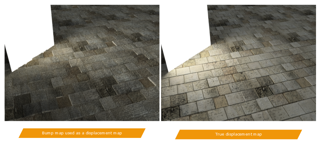
Bump rendering vs. displacement rendering.
Adding Extra Geometries to a Scene
This has been already covered in the book’s top page, so we just recall here the importance of having extra setup geometries in a scene to make the whole scenery look realistic; If we look at the example below:
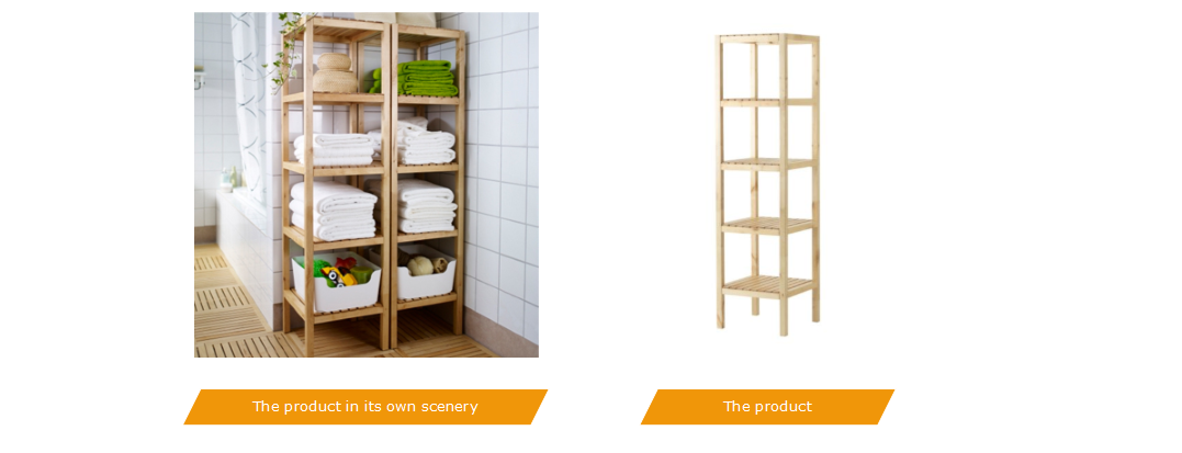
The product in its own scene to show it “in context”, and the real isolated product.
We see that the product is introduced in a complete context, before being isolated for details. It does not look as appealing when shown alone. In this specific example, the scenery does really matter.

